World Journal of Environmental Biosciences
All Rights Reserved WJES © 2014
Available Online at:
www.environmentaljournals.org
Volume5, Issue 3: 15-20
ISSN 2277- 8047
An Efficient Method to Prevent Progressive Collapse of Steel and RC Buildings
Ramezan Ali Izadifard
*1
Civil Engineering Department, Imam Khomeini International University, IRAN.
ABSTRACT
Progressive collapse is a catastrophic structural phenomenon that can occur because of natural hazards or human-made like explosive or impulsive loads. In this event, a single local failure may cause a significant deformation which then may lead to the collapse of a structure. In this paper, progressive collapse potential of several five, eight and ten story buildings of steel and reinforced concrete structures which have been designed according to AISC-LRFD and ACI following the removal of an exterior column is evaluated. In addition, an efficient and simply method -based on the beam’s depth to length ratio (D/L)- proposed to prevent progressive collapse of structures. It is shown we can avoid from progressive collapse of steel and RC structures if the depth of the beams around the removed column choose more than L/15 and L/12 respectively.
Keywords: Progressive Collapse, Depth to length ratio, Steel Structures, RC Buildings.
Corresponding author: Ramezan Ali Izadifarda
e-mail[email protected]
1. INTRODUCTION
Progressive collapse is defined as the spread of an initial local failure from element to element, eventually resulting in the collapse of an entire structure or a disproportionately large part of it (ASCE/SEI, 2005). Recent terror attacks demonstrated that most casualties are due to building collapse rather than the initial explosion or impact. That is, this kind of structural failure increases the likelihood of mass casualties. Progressive collapse has been an important issue in structural failure since a partial collapse of the Ronan Point apartment building in 1968. The attack on the Murrah Federal building in 1995 and World Trade Center on September 11, 2001, started a second wave of attention on structural failure and better understanding of progressive collapse. Several expert committees had investigated to rethink and improve their standards pertaining to progressive collapse design procedures. These include, for instance, the United States Department of Defense (DOD, 2005), the United States General Services Administration (GSA, 2003), or the Euro Codes (2006). ASCE Standard 7-05 (2005) defines the alternate load path method (allowing for redistribution of load in the event of the loss of a key member) as one of three approaches1 to attain progressive collapse resistance. In this
method, the designer localizes response by designing the structure to carry loads by means of an alternate path in the event of the loss of a primary load-bearing component. It needs to reliable information on the load transfer mechanisms in beams, slabs and columns when a critical column is removed
11) Indirect Method, 2) Specific Local Resistance Method, and
3) Alternate Load Path Method. The latter two methods are referred to collectively as direct methods.
(Qian et al., 2014; Mirzaeia and Sasani, 2013; Alashker et al., 2010; Dat and Tan, 2014). Yi et al. (2014) have studied on elastic behavior, yield-line mechanisms and compressive and tensile membrane actions in a few slab-column structures during the collapse tests.
Some studies (Habibi et al., 2012; Gouverneur et al., 2013) have indicated that integrity reinforcement of slabs may enhance the behavior of steel and RC structures. Few studies have emphasized on membrane action of slabs (Keyvani et al., 2014) and increasing of structural members’ catenary action by GFRP (Qian and Li, 2015) or steel cables (Astaneh-Asl, 2003) to resist against progressive collapse. A feasible proposition would be to consider alternative fall-back parameters such as secondary load carrying mechanisms that can help to reduce the severity of the collapse, should it actually occur (Qian et al., 2014). Author has proposed some methods to prevent progressive collapse by using diagonal steel cables for existing steel structures (Izadifard, 2013), horizontal steel cables for RC buildings (Ghanbari, 2010) and hat trusses seated on top of existing or new steel and RC structures (Badinrad, 2013). Also beam-column connections retrofitting to enhance the survival capacity of the steel framed structures subjected to a blast or impact is proposed by changing the partial-strength shear-resisting joints to the full-strength moment-shear-resisting joints (Liu, 2010; Nikfar, 2013).
between depth and length of perimeter beams is obtained to prevent progressive collapse.
2. CHARACTERISTICS OF BUILDINGS AND MATERIALS
In this paper, few five, eight and ten-story steel and reinforced concrete buildings with special and intermediate moment frames having five bays in each direction are studied. Their span length and height of stories are considered different.
2.1. Steel Structures:
Table 1 shows the different geometrical characteristics of steel structure buildings. The steel used in this study is ASTM-A36 with modulus of elasticity equal to 210 Gpa. The yield and ultimate strength of steel elements in the steel structures are 240 and 330 Mpa respectively. The floor system consists of composite concrete floor slabs. The concrete compressive strength is set equal to 24 Mpa for a standard 28-day old concrete cylinder.
Table 1. Geometrical features of steel structures
Model stories Span Length (cm) Moment Type of Frame
Story Height
(cm)
SA1 5 500 Intermediate 330 SA2 5 500 Special 330 SA3 5 600 Intermediate 330 SA4 5 600 Special 330 SA5 5 700 Intermediate 330 SA6 5 700 Special 330 SA7 8 600 Intermediate 330 SA8 8 600 Special 330 SA9 8 700 Intermediate 330 SA10 8 700 Special 330 SA11 10 600 Intermediate 350 SA12 10 600 Special 350 SA13 10 700 Intermediate 350 SA14 10 700 Special 350
2.2. Reinforced concrete structures
An overview of the different geometrical characteristics of reinforced concrete buildings is given in table 2. The buildings are assumed to be located on a site class B, rock (IBC, 2003). The height of each floor is considered 350 cm. The 28-day old concrete compressive strength of standard cylindrical sample is equal to 24 Mpa. The modulus of elasticity and poisson's ratio of concrete are considered 23400 Mpa and 0.15 respectively. The modulus of elasticity (Ec), the yield tensile stress (fy) and the
ultimate strength (fu) of reinforcing bars are considered 210
GPa, 350MPa and 500 Mpa respectively.
Table 2. Geometrical features of RC structures
Model stories Span Length (cm) Moment Type of Frame
Story Height
(cm)
CA1 5 500 Intermediate 350 CA2 5 500 Special 350 CA3 5 600 Intermediate 350 CA4 5 600 Special 350 CA5 5 700 Intermediate 350 CA6 5 700 Special 350 CA7 8 600 Intermediate 350 CA8 8 600 Special 350 CA9 8 700 Intermediate 350 CA10 8 700 Special 350 CA11 10 600 Intermediate 350 CA12 10 600 Special 350 CA13 10 700 Intermediate 350 CA14 10 700 Special 350
3. PROGRESSIVE COLLAPSE SIMULATION BY FINITE
ELEMENT METHOD
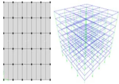
Use of numerical methods in prediction of structural response to blast loading and impact are inevitable. The accuracy of any modeling effort to assess the risk of progressive collapse of a structure depends on how well the material behavior, crack, failure, and contact between different parts of a model are captured. In order to study the response of the building following the removal of the column, a FEM model of the structure needs to be developed. In this study, the three dimensional structural model have been implemented in computer program ABAQUS 6.10(2010). Since the computer program ABAQUS is not able to design structures based on the current design codes, the three dimensional models of the buildings are first developed in E-TABS v.9.1.6 (2005). In the latter modeling, the load combination recommended by the International Building Code IBC-03 (2003) is used and a response spectrum analysis is conducted. The steel structures are designed in compliance with the AISC-LRFD (1999) and the RC structures are designed in compliance with the ACI 318-05 (2005). Fig. 1 shows the plan of a RC building and 3D view of a steel frame that are modeled in E-TABS (2005).
After this stage, models of steel and reinforced concrete frames are developed in ABAQUS software. These models utilize 3D deformable BEAM elements for the steel members. The mesh of BEAM element is the type of B31 which is representative of two-node linear element, and the size of elements (uniform seeds) is considered to be 100 mm. Note that a Ductile Damage model2 is
used to model the behavior of steel under three-dimensional states of stress. In the models, the contact between different parts of the model is considered to be the type of General3. The
equivalent loads of walls and floors are applied to the beams of frames. The progressive collapse of a structure is involved with linear deformation of structural elements. Therefore, non-linear analysis is more preferable to non-linear analysis to investigate the progressive collapse potential of structures. Dynamic explicit finite element analysis is conducted to study the steel frames. Also the gravity acceleration is considered equal to 9810 mm/s2.
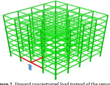
In order to simulate of the column removal, an upward concentrated load is applied under the joint instead of the removed column in ABAQUS software (Fig. 2). This load is equal to axial load that obtained from structural analysis by ETABS software under service loads (dead load and half of live load) in the above mentioned column before elimination. The progressive collapse analysis begins by losing the upward concentrated load suddenly.
Figure 2. Upward concentrated load instead of the removed column
For reinforced concrete structures, three dimensional models of the buildings are developed in ABAQUS 6.10. These models utilize 3D deformable solid sections for the concrete and 3D deformable truss sections for the reinforcing bars. The mesh of solid element is the type of C3D8R which is representative of 8-node linear brick, and the size of elements (uniform seeds) is considered 100 mm. The mesh of truss element is the type of T3D2 which is representative of 2-node linear 3D truss, and the size of reinforcing bar elements are 200 mm. Note that a Brittle Cracking model is used to model the behavior of concrete under three-dimensional states of stress. In these models, the contact between steel bars and concrete is the type of Embedded Region. Fig. 3 shows two stages of the collapse progress of a RCbuildings (CA1 model) from span to span with cracking and destruction of slab and beams following the removal of an exterior column.
2The material damage initiation capability for ductile metals is
intended as a general capability for predicting initiation of damage in metals, including sheet, extrusion, and cast metals as well as other materials
Figure 3. The collapse progress of RC building following the removal of an exterior column
Fig. 4 illustrates the vertical displacement time history of the top of removed column in two buildings for instance. When above mentioned joint moves down, the end of the surrounding beams deforms severely. The ratio of end displacement to length of the beam will be assumed the equivalent rotation of beam’s far support. If this ratio exceeds from 0.04 radian, the progressive collapse will be started. Rapid slope at the curves in fig. 4 implicate on the collapse extension following the column removal.
Figure 4. Vertical displacement at the top joint of removed column
4. USING AN EFFICIENT METHOD TO PREVENT
PROGRESSIVE COLLAPSE
The main aim of this paper is introduce a mechanism to prevent progressive collapse of buildings based on depth increasing of surrounding beams around the removed columns. After sudden column lose, if the equivalent rotation of the surrounding beams be less than 0.01 radian, we can assume the behavior of structure is linear elastic. When rotation exceeds from 0.01, beam damage will be increased gradually so that 0.02 radian, light damage will be emerged in the beams and their supports. At rotation equal 0.04 radian, the collapse will be begun (UFC 2008). To prevent progressive collapse, this research suggests the far support’s rotation of surrounding beam (ƟE) should be
limited to 0.02 and .015 radian for steel and RC structures respectively.
3Allows very simple definitions of contact with very few
Figure 5. The support’s equivalent rotation
Assume: ƟE≤ 0.02 rad → δall≤ 0.02 L (1)
From structural linear elastic analysis, we can obtain the deflection of cantilever beam:
δ = P L3 / 3EI (2)
that, E is the modulus of elasticity and I is moment inertia of the beam. By replacing of Eq.1 at Eq. 2:
Pall≤ 0.06 EI / L2 (3)
Mall = Pall. L ≤ 0.06 EI / L (4)
To consider dynamic phenomenon effect of column removal, it is necessary to imply dynamic increasing factor (DIF) on the static load. Since DIF is about 1.2 to 2 depending on the ratio of structural natural period to loading period, we can assume an approximate amount such as 1.5. So:
M(Dynamic)≤ 0.04 EI / L (5)
In steel structures, the maximum normal stress due to bending moment (Mc/I) should be smaller than yield stress (Fy). If the
strength reduction factor be considered 0.9, we can rewrite the Eq.5:
0.04 EsI / L ≤ [Fy. I / c] / .9 (6)
that c is the half of steel beam’s depth (D). By considering E=200
GPa and Fy=240 MPa;
C ≥ L / 30 . or. D ≥ L / 15 (7)
For RC beams (Fig.6):
Figure 6. Cross section of RC beam and stress distribution
.85 f’cab = ρbdfy → a= αd ; α = ρfy/.85f’c (8)
M= ρfy (1- α/2) bd2 (9)
I=ba3/3 + As(d-a)2Es/Ec→ I=βbd3; β=α3/3+ρ(1-α)2Es/Ec
(10)
.03 EcI /L ≤ M / .9 → d ≥ [37 ρfy(1- α/2)/ βEc] L (11)
d is the effective depth of the beam (distance between center of tensile bars to compressive face of concrete) and it is considered about .9 of beam’s depth (D).
One thousand sample of RC beams with different reinforcement
ratio (ρ =.75% - 2.2%), f’c (20 – 40 MPa) and fy (300 – 400 MPa)
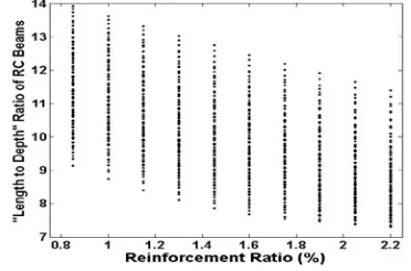
are investigated and the “length to depth” ratio are obtained. An overview of the calculated values of the length to depth ratio is highlighted in fig. 7. By looking at the results reported in fig. 7, it can be seen that the ratio varies from 8 until 14 depending on reinforcement ratio, compressive strength of concrete and yield stress of steel bars. So, this ratio can be suggested 12 for convenient RC beams safety.
Figure 7. Variation of L/D to prevent progressive collapse of RC buildings
Fig.8. shows comparison between vertical displacements at the above of removed column in two cases: 1) when the steel structure has been designed in compliance with what specified in the AISC-LRFD code (normal design=ND), 2) the depth of
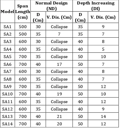
perimeter beams in above mentioned steel structure increases to L/15 (DI). This comparison illustrates if the depth of the perimeter beams increases to L/15, progressive collapse due to column removal will be prevented. All of SA models have been investigated in two above mentioned cases and their results have summarized in table 3. The results in table 3 show the steel structures can be survived after removal of an exterior column by considering D/L ratio more than 1/15.
Figure 8. Comparison between vertical displacements at model SA8 in case of ND (normal design) and the case of
Table 3. Results of steel structures analysis in ND and DI
Model Length Span (cm)
Normal Design
(ND) Depth Increasing (DI) D
(Cm) V. Dis. (Cm) (Cm) V. Dis. (Cm) D
SA1 500 30 Collapse 35 9 SA2 500 35 7 35 7 SA3 600 30 Collapse 40 8 SA4 600 35 Collapse 40 5 SA5 700 35 Collapse 50 10 SA6 700 40 17 50 7 SA7 600 30 Collapse 40 8 SA8 600 35 Collapse 40 7 SA9 700 35 Collapse 50 12 SA10 700 40 19 50 10 SA11 600 35 Collapse 40 12 SA12 600 35 Collapse 40 9 SA13 700 40 21 50 14 SA14 700 40 20 50 12
The same procedure discussed above can be followed for reinforced concrete structures. The comparison between vertical displacements at the above of removed column are summarized in table 4 with respect to normal design of RC structures and depth increasing to L/12. One of these results has been highlighted in Fig. 9 for model CA1. Table 4 and fig. 9 emphasize the progressive collapse of RC buildings due to column removal that can be prevented by increasing the depth of perimeter beams more than L/12.
Figure 9. Comparison between vertical displacements at model CA1 in case of ND and the case of increasing the depth to
L/12 (DI)
Table 4. Results of RC structures analysis in ND and DI Model Span
Length (cm)
Normal Design (ND) Depth Increasing (DI) D (Cm) V. Dis. (Cm) D (Cm) V. Dis. (Cm)
CA1 500 38 Collapse 45 4 CA2 500 38 12 45 4 CA3 600 40 Collapse 50 14 CA4 600 40 Collapse 50 11 CA5 700 50 Collapse 60 14 CA6 700 50 Collapse 60 12 CA7 600 40 Collapse 50 17 CA8 600 40 Collapse 50 16 CA9 700 50 Collapse 60 20
CA10 700 50 Collapse 60 17 CA11 600 40 Collapse 50 21 CA12 600 40 Collapse 50 20 CA13 700 50 Collapse 60 22 CA14 700 50 Collapse 60 22
5. CONCLUSION
Progressive collapse is a catastrophic structural phenomenon that can occur because of a single local failure. Many researches have been done to understand the behavior of structure after sudden column removal. Also some papers have proposed various methods to prevent progressive collapse such as integrity reinforcement of slab, retrofitting of beam to column connections, strengthening of slabs with FRP and using horizontal or orthogonal cables and using hat trusses as an alternate load path method. In this paper, an efficient and simply method -based on the beam’s depth to length ratio (D/L)- proposed to prevent progressive collapse of structures. For this purpose, progressive collapse potential of several five, eight and ten story buildings of steel and reinforced concrete structures which have been designed according to AISC-LRFD and ACI following the removal of an exterior column are evaluated. It is shown we can avoid from progressive collapse of steel and RC structures if the depth of the beams around the removed column choose more than L/15 and L/12 respectively.
ACKNOWLEDGEMENTS
The author is grateful for the granting sabbatical from Imam Khomeini International University and also from National University of Malaysia (UKM) because of its cooperation in this research.
REFERENCES
1. ABAQUS (2010), ABAQUS User’s manual version 6.10, Dassault Systems Simulia Corporation.
2. ACI Committee 318 (2005), Building Code Requirement for Structural Concrete (ACI 318-05) and Commentary (318R-05), American Concrete Institute, Farmington Hills, MI, 430.
3. AISC (1999), Manual of steel construction-LRFD, American Institute of Steel Construction., Chicago, IL. 4. Alashker, Y., El-Tawil, S. and Sadek, F. (2010),
“Progressive Collapse Resistance of Steel-Concrete Composite Floors. J. Struct. Eng., ASCE, 136(10). 5. ASCE/SEI. (2005), Minimum design loads for
buildings and other structures, Structural Engineering Institute, American Society of Civil Engineers, Reston (VA).
6. Astaneh-Asl, A. (2003), “Use of Catenary Cables to Prevent Progressive Collapse of Buildings”, Final Report, department of civil and environmental engineering college of engineering university of California at Berkeley.
8. Dat, P. and Tan, K. (2014), “Experimental Response of Beam-Slab Substructures subjecte to Penultimate-External Column Removal”, J. Struct. Eng., ASCE, 141(7).
9. Department of Defense (DoD) (2005), Unified Facilities Criteria (UFC): Design of Structures to Resist Progressive Collapse, Washington, D.C. 10. EN 1991-1-7 (2006), Eurocode 1-Actions on
structures - Part 1-7: General Actions - Accidental actions, Eurocode.
11. ETABS (2005), Three dimensional static and dynamic finite element analysis and design of structures, analysis reference, version 9.6.0(non-linear, computer and structures), Inc., Berkeley, CA. 12. Ghanbari, F. (2010), “Use of Horizontal Steel Cables to
Prevent Progressive Collapse of RC Structures Subject to Explosion Loads”, M.Sc. Thesis in Structural Eng., (Supervisor: R.A. Izadifard), Imam Khomeini Int.Un.
13. Gouverneur, D., Caspeele, R. and Taerwe, L. (2013), “Effect of Reinforcement Curtailment on Deflections, Strain and Crack Development in RC Slab under Catenary Action”, Magazine of Concrete Research, 65(22), 1336-1347.
14. GSA (2003), Progressive collapse analysis and design guidelines for new federal office buildings and major modernization project, United States General Services Administration Washington D.C.
15. Habibi, F., Redl, E., Egberts, M., Cook, W. and Mitchell, D. (2012), “Assessment of CSA A23.3 Structural Integrity requirements for Two-Way Slabs”, Canadian J. of Civil Eng., , 39(4), 351-361.
16. IBC (2003), International Building Code, International Code Council. Country Club Hills, IL, 17. Izadifard, R.A., Sargazi, O. and Ghanbari, F. (2013),
“Use of High Strength Steel Cables to Prevent Progressive Collapse of Existing Steel Structures”, 10th Int. Con. On Shock & Impact Loads on Structures, 25-26 Nov., Singapore.
18. Keyvani, L., Sasani, M. and Mirzaei, Y. (2014), “Compressive membrane action in Progressive Collapse Resistance of RC Flat Plates”, Engineering Structures, 59, 554-564.
19. Liu, J.L. (2010), “Preventing Progressive Collapse through Strengthening Beam-to-Column Connection, Part 1: Theoretical Analysis”, J. constructional steel research, 66, 229-237.
20. Mirzaeia Y. and Sasani M. (2013), “Progressive Collapse Resistance of Flat Slabs Modeling Post-Punching Behavior”, Computers and Concrete, 12(3), 351-375.
21. Nikfar. M.R. (2013), “Analysis of Progressive Collapse with Some Type of Moment Resistance Connections”, M.Sc. Thesis in Structural Eng., (Supervisor: R.A. Izadifard), Imam Khomeini Int.Un.
22. Qian, K. and Li, B. (2015), “Strengthening of Multibay Reinforced Concrete Flat Slabs to Mitigate Progressive Collapse”, J. Struct. Eng., ASCE, 141(6).
23. Qian, K., Li, B., and Ma, J. (2014), “Load-Carrying Mechanism to Resist Progressive Collapse of RC Buildings”, J. Struct. Eng., ASCE, 141(2).