Abstract—Fluidized bed reactor (FBR) can be an efficient alternative solution in advanced water treatment processes. Fenton oxidation is popular among other advanced oxidation processes. FBR-Fenton process can reduce production of sludge in water treatment and also offers lower hydraulic retention time compared to other biological and chemical processes. This research work is an attempt to develop basic steps to design this FBR. A practical design protocol of the feature for treating phenolic water was developed. Detailed design parameter studies which include different correlations for calculating the required design parameters. The design calculations have been done based on literature and some collective assumptions. From this work it can be summarized that, calculated flow rate for working fluid was found to be 1.4 l /min or more for complete fluidization, where the settling velocity of the particle was found to be 0.0365 m/s and the calculated Reynolds number implied that, the fluidization to be a laminar fluidization.
Index Terms—Fluidized bed, water treatment, design.
I. INTRODUCTION
Fluidized bed reactor is widely applied in many industries for various applications recently. It has been found promising to use fluidized bed reactor for water treatment procedures. When the conventional treatment procedures failed to remove recalcitrant compounds in waste water, advanced oxidation processes came as a foremost choice by the researchers. However, AOPs are yet not without limitations. Studies reveal that an effective contacting device system can increase the potential of advanced oxidation systems. Some authors have used Fluidized bed reactor with conventional treatments procedures, such as, activated carbon [1], [2], anaerobic treatment [2], [3] and also electrochemical
4
limitations likes, increase in toxicity level [5], more power consumption, plugging and clogging [6] and less degradation efficiency [7]. AOP merge with FBR can be more potential in pollutant abatement. One of the advanced technology that can be highlighted as the most efficient for recalcitrant water treatment is Fenton oxidation. Initiatives have been done on using FBR with Fenton procedures, such as photo-Fenton oxidation in fluidized bed reactor [8], heterogeneous Fenton
work was supported in part by the University of Malaya High Impact Research Grant (HIR-MOHE- D000038-16001) from the Ministry of Higher Education Malaysia and University of Malaya.
Farhana Tisa, Abdul Aziz Abdul Raman, and Wan Mohd Ashri Wan Daud are with the Department of Chemical Engineering, University of Malaya, Kuala Lumpur, PO 50603 Malaysia (e-mail: [email protected], [email protected], [email protected]).
oxidation [9], homogeneous fluidized bed Fenton process [10], [11]. Fluidized bed reactor adds some advantages to the Fenton procedures such as, uniform heat and mass transfer, reduction of sludge production, less oxidant usage and more users friendly. Although fluidized bed Fenton have been studied much, few or no significant studies have been done on the studying the design procedures for FBR-Fenton.
Fluidized Bed reactor is a process which is now widely applied in many industrial applications. In recent studies it is evident that, fluidized bed reactors can also be an attractive procedure for treating polluted water. Waste water that is generated from many industries is highly recalcitrant and is threatening to environmental ecology and human lives. Biological and chemical processes have failed to convert the contaminants fully as, biological and chemical processes and degrade up to 60% of the recalcitrant components and in addition they require larger operation area and more chemical processes to reduce the sludge. Advanced treatment technologies that involve highly oxidizing compounds like OH has overcome the limitations of biological and chemical treatment procedures. Through review it can be said Fenton process is more productive when the reaction gets a efficient reaction platform, that is Fluidized bed reactor. Fluidized bed reactors have been used and design for different physical and chemical process for example, catalytic cracking, fluid transportation and drying. Due to increasing importance of treatment of wastewater in FBR critical examinations of the parameters that possesses the design and operation of the treatment procedure have been done on this paper. The methodology section provides the design strategy involving hydrodynamics, thermal and kinetic nature. Essential recommendation towards design calculation has been summarized in the result section. This work will focus on design of the FBR for pollutant treatment.
II. POLLUTANT DEGRADATION IN FLUIDIZED BED REACTORS
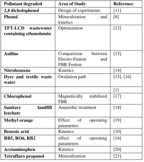
Fluidized bed reactors can be considered as an improvement over the traditional water treatment methods associated with Fenton oxidation for pollutant degradation. Operation of FBR has confirmed many advantages that include high degradation efficiency, lesser reaction time and better catalyst re-circulation. Technical knowledge about design and operation of FBR is not widely available. Also little has been done in the field of designing FBRs. Table I represents studied subjects on FBRs for pollutant degradation. Degradation of pollutant in fluidized bed reactor involves chemical reactions and liquid-solid-gas flow structures.
Basic Design of a Fluidized Bed Reactor for Wastewater
Treatment Using Fenton Oxidation
Farhana Tisa, Abdul Aziz Abdul Raman, and Wan Mohd Ashri Wan Daud
]. Conventional treatment posses some procedures[
TABLE I: FBR APPLICATION IN ORGANIC POLLUTANT DEGRADATION
Pollutant degraded Area of Study Reference
2,4 dicholophenol Design of experiments [11]
Phenol Mineralization and
kinetics
[8]
TFT-LCD wastewater containing ethanolamin
Optimization [12]
Aniline Comparision between
Electro-Fenton and FBR-Fenton
[13]
Nitrobenzene Kinetics [14]
Dyes and textile waste water
Oxidation path [15], [16]
[1]
Chlorophenol Magnetically stabilized
FBR
[17]
Sanitary landfill
leachate
Anaerobic treatment [18]
Methyl orange Effect of operating
parameters
[19]
Benzoic acid Kinetics [10]
RB5, RO6, RB2 effect of operating
parameters
[16]
Acetaminophen Kinetics [20]
Tetrafluro propanol Mineralization [21]
A. General Design Strategy for FBR-Fenton
Since water treatment through fluidized bed reactor will contain a catalyst and beads bed in consistent amount according to the pollutant feed, the design need to account for one specific condition for calculation. The strategy of Fig. 1 therefore sidesteps for specific considerations. The different steps are discussed hereafter. To predict the behavior of a chemical reactor requires information on the hydrodynamics, stoichiometry, thermodynamics, heat and mass transfer, reaction rates, and lastly, flow or contacting pattern of materials in the reactor.
Fig. 1. Proposed design steps involved in the FBR design.
DATAGATHERING
A. Properties of Pollutant and Reactants
As previously highlighted, FBR-Fenton promises/ guarantees efficient pollutant degradation of different pollutants [12], [13]. Table II represents different pollutant degraded with FBR-Fenton procedure. The properties of the pollutants are important to determine the design steps. These properties include the concentration of the pollutant, catalyst
or carrier density and particle size, air/gas density and viscosity. Particle characteristics include particle size distribution and average size, bulk density. The reaction kinetics can be determined by literature data and experimental work. In our transition fluidized bed particle size in the bed material are in the range of 0.5 to 2 mm. At the start up the bed the bed consists of catalyst (ρp= 4580kg/m3) and glass beads (ρp= 1600kg/m3). The bed characteristics rather relate to glass beads than to goethite catalyst. The dominant parameter in this fluidized bed reactor is the liquid velocity. Table I represents the variety of studies done on some pollutant degradation on fluidized bed reactor.
Optimum mixing in the bed is achieved within specific velocity limits that are function of the particle size of bed material [22]. This emphasizes that, bed properties are one of the vital properties which is bound to be known (for example, the target pollutant viscosity and density). On applying homogeneous Fenton procedure, glass beads have been used in FBRs [11], [16], [23], thus, in that case, particle size and density of the glass beads are important. When heterogeneous catalysis will be used for treatment [10], [19], the catalyst size and density should be on knowledge. When it is a mixture of pollutant in water, the average density of the polluted water must be known.
TABLE II: SOME SUBJECTED DESIGN PARAMETERS IN FBR-AOP PROCESSES
Ref Chemical Properties
2
,4
-Dichlo
ro
phenl
[11] Water Density @ 30˚C, 1000 kg/m3
Hydrogen Peroxide
Amt, 100 g
Particle dia, 0.84-2.00 mm Density, 1600 kg/m3 Glass beads
Ferrous sulphate
FeSO4
2,4 DCP C6H4Cl2O
Density @ 30 C, 1380 kg/m3
Benzo
ic Acid
[24] Water Density @ 30˚C, 1000 kg/m3
Hydrogen Peroxide
H2O2, FeOOH Amount, 80 gm Bulk density, 1110 kg/m3 Average particle size, 0.564 mm
Specific surface area, 48.3 m2/g
Lepidocroci te Hydrogen Peroxide Glass beads Ferrous chloride
H2O2 SiO2
Particle dia, 2.00-4.00 mm Density, 1600 kg/m3
FeCl2 [4] Crushed
Activated Carbon P-nitrophen
Particle dia , 30-35 mesh Density,
2g/l waste water
Targeted
pollutant
, Umf,, Uf,
Ut
�, Umf,, Uf
Ut
�, Umf,, Uf,
Ut
III.
Viscosity @ 30˚C, 0.7879×10⁻³ Pa.s
Viscosity @ 30˚C, 0.7879×10⁻³ Pa.s
ol Water
C6H5NO3
Density @ 30˚C, 1000 kg/m3
M
ethyl o
ra
ng
e
[19] Methyl orange TiO2 powder Air phase/ Gas phase
C14H14N3NaO3S Density, 1280 kg/m3
�
Particle dia, 21 nm Density @ 20˚C, 3890 kg/m3
Density, 1.0241 kg/m3
Styrene [25] Styrene C8H8
Density, 909.00 kg/m³
�
Catalyst named SGP251CC
Particle size, 100-1000 um Assumed mean particle size, 400 um
Density, 700 kg/m3
Acet
a
mino
phen (
ACT)
[20] Acetamino phen
Hydrogen peroxide
H2O2
Glass beads Particle dia , 2-4 mm and 0.5 mm
Density, 1600 kg/m3
Ferrous sulphate
FeSO4
Tex
tile
wa
ste water
[15] Ferrous sulphate hepta hydrate Glass beads
Hydrogen peroxide
FeSO4.7H2O
Particle dia , 2-4 mm and 0.5 mm
Density, 1600 kg/m3 H2O2
RB5
,
RO
1
6
,
RB2
[16] Ferrous sulphate hepta hydrate
FeSO4.7H2O �
Glass beads Particle dia , 2-4 mm and 0.5 mm
Density, 1600 kg/m3
Hydrogen peroxide
H2O2
*� =void fraction of bed, Umf,=minimum fluidization velocity, Uf= maximum fluidization velocity, Ut= terminal velocity.
B. Design Parameters
Design parameters mean the parameters to be considered for analysis and calculation in case of designing the Fluidized bed reactor for the treatment. For industrial application of fluidized bed reactor the hydrodynamics should be known. The Fluidized Bed reactor design should be made according to information available in the literature. The formulas for the design parameters are to be selected from vast literature available on researches in fluidized bed reactors and the study of fluidization profiles. Table II also gives us an insight on the possible parameters to be taken on account for design purpose. The basic design calculations for this FBR-Fenton were done based on the works of Leva (1959), J. P. Zhang et al. (1998) and R. K. Singh and G. K. Roy (2005).
C. Design Calculations
1) Mean diameter of the bed particles
Our purpose is waste water treatment and this involves multiple size catalyst in the system. Fluidization characteristics depend on the composition of the mixture of different particle size at varying composition. Therefore, the bed voidage , minimum fluidization velocity and fixed bed pressure drop have dependence on the average particle diameter and mass fraction of the fines in the mixture [26]. Supposing if, we have particle size of dp1, dp2 and dp3 of
same density and if, the composition of the mixture is a1:a2:a3,
generally the equation for mean particle diameter would be
3
1 2
1 1 2 3
1
p n
i p p p
d
f
f
f
d
d
d
(fi indicates the fraction of ith component). 2) Sphericity of the particle
Sphericity is the measure of particles where, the particles are not ideal in both shape and roughness (Wei and Yu, 1994). It is the measure of a particle's nonideality in both shape and roughness. It is calculated by visualizing a sphere whose volume is equal to the particles and dividing the surface area of this sphere by the actually measured surface area of the particle. The average sphericity for the particle mixture can be calculated by two different methods. First by the use of the correlation of Narsimhan [27] for mono disperse particles. For binary and ternary mixtures the equation can be written as
1
0.231log
psm1.417
s
d
where dp,sm is the average particle diameter in feet,� is the void fraction and φs is the spericity. In the second method the average sphericity has been calculated from the sphericity data of irregular particles of dolomite of different sizes reported by Singh [28]. The average sphericity can be taken as the mass mean sphericity and can be calculated using the following equation, [29].
s i si
i
x
Normal measured values for a typical granular solid range from 0.5 to 1, with 0.6 being a choice for every round shaped particle.
3) Void fraction of the bed
Before determining the minimum fluidization velocity of the reactor the void fraction, emf
calculated. In our three phase fluidization upward liquid flow will fluidize the bed particles. Our fluid bed consists of goethite catalyst and glass beads. We will consider the mean particle diameter and mean glass bead density as the solid particle density for this calculation. This emf is the void fraction at the point of the minimum fluidization.
In 1950 Borwnell et al. obtained a graphical correlation, corresponding to the conditions of low, medium and high bed densities by studying the variation of bed voidage as a
P
-ni
tr
o
phen
o
l (P
N
P
)
, Umf
, Umf
�, Umf,, Uf,
Ut
�, Umf,, Uf,
Ut
�, Umf,, Uf,
Ut Viscosity @ 30˚C, 0.7879×10⁻³ Pa.s
Viscosity, 18.6×10⁻⁶Pa.s
and SiO2
andSiO2
of the bed particles should be
function of particle shape for different bed densities. Table III represents some correlations found in literature on calculation of void fraction.
TABLE III: CORRELATIONS FOR CALCULATION OF VOID FRACTION Correlation and
Conditions for applying
Ref.
0.029 0.021 2
0.7
3
0.586 f
mf
f dp c
or
0.029 0.021
2 0.7
3
0.586
fmf
f
d
p p
Where,
3 2
p
r f f c
f d
A
g
-for liquid-solid or gas-solid fluidization
4
2
v s
f s s
M
D
H
-at minimum fluidization velocity -with minimum entrainment of solids
-Most of the bed material is stable in this three phase fluidization
-where gas fluidization is stopped with liquid velocity decreasing
[30]
[31]
4) Minimum fluidization velocity, Umf
Most of the researches on FBR-Fenton procedure have been practiced on a batch fluidized bed reactor. There can be various options of which fluidization procedure might be followed for waste water treatment. For instance, Liquid-solid circulating fluidized bed can be chosen considering higher strength catalyst particle [32]. Conventional liquid–solid fluidization was studied intensively during the fifties.
For pollutant treatment procedure the hydrodynamics of liquid-soild fluidization and liquid-solid-gas fluidization can bring the solution for design purpose. It has been considered that liquid–solid fluidization is a uniformly dispersed homogeneous fluidization, with or without external particle circulation and regardless of the fluidization regime. This assumption of homogeneous behavior for the liquid–solid fluidization systems considers the liquid–solid fluidization as an ideal system and forms the basis of Richardson and Zaki and Kwauk’s work [31].
Minimum fluidization velocity is for fluidizing the bed particles from the bed. It is the velocity required to begin the fluidization at which the weight of particles gravitational force equals the drag on the particles from the rising gas [33]. The ergun equation known for calculating minimum fluidization velocity requires the value of void fraction which is simplified by Wen and Yu (1966). For a range of particle types and sizes, Wen and Yu (1966) developed an expression
for the minimum fluidization velocity. Table IV highlights some correlations literature on calculation of minimum fluidization velocity.
TABLE IV: CORRELATIONS FOR CALCULATION OF MINIMUM FLUIDIZATION VELOCITY
Correlations Refer
ence
3 1.82 0.94 0.88
7.90 10
(
)
mf p s f f
U
d
-assuming 1
(
mf) 14 &2 3
(1 )
11 mf
mf
[32]
3
e
R lmf 33.72 0.0404 Arl(1mf) ) 33.7
-Minimum liquid-solid fluidization
-liquid phase Archimedes number ,
32
p
rl l f l
l
d
A
g
-Three phase fluidization involving Newtonian fluids -Equates the liquid-buoyed weight of solids per unit bed volume to the frictional pressure gradient given by Ergun packed bed equation
-In the absence of gas flow i.e., for
0 mf
-For three phase fluidization estimated value of
mf is-for
0.93 g
g l
U x
U U
,
[34]
2
e
R gmf 33.72 0.0404Arl g) 33.7
-In the case where the solids are submerged by liquid and wetted by liquid
-thus the solids will be buoyed by the liquid -the buoyancy term
s l g
In the gas phase Archimedes number is replaced by
f g
g- is the gas-phase Archimedes number with liquid
buoyed solids given by
3
lg 2
p
r l f l
l d
A
g
2
e
R mf 25.25 0.03841Ar) 25.46
[36]
2 e
1 1
R 42.857 ) 42.857
2 1.75 1 2
r mf
A
C C
C C C
-Value
mf C1 andC2.
-C1 and C2 are different for different correlations proposed by authors.
2
25.25 0.0651 ) 25.25 f
mf r
p f
u A
d
- Superficial velocity at minimum fluidization
[37]
*Regmf is the Reynolds number for gas flowrate at minimum fluidization condition, is the Archimides number for liquid and gas fluidization. *�mf is the void fraction at minimum fluidization condition, µis the
viscosity of the fluid,ρfis the density of fluid, ρp is the density of particle, ρc is the density of catalyst. �sis the void fraction when the bed is stable, Hsis the height of bed when at stable condition, Mv is the volumetric flowrate,Df diameter of particle.
required. Which is given by Yang et al.[35]
where,Ugis gas velocity, Ulis liquid velocity.
So theArlg
is a function of at constant values of φ
5) Maximum fluidization velocity, Uf and terminal settling velocity, Ut
If gas or liquid velocity is increased to a sufficient limit, that the drag on every particle will surpass the gravitational force on the particles. This velocity if called Maximum fluidization velocity. Maximum fluidization is important parameter to know for avoiding particle entrainment. The operating fluidization velocity depends on the maximum fluidization velocity too. Correlations for calculating maximum fluidization velocity can be found from literature and are presented on Table V.
TABLE V: CORRELATIONS FOR CALCULATION OF MAXIMUM FLUIDIZATION VELOCITYS
Correlation Conditions
for applying
Reference
1/3 2 2
1.78 10
fl p
f
U d
- for Re >100 - fluid can be either gas or liquid
[38]
1/ 2
4 ( )
3
p f p t
f D gd U
C
-for different range of Re -CD changes with different range of Reynolds number
[39]
*Uflis the Maximum fluidization velocity for liquid flowrate, CDis the Drag coefficient.
IV. RESULTS
This FBR design is for water treatment process, so we should know the characteristics of the chemicals and catalysts to be used in this process. Synthetic phenolic water was used as our liquid phase in this FBR and Air was used as the gas phase. And bed will consist of Goethite catalyst and glass beads. The diameter of the bed particles ranges from 1 mm to 3 mm. For our calculation purpose, density of liquid phase was considered to be same as water density and density of the bed particles were considered to be same as the glass beads as the amount of Goethite is comparatively small. The characteristic properties have been presented in Table VI.
TABLE VI: CHARACTERISTIC PROPERTIES FOR DESIGN PURPOSE Liquid Phase
Amount Density @
30˚C Viscosity @ 30˚C Diameter (mm)
Water 1 liter 1000kg/m3
10-3Pa.s
-phenol 100mg/liter - -
-H2O2 30-100
mg/liter
- -
-Solid Phase
Goethite catalyst
2 gm / l 4580kg/m3 - 1.0
Glass beads
30 gm / l 1600kg/m3 - 2.0
Gas phase
Air 1.0241kg/m3 -6
Pa.s
-The Fluidized Bed reactor design was made according to
information available in the literature with innovative reforms implemented by research. Conventional formula for the calculation of the volume (V) and cross sectional area (Ac) of a cylinder was used. The calculated results for our featured FBR are summarized below in Table VII.
TABLE VII: OBTAINED RESULTS FOR FINAL DESIGN
Design parameter Calculated result Ref. of chosen
formula
Volume of the reactor, V 2693.922 cm3 General formula
Cross sectional area, Ac 38.4846 cm2 General formula
Reynolds number, Re 173 (By iteration) [35]
Void fraction,
mf 0.59893Minimum fluidization
velocity, Umf
0.02128 m/s [33]
Terminal settling
velocity, Ut
0.0365 m/s [39]
Maximum fluidization
Velocity, Uf
0.1843 m/s [29]
The calculated values of the parameters are implemented in our fluidized bed reactor of 2.6 liter working volume. The minimum flow rate for liquid is 0.1617 liter/ min obtained from the calculated minimum fluidization velocity and assuming outlet pipe diameter of ½ inch. For turbulent mixing of the particles the calculated flowrate of liquid is equal to or higher than 1.4 liter/min. Calculation of flow rates for other Fenton procedures with varying catalyst characteristics would be different.
V. CONCLUSION
This research contains descriptive steps and calculation for designing this particular FBR which is a potential contribution to water treatment technologies. Literature has been summarized in this paper for clear understanding. Calculations are self explaining and can be followed for other specific FBR design purpose. The performance of the FBR is to be evaluated for treatment of phenolic water (<200ppm). Simulation work is on-going to predict the performance inside the reactor as well. Geometric changes (such as baffles) can be introduced to see the affect on pollutant abatement as future contribution. Additionally, economical feasibility study can be another part for future extension of this work.
ACKNOWLEDGMENT
The Authors thank financial support from University of Malaya High Impact Research Grant (HIR-MOHE- D000038-16001) from the Ministry of Higher Education Malaysia and University of Malaya.
REFERENCES
[1] A. Baban et al., “Biological and oxidative treatment of cotton textile dye-bath effluents by fixed and fluidized bed reactors,” Bioresour Technol, vol. 101, no.4, pp. 1147-52, 2010.
[2] S. W. Maloneya et al., “Anaerobic treatment of pinkwater in a fluidized bed reactor containing GAC,” Journal of Hazourdous Materials, vol. 92, pp. 77-88, 2002.
0.7879×
[3] S. Sen and G. N. Demirer, “Anaerobic treatment of real textile wastewater with a fluidized bed reactor,”Water Research, vol. 37, no.8, pp. 1868-1878, 2003.
[4] M. Zhou et al., “A novel fluidized electrochemical reactor for organic pollutant abatement,” Separation and Purification Technology, vol. 34, no. 1-3, pp. 81-88, 2004.
[5] H. Selcuk, “Decolorization and detoxification of textile wastewater by ozonation and coagulation processes,”Dyes and Pigments, vol. 64, no. 3, pp. 217-222, 2005.
[6] T. Leiknes, “The effect of coupling coagulation and flocculation with membrane filtration in water treatment: A review,” Journal of Environmental Science, vol. 21, pp. 8-12, 2009.
[7] S. Ledakowicz and M. Gonera, “Optimisation of oxidants dose for combined chemical and biological treatment of textile wastewater,”
Water Research, vol. 53, no.11, pp. 2511-2516, 1999.
[8] C.-P. Huang and Y.-H. Huang, “Application of an active immobilized iron oxide with catalytic H2O2 for the mineralization of phenol in a batch photo-fluidized bed reactor,”Applied Catalysis A: General, vol. 357, no. 2, pp. 135-141, 2009.
[9] S. S. Chou and C. P. Huang, “Application of a supported iron oxyhydroxide catalyst in oxidation of benzoic acid by hydrogen peroxide,” Chemosphere, vol. 38, no. 12, pp. 2719-2731, 1999. [10] S. Chou, C. Huang, and Y. H. Huang, “Heterogeneous and
homogeneous catalytic oxidation by supported γ-FeOOH in a fluidized-bed reactor: kinetic approach,” Environmental Science And Technology, vol. 35, pp. 1247-1251, 2001.
[11] I. Muangthai, C. Ratanatamsakul, and M.-C. Lu, “Removal Of 2,4-Dichlorophenol By Fluidized-Bed Fenton Process,” Sustainable Environmental Research, vol. 20, no. 5, pp. 325-331, 2010.
[12] J. Anotai et al., “Treatment of TFT-LCD wastewater containing ethanolamine by fluidized-bed Fenton technology,” Bioresour Technol, vol. 113, pp. 272-5, 2012.
[13] J. Anotai et al., “Effect of hydrogen peroxide on aniline oxidation by electro-Fenton and fluidized-bed Fenton processes,” J. Hazard Mater, vol. 183, no. 1-3, pp. 888-93, 2010.
[14] J. “Kinetics of nitrobenzene oxidation and iron crystallization in fluidized-bed Fenton process,” Journal of Hazourdous Materials, vol. 165, pp. 874-880, 2009.
[15] C.-C. Su et al., “Effect of operating parameters on the decolorization and oxidation of textile wastewater by the fluidized-bed Fenton process,” Separation and Purification Technology, vol. 83, pp. 100-105, 2011.
[16] C.-C. Su et al., “Effect of operating parameters on decolorization and COD removal of three reactive dyes by Fenton's reagent using fluidized-bed reactor,” Desalination, vol. 278, no. 1-3, pp. 211-218, 2011.
[17] L. J. Graham, J. E. Atwater, and G. N. Jovanovic, “Chlorophenol dehalogenation in a magnetically stabilized fluidized bed reactor,”
AIChE Journal, vol. 52, no. 3, pp. 1083-1093, 2006.
[18] H. Gulsen and M. Turan, “Treatment of Sanitary Landfill Leachate Using a Combined Anaerobic Fluidized Bed Reactor and Fenton’s Oxidation,”Environmental Engineering Science, vol. 21, no. 5, 2004. [19] W. Nam, J. Kim, and G. Han, “Photocatalytic oxidation of methyl orange in a three-phase fluidized bed reactor,”Chemosphere, vol. 47, pp. 1019-1024, 2001.
[20] M. de Luna et al., “Kinetics of acetaminophen degradation by Fenton oxidation in a fluidized-bed reactor,” Chemosphere, vol. 90, no. 4, pp. 1444-1448, 2013.
[21] Y. J. Shih, M. T. Tsai, and Y. H. Huang, “Mineralization and defluoridation of 2,2,3,3-tetrafluoro -1-propanol (TFP) by UV oxidation in a novel three-phase fluidized bed reactor (3P-FBR),”
Water Res, 30, 2013.
[22] J. Bayens et al., Solids mixing Gas fluidisation technology, 1st ed., New York, U.S.A.: Jhon Wiley & Sons Ltd, 1986, pp. 97-122.
[23] S. Chou et al., “Factors influencing the preparation of supported iron oxide in fluidized-bed crystallization,” Chemosphere, vol. 54, no. 7, pp. 859-66, 2004.
[24] S. Chou and C. Huang, “Effect of Fe2+ on Catalytic oxidation in a Fluidized Bed Reactor,” Chemosphere, vol. 39, no. 12, pp. 1997-2000, 1999.
[25] M. Lim et al., “Fluidized-bed photocatalytic degradation of airborne styrene,” Catalysis Today, vol. 131, no. 1-4, pp. 548-552, 2008. [26] H. M. Jena, G. K. Roy, and B. C. Meikap, “Hydrodynamics of a
gas–liquid–solid fluidized bed with hollow cylindrical particles,”
Chemical Engineering and Processing: Process Intensification, vol. 48, no. 1, pp. 279-287, 2009.
[27] G. Narsimhan, “On a generalized expression for prediction of minimum fluidization velocity,”vol. 11, no. 3, pp. 550–554, 1965.
[28] R. K. Singh, “Studies on certain aspects of gas solid fluidization in non-cylindrical conduits,” PhD. Thesis, Dept. Chemical Eng., Sambalpur Univ., India,1997.
[29] H. Jena, G. Roy, and K. Biswal, “Studies on pressure drop and minimum fluidization velocity of gas–solid fluidization of homogeneous well-mixed ternary mixtures in un-promoted and promoted square bed,” Chemical Engineering Journal, vol. 145, no. 1, pp. 16-24, 2008.
[30] L. Antoni et al., “Improved equation for the calculation of minimum fluidization velocity,” Ind. Eng. Chem. Process Des. Dev, vol. 25, pp. 426-429, 1986.
[31] D.-H. Lee, “Hydrodynamic Transition from Fixed to Fully Fluidized Beds for Three-Phase Inverse Fluidization,” Korean J. Chem. Eng., vol. 17, no. 6, pp.684-690. 2000,
[32] K. Mooson et al., “Magneto fluidized G / L / S systems,”Chem. Eng. Sci., vol. 47, no.13–14, pp. 3467–3474, 1992.
[33] W. Liang et al., “Flow characteristics of the liquid–solid circulating fluidized bed,” Powder Technology, vol. 90, pp. 95-102, 1996. [34] J. F. Richardson and W. N. Zaki, “The sedimentation of a suspension of
uniform spheres under conditions of viscous flow,” Chemical Engineering Science, vol. 3, no. 2, pp. 65–73, 1954.
[35] A. E. Oluleye, A. A. Ogungbemi, and C. O. Anyaeche, “Design and Fabrication of a Low Cost Fluidized Bed Reactor,” Innov. Sys. Design
[36] X. L.Yang, G. Wild, and J. P. Euzen, “Study of Liquid Retention in Fixed-bed Reactors with Upward Flow of Gas and Liquid,” Int. Chem. Eng, vol. 33, pp. 72–84, 1993.
[37] J.-P. Zhang, N. Epstein, and J. R. Grace, “Minimum fluidization velocities for gas-liquid-solid three-phase systems,” Powder Technology, pp. 113-118, 1998.
[38] P. Bourgeois and P. Grenier, “The ratio of terminal velocity to minimum fluidizing velocity for spherical particles,” pp. 325–328, 1968.
[39] W.-Z. Lu, L.-H. Teng, and W.-D. Xiao, “Simulation and experiment study of dimethyl ether synthesis from syngas in a fluidized-bed reactor,” Chemical Engineering Science, vol. 59, no. 22-23, pp. 5455-5464, 2004.
Farhana Fahim Tisa obtained her undergraduate
degree in chemical engineering from Bangladesh University of Engineering and Technology (2006-2011), Dhaka Bangladesh.
She worked in pharmaceutical industry for 1.5 years as a validation engineer. She is now currently pursuing her post-graduate degree. Her current research interests are water treatment technologies and designing of smaller scale projects.
Abdul Aziz Abdul Raman is currently a professor
at the Department of Chemical Engineering, University of Malaya. He is also the director of Community & Industry Relations Centre for the university.
Prior to joining UM, He worked in the Oil & Gas and food industries from 1989 to 1993. Dr. Aziz is actively involved in many consultancy projects, especially in the field of environment. Dr. Aziz to-date published more than 100 papers in journals and conference proceedings both locally and internationally. His research interest is in mixing in stirred vessels and advanced wastewater treatment. He has supervised more than 70 PhD and Master students.
Wan Mohd Ashri Bin Wan Daud is a professor
of chemical engineering, University of Malaya. He obtained his undergraduate degree on chemical engineering from Leeds University. UK. He was awarded master’s and doctoral degree from University of Sheffiled, Sheffiled, UK in chemical engineering.
He has published numerous papers both in national and international journals. His research areas are adsorption, activated carbon, biofuel, fuel cell, and polymerization.
Anotaiaet et al.,
vol. 47, no. 7, pp.