International Journal of Advances in Engineering Research http://www.ijaer.com (IJAER) 2015, Vol. No. 10, Issue No. II, August e-ISSN: 2231-5152/ p-ISSN: 2454-1796
66 INTERNATIONAL JOURNAL OF ADVANCES IN ENGINEERING RESEARCH
ANALYSIS OF STEGANOGRAPHIC COLOUR IMAGE
BY USING INTEGER WAVELET TRANSFORMATION
(IWT)
*P.Prasanthkumar, **Dr.A.S.Srinivasarao *Dept of ECE AITAM College, Tekkali, AP- 532201 **Dept of ECE AITAM College, Tekkali, AP- 532201
ABSTRACT
This project deals with secretly communicate the information over open environment like internet. Steganography attempts to hide the secret information & make communication undetectable. Steganography is used to cover the secret information so that no one can intelligence the information. This method has many challenges such as high hiding capacity and more robustness. In existing project have some problems like less powerful and low hiding capacity. In this project we propose a modern steganography technique with Integer Wavelet transform [IWT] and secrete key to achieve high hiding capacity, high security and good illustration quality. Then Integer wavelet transform [IWT] is applied to the cover image to get wavelet coefficients. Wavelet coefficients are randomly selected by using secrete key for embedding the secret data. Whereas the secrete Key is 8x8 binary matrix in which '1' represents data embedded in the corresponding wavelet coefficients and '0' represents no data present in the wavelet coefficients.
Keywords: Steganographic, Integer wavelet transform [IWT].Optimum Pixel Adjustment Process [OPAP].
INTRODUCTION
International Journal of Advances in Engineering Research http://www.ijaer.com (IJAER) 2015, Vol. No. 10, Issue No. II, August e-ISSN: 2231-5152/ p-ISSN: 2454-1796
67 INTERNATIONAL JOURNAL OF ADVANCES IN ENGINEERING RESEARCH substitution is an example of spatial domain technique in image processing. The fundamental idea in LSB technique is directly substitute of LSBs of noisy or unused bits of the cover image with in the secret message bits. So far LSB is the most ideal technique used for data hiding because it is easy to implement and offers high hiding capacity, and provides a very easily control stego image quality but it has low toughness to modification made to the stego image such as low pass filtering(LPF)& compression and also low Imperceptibility. Algorithms using LSB in grey scale images can be found in [2, 4].Another type of hiding method is the transform domain techniques which appeared to overcome the toughness and imperceptibility problems found in the LSB replacement techniques. There are different transforms that can be used in data hiding, the generally used transforms are the Discrete Cosine Transform (DCT), which is used in the universal image compression format Joint Photography Expert Group [JPEG] & Moving picture expert group [MPEG], the Discrete Wavelet Transform (DWT) and the Discrete Fourier transform (DFT). Upcoming researches are directed to the use of DWT. Since it is used in the latest image compression format like Joint Photography Expert Group [JPEG2000] & Moving picture expert group [MPEG4] , examples of DWT uses can be found in [9,10].
In the secret message is embed into the high frequency coefficients of the wavelet transform while eliminate the low frequency coefficients sub band unaffected [7]. The advantages of transform domain techniques above spatial domain techniques are their high ability to accept noises and various signal processing operations but on the other hand, they are computationally composite and hence slower [9]. Some of these techniques try to attain the high hiding capability low alteration result by using adaptive techniques that calculates the hiding capability of the cover according to its local uniqueness as in [5, 8].However the steganographic transformation based technique have the following disadvantages are low hiding capability and complex computations [9,10]. Thus, to recover from these disadvantages, in this project, the use of optimum pixel adjustment algorithm (OPAA) to hide data into the integer wavelet coefficients (IWT) of the envelop image in order to maximize the hiding capability most possibly. We use a pseudorandom generator function to select the embedding locations of the (IWT) coefficients to increase the system security.
RELATED WORKS
Integer Wavelet Transforms [IWT]:
International Journal of Advances in Engineering Research http://www.ijaer.com (IJAER) 2015, Vol. No. 10, Issue No. II, August e-ISSN: 2231-5152/ p-ISSN: 2454-1796
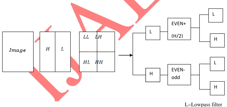
68 INTERNATIONAL JOURNAL OF ADVANCES IN ENGINEERING RESEARCH same two pixels. The four bands obtained are LL, LH, HL, and HH which is shown in Fig 1.The LL band is called as approximation band, which consists of low frequency wavelet coefficients, and contains significant part of the spatial domain image. The other bands are called as detail bands which consist of high frequency coefficients and contain the edge details of the spatial domain image. Integer wavelet transform can be obtained through lifting scheme. It is technique to convert DWT coefficients to Integer coefficients without losing information .bands are called as detail bands which consist of high frequency coefficients and contain the edge details of the spatial domain image. Integer wavelet transform can be obtained through lifting scheme. It is technique to convert DWT coefficients to Integer coefficients without losing information.
First stage IWT is as follows:
“H=Co−Ce,L=Ce+⌊H2⌋” (1)
Where Co = pixels in odd columns & Ce = pixels in even columns,
The first stage leads to the next stage processes that involve HP & LP filter banks to find IWT coefficients. It results in four sub bands [LL, LH, HL and HH] in which [LL] sub band has highly sensitive information. The rest of the bands have the in depth of hidden image information.
Second stage IWT is as follows:
“LH=Lodd-Leven, LL=Leven+[LH2] ” (2)
“HH=Hodd-Heven, HH=Heven+[HL2]” (3)
H L
EVEN+
(H/2)
EVEN-odd
H H L
L
L=Lowpass filter
H=Hipass filter
International Journal of Advances in Engineering Research http://www.ijaer.com (IJAER) 2015, Vol. No. 10, Issue No. II, August e-ISSN: 2231-5152/ p-ISSN: 2454-1796
69 INTERNATIONAL JOURNAL OF ADVANCES IN ENGINEERING RESEARCH Where Hodd = H band's odd row, Lodd = L band's odd row, Heven = H band's even row and Leven = L band's even row.
Step1: Column wise processing to get H and L
“ H = (Co-Ce)” (4)
“L = (Ce- [H/2])” (5)
Where Co and Ce is the odd column and even column wise pixel values Step 2: Row wise processing to get LL, LH, HL and HH, Separate odd and even rows of H and L, Namely, Hodd - odd row of H Lodd - odd row of L Heven- even row of H Leven- even row of L “ LH = Lodd-Leven” (6)
“LL = Leven – [LH /2 ]” (7)
“HL = Hodd – Heven” (8)
“HH = Heven – [HL /2 ]” (9)
A. Reverse Lifting scheme in IWT
Inverse Integer wavelet transform [IWT] is formed by Reverse lifting scheme. Procedure is similar to the forward lifting scheme.
B. LSB Embedding
International Journal of Advances in Engineering Research http://www.ijaer.com (IJAER) 2015, Vol. No. 10, Issue No. II, August e-ISSN: 2231-5152/ p-ISSN: 2454-1796
70 INTERNATIONAL JOURNAL OF ADVANCES IN ENGINEERING RESEARCH message. Mathematically pixel value ‘P’ of the selected pixel for storing the k-bit message Mk is modified to form the stego pixel ‘Ps’ as follows.
“Ps=P-mod (P, 2k) + Mk” (10)
The embedded message bits can be recovered by following equation.
“Mk=mod (Ps, 2k)” (11)
One method to improve the quality of the LSB substitution is Optimal Pixel adjustment Process (OPAP) [2].
C. Optimal Pixel adjustment Process
The proposed Optimal Pixel adjustment Procedure[OPAP] .it can reduces the error caused by the LSB substitution method. In OPAP method the pixel value is adjusted after the encrypted data is hidden. It is done to improve the quality of the stego image without disturbing the hidden data.
D. Adjustment Process
Let ‘ n ’ LSB's be substituted in each pixel. Let ' d '= decimal value of the pixel after the substitution,
'd1'= decimal value of last n bits of the pixel & 'd2'= decimal value of ' n' bits hidden in that pixel. If(d1~d2)<=(2^n)/2
then no adjustment is possible in that pixel. Else
If(d1<d2) d = d – 2^n . If(d1>d2) d = d + 2^n .
This d is converted to binary and written back to pixel.
PROPOSED METHODOLOGY
International Journal of Advances in Engineering Research http://www.ijaer.com (IJAER) 2015, Vol. No. 10, Issue No. II, August e-ISSN: 2231-5152/ p-ISSN: 2454-1796
71 INTERNATIONAL JOURNAL OF ADVANCES IN ENGINEERING RESEARCH
fif
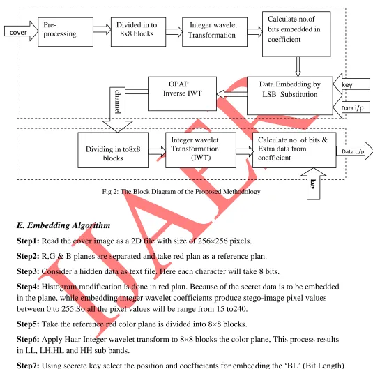
Fig 2:The Block Diagram of the Proposed Methodology
E. Embedding Algorithm
Step1: Read the cover image as a 2D file with size of 256×256 pixels.
Step2: R,G & B planes are separated and take red plan as a reference plan.
Step3: Consider a hidden data as text file. Here each character will take 8 bits.
Step4: Histogram modification is done in red plan. Because of the secret data is to be embedded in the plane, while embedding integer wavelet coefficients produce stego-image pixel values between 0 to 255.So all the pixel values will be range from 15 to240.
Step5: Take the reference red color plane is divided into 8×8 blocks.
Step6: Apply Haar Integer wavelet transform to 8×8 blocks the color plane, This process results in LL, LH,HL and HH sub bands.
Step7: Using secrete key select the position and coefficients for embedding the ‘BL’ (Bit Length) length data using LSB substitution. Here data is embedded only in LH, HL and HH sub band. Data isn't embedded in LL because they are highly sensitive and also maintain good visual quality after hiding data. An example for secrete key.
Pre- processing
Divided in to 8x8 blocks
Integer wavelet Transformation
Calculate no.of bits embedded in coefficient
Data Embedding by LSB Substitution OPAP
Inverse IWT
cha
nne
l
Dividing in to8x8 blocks
Integer wavelet Transformation
(IWT)
Calculate no. of bits & Extra data from coefficient key key key Data o/p key
Data i/p
International Journal of Advances in Engineering Research http://www.ijaer.com (IJAER) 2015, Vol. No. 10, Issue No. II, August e-ISSN: 2231-5152/ p-ISSN: 2454-1796
72 INTERNATIONAL JOURNAL OF ADVANCES IN ENGINEERING RESEARCH Step8: Take inverse wavelet transform to each 8×8 block for reference color plane to produce stego image.
(12)
F. Extraction Algorithm
Step 1: Read the Stego image as a 2D file with size of 256 ×256 pixels.
Step 2: R,G &B planes are separated
Step 3: Take Red as a reference color plane is divided into 8×8 blocks.
Step 4: Apply Haar Integer wavelet transform to 8×8 blocks to the color plane, this process results LL, LH, HL and HH sub bands.
Step 5: Using key select the position and coefficients for extracting the ‘BL’ length data.
VALIDATION
In validation we are taking some snapshots of our project demo also calculating Mean Square Error(MSE)and Peak Signal to Noise Ratio(PSNR)values. In stego image a performance measure means of two parameters namely, Mean Square Error(MSE) and Peak Signal to Noise Ratio (PSNR).The MSE is calculated by using the equation.
(13)
where M :number of rows and N:number of columns in the input image.
The Peak Signal to Noise Ratio (PSNR) is expressed as in db. PSNR calculated by using below equation .
International Journal of Advances in Engineering Research http://www.ijaer.com (IJAER) 2015, Vol. No. 10, Issue No. II, August e-ISSN: 2231-5152/ p-ISSN: 2454-1796
73 INTERNATIONAL JOURNAL OF ADVANCES IN ENGINEERING RESEARCH Where R is the maximum fluctuation in the input image data type. As we know ideally MSE value should be small and PSNR value should be very high.
RESULTS AND DISCUSSION
In this present implementation, Monalisa and lenna 256×256 × 3 color digital images and gray scale image have been taken as cover images, as shown in Figure 3&4- a, b, c ,d,e,f tested with various secrete keys. The effectiveness of the stego process proposed has been studied by calculating MSE and PSNR for t he two digital color images and gray level image values are tabulated.
fig:3(a)&(b)Monalisa Gray Image & transformation fig:4(a)&(b)Lenna gray & transformed image
Fig:3(c)&(d)monalisa color image and its transformation Fig4(c)&4(d)Lenna color image its transformation
International Journal of Advances in Engineering Research http://www.ijaer.com (IJAER) 2015, Vol. No. 10, Issue No. II, August e-ISSN: 2231-5152/ p-ISSN: 2454-1796
74 INTERNATIONAL JOURNAL OF ADVANCES IN ENGINEERING RESEARCH
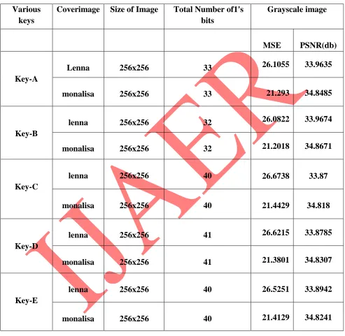
Table -1 MSE,PSNR for fixed Gray Scale Image
Various keys
Coverimage Size of Image Total Number of1's bits
Grayscale image
MSE PSNR(db)
Key-A
Lenna 256x256 33 26.1055 33.9635
monalisa 256x256 33 21.293 34.8485
Key-B
lenna 256x256 32 26.0822 33.9674
monalisa 256x256 32 21.2018 34.8671
Key-C
lenna 256x256 40 26.6738 33.87
monalisa 256x256 40 21.4429 34.818
Key-D
lenna 256x256 41 26.6215 33.8785
monalisa 256x256 41 21.3801 34.8307
Key-E
lenna 256x256 40 26.5251 33.8942
International Journal of Advances in Engineering Research http://www.ijaer.com (IJAER) 2015, Vol. No. 10, Issue No. II, August e-ISSN: 2231-5152/ p-ISSN: 2454-1796
75 INTERNATIONAL JOURNAL OF ADVANCES IN ENGINEERING RESEARCH
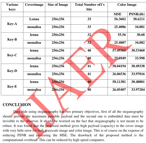
Table -2 MSE,PSNR for Color Image
Various keys
Coverimage Size of Image Total Number of1's bits
Color Image
MSE PSNR(db)
Key-A
Lenna 256x256 33 56.3602 30.6211
monalisa 256x256 33 25.4086 34.081
Key-B
lenna 256x256 32 55.56 30.68
monalisa 256x256 32 25.4007 34.082
Key-C
lenna 256x256 40 57.49365 30.53460
monalisa 256x256 40 25.8949 33.998
Key-D
lenna 256x256 41 58.04194 30.49338
monalisa 256x256 41 26.06536 33.97016
Key-E
lenna 256x256 40 58.11381 30.48801
monalisa 256x256 40 26.05407 33.97204
CONCLUSION
Data hide using steganography has two primary objectives, first of all the steganography should provide the maximum possible payload and the second one is embedded data must be invisible to the observer. It should be worried on the fact that steganography is not meant to be robust. It was found that the proposed method gives high payload (capacity) in the cover image with very little error for both grayscale image and color image. This is of course on the expense of reducing PSNR and increasing the MSE. The drawback of the proposed method is the computational overhead.This can be reduced by high speed computers.
REFERENCES
International Journal of Advances in Engineering Research http://www.ijaer.com (IJAER) 2015, Vol. No. 10, Issue No. II, August e-ISSN: 2231-5152/ p-ISSN: 2454-1796
76 INTERNATIONAL JOURNAL OF ADVANCES IN ENGINEERING RESEARCH [2] C. Chan and L. M. Cheng, "Hiding data in images by simple LSB substitution," Pattern Recognition, pp. 469-474, Mar. 2004.
[3] Changa, C. Changa, P. S. Huangb, and T. Tua, "A Novel bnage Steganographic Method Using Tri-way Pixel-Value Differencing,” Journal of Multimedia, Vol. 3, No.2, June 2008.
[4] H. H. Zayed, "A High-Hiding Capacity Technique for Hiding Data in images Based on K-Bit LSB Substitution," The 30th International Conference on Artificial Intelligence Applications (ICAIA - 2005) Cairo, Feb. 2005.
[5] A. Westfeld, "F5a steganographic algorithm: High capacity despite better steganalysis," 4th International Workshop on Information Hiding, pp.289-302, April 25-27, 2001.
[6] H. W. Tseng and C. C. Chnag, "High capacity data hiding in jpegcompressed images," Informatica, vol. 15, no. I, pp. 127-142,2004.
[7] P. Chen, and H. Lin, "A DWT Approach for bnage Steganography,"International Journal of Applied Science and Engineering 2006. 4, 3:275:290.
[8] Lai and L. Chang, "Adaptive Data Hiding for bnages Based on Harr Discrete Wavelet transform," Lecture Notes in Computer Science,Volume 4319/2006.
[9] S. Lee, C.D. Yoo and T. Kalker, "Reversible image watermarking based on integer-to-integer wavelet transform," IEEE Transactions on Information Forensics and Security, Vol. 2, No.3, Sep. 2007, pp. 321-330.