The Effect of Process Parameter on Weld Depth
in GMA Welding Process
Tarun Patel Prof. Saumil C Patel
PG Scholar Assistant Professor
Department of Mechanical Engineering Department of Mechanical Engineering
LDRP-ITR, Gandhinagar, Gujarat, India LDRP-ITR, Gandhinagar, Gujarat, India
Abstract
GAS METAL ARC welding (GMAW) is a process that melts and joins metals by heating them with an arc established between a continuously fed filler wire electrode and the metals. The process is used with shielding from an externally supplied gas and without the application of pressure. The American Welding Society refers to the process Gas Metal Arc Welding process to cover arc lengths of electrode and the feeding of the wire are automatically controlled. inert as well as active shield gasses. GMAW is basically a semi-automatic process, in which the Taguchi Technique is used to plan the experiments. The Taguchi method has become an influential tool for improving output during research and development. Taguchi strongly recommends for multiple runs, is to use the signal-to-noise (S/N) ratio for the same steps in the analysis. In this research work of Gas Metal Arc Welding (GMAW) show the effect of Current (A), Voltage (V), Gas Flow rate (Ltr/min) and on weld depth of ST-37 low carbon alloy steel material. In this Experiment we done Experiment by using L9 orthogonal Array to find out weld depth and also perform confirmatory Experiment to find out optimal run set of current, voltage speed and gas flow rate.
Keywords: GMA Welding, Orthogonal Array, S/N ratio, ST-37
_______________________________________________________________________________________________________
I.
INTRODUCTION
GMA welding is also recognized by gas metal arc welding. It is a semi-automatic process by which the arc length and feeding of wire into the arc can be controlled automatically and operator skills required to positioning the gun at a correct angle and moving it along the seam at a controlled travel speed in the metal transfer depends upon modular and spray transfer. In the 1920’s, the basic concept of GMAW was introduced but it was not commercially available until 1948[1].
Primarily it was considered to be, fundamentally, a high-current density, small diameter, bare metal electrode process using an inert gas for arc shielding. The application of this process was for welding aluminum and As a result, the term MIG (Metal Inert Gas) welding was used and till now a days. Subsequent process developments included operation at low-current densities and pulsed direct current, application to a broader range of materials, and the use of reactive gases (particularly CO2) and gas mixtures. The commercial metals like carbon steel low alloy and high alloy steels, stainless steels, aluminum, copper, titanium, zirconium, nickel alloys can be welded by nuclear welding. By this process thickness range weld joints can be possible in any welding positions. Speed through a welding gun, it picks up electric current from copper. Contact tube which is electrically connected to the DC power source and a shielding gases like argon, Helium, Carbon Dioxide, Carbon Dioxide-Argon mixture, Argon-Helium mixture. Shielding Gases are also use to cool down the gun. MIG Welding is use to increase Productivity and consistency of Quality [2].
II.
LITERATURE REVIEW
Manoj Singla et al Parametric Optimization of Gas metal arc Welding Processes by Using factorial design approach Various welding variables which influence WDA were identified and their quantitative influence on the same was investigated Welding current was found to be most influencing variable to WDA [2].
H. R. Ghazvinloo et al Study on effect of process variables on fatigue and impact behavior and bead penetration of robotic MIG welded AA6061 Aluminum alloy joints. The fatigue life of weld metal decreased clearly with increasing arc voltage between 20 and 26 V and welding current between 110 and 150 A whereas the effect of welding speed on fatigue life was reversed to other parameters [3].
Gautama Kocher experimental analysis in MIG welding with is 2062e250 a steel with various effects. The depth of penetration of the weld bead is of high importance because it has a direct influence on weld strength. An increase in welding speed at constant wire speed rate and constant arc voltage and welding current, results decrease in the heat input and hence, decrease in the depth of penetration and the width of the weld bead in the single pass weld [4].
M. Aghakhani et al Parametric Optimization of Gas Metal Arc Welding Process by Taguchi method on Weld dilution. This paper has presented an application of the parameter design of the Taguchi method in the optimization in the GMAW parameters. A five -factor five level Taguchi experimental design was used to study the relationships between the weld dilution and the five controllable input welding parameters such as, wire feed rate, welding voltage, nozzle-to-plate distance, welding speed, gas flow rate [5].
III.
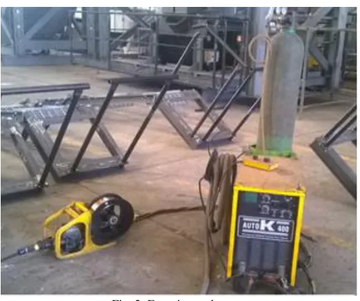
EXPERIMENTAL SETUP
Fig. 2: Experimental set up
Table -1: Technical specification Technical specification Open circuit voltage, V DC 53 v
Welding current range, A 60 – 400 Dimensions, l x w x h, mm 685 x 360 x 755
Weight, Kg 121
Wire feeder
Drive system DC motor
Speed control Step less Wire feed speed, m/min 1 – 16
Wire diameter, mm 0.8 – 1.2
Wire type MS / Al / FC
Weight, Kg 7
Work piece material.
Low carbon steel ST 37.
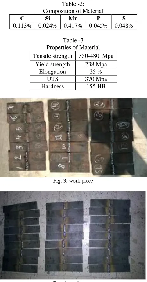
Table -2: Composition of Material
C Si Mn P S
0.113% 0.024% 0.417% 0.045% 0.048% Table -3
Properties of Material Tensile strength 350-480 Mpa
Yield strength 238 Mpa Elongation 25 %
UTS 370 Mpa
Hardness 155 HB
Fig. 3: work piece
Fig. 4: work piece
The experiment was conducted at the Apollo earth mover pvt. Ltd. Material is cut on proper dimension and grinding the material for surface finish and Amery stone are used for good finishing after that welding expert welded two piece and put them for cooled in air.
IV.
TAGUCHI ANALYSIS
Taguchi technique is used to increases the output and reduced the cost of the products. The Taguchi Design is based on orthogonal array. Taguchi design recognizes the control factors to minimize the effect of Noise factor. Orthogonal array helps to reduce the time and cost of the experiment. The Signal-to-Noise (S/N) Ratio which are log function of required output which is the objective function to be optimized [6].
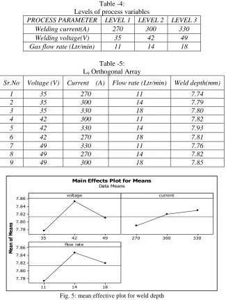
Table -4:
Levels of process variables
PROCESS PARAMETER LEVEL 1 LEVEL 2 LEVEL 3
Welding current(A) 270 300 330
Welding voltage(V) 35 42 49
Gas flow rate (Ltr/min) 11 14 18
Table -5: L9 Orthogonal Array
Sr.No Voltage (V) Current (A) Flow rate (Ltr/min) Weld depth(mm)
1 35 270 11 7.74
2 35 300 14 7.79
3 35 330 18 7.80
4 42 300 11 7.82
5 42 330 14 7.93
6 42 270 18 7.81
7 49 330 11 7.76
8 49 270 14 7.82
9 49 300 18 7.85
Fig. 5: mean effective plot for weld depth
From above Fig. 5 mean is average value for reading taken for particular parameter. From graph, mean value is maxi-mum (7.85) for 42 V and minimum (7.70) for 35 V. Mean value is maximum (7.85) for 14 Ltr/min flow rate and minimum (7.70) for 11 Ltr/min flow rate...
Delta is difference of maximum value and minimum value. Delta value is maximum for voltage (0.09) and minimum (0.04) for current. So that effect of voltage is maximum and effect of current is minimum on weld depth.
Fig. 6: S/N ratio for weld depth 49 42 35 7.86 7.84 7.82 7.80 7.78 330 300 270 18 14 11 7.86 7.84 7.82 7.80 7.78 voltage M ea n of M ea ns current flow rate
Main Effects Plot for Means Data Means 49 42 35 17.900 17.875 17.850 17.825 17.800 330 300 270 18 14 11 17.900 17.875 17.850 17.825 17.800 voltage M ea n of S N ra tio s current flow rate
Main Effects Plot for SN ratios Data Means
Fig. 6 shows the response curve for S/N ratio, the largest S/N ratio was observed at voltage (42), current (330) and flow rate (14), which optimum parameter are setting for largest weld depth from delta values as mention above, maximum (0.09) for flow rate and minimum (0.04) for voltage. Parameter voltage is most significant parameter and current is least significant for weld depth.
The term optimum set of parameters is reflects only optimal combination of the parameters defined by this experiment for highest weld depth. The optimum setting is determined by choosing the level with the highest S/N ratio. Referring Fig.6 and Table 4, the response curve for S/N ratio, the highest performance at set 42 voltage, 14 Ltr/min flow rate, 330 A current and which is optimum parameter setting for weld depth.
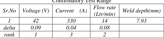
Table -6
Confirmatory Test Range
Sr.No Voltage (V) Current (A) Flow rate
(Ltr/min) Weld depth(mm)
1 42 330 14 7.93
delta 0.09 0.04 0.08
rank 1 3 2
Predict Performance at Optimum Setting: A.
Using optimum set of parameters, which was achieved by response curve analysis was used for prediction by Minitab software. Minitab software for Taguchi method of optimization was suggested weld depth 7.93mm and S/N ratio was 17.95 for optimum set of parameter as shown in Table 6.
Table -7 Predicted Performance
S/N Ratio Mean
17.95 7.90
Conformation Test: B.
In this step of the process was to run confirmation experiments to verify the welding parameter setting really produce optimum performance and to evaluate the predictive capability of the Taguchi method for GMA welding performance. The optimum parameters were settled in the welding and performance was measured for that set of parameter. Table VIII shows performance was compared with predicated performance and was found that the experimental value was nearer to the predicated value.
Table -8
Comparison between Predicated Value and Experimental Value
Ultimate tensile strength Predicated Value Experimental Value
7.89 7.16
V.
CONCLUSION
The feasibility of using Taguchi method to optimize selected GMA welding parameter for highest performance was investigated The results of the Taguchi experiment identify that 42 voltage, 330 current, flow rate 14 Ltr/min are optimum parameter setting for weld depth. Welding performance is mostly influenced by voltage and is least influenced by current confirmation experiment was done using optimum combination showed that weld depth was found by experiment also closer to the predicated value.
REFERENCES
[1] S.Utkarsh, P. Neel, Mayank T Mahajan, P.Jignesh, R. B.Prajapati “Experimental Investigation of MIG Welding for ST-37 Using Design of
Experiment” IJSRP Volume 4, Issue 5, May 2014.ISSN 2250-3153
[2] Manoj Singla, Dharminder Singh, Dharmpal Deepak “Parametric Optimization of Gas metal arc Welding Processes by Using factorial design
approach” JMMCE Vol. 9, No.4, pp.353-363, 2010
[3] H. R. Ghazvinloo, A. Honarbakhsh Raouf1 and N. Shadfar “A Study on Effect of Process Variables on Fatigue and Impact Behavior and Bead
Penetration of Robotic MIG Welded AA6061 Aluminum Alloy Joints” IIW International Congress on Welding & Joining pp. 270 – 277
[4] Gautama Kocher “experimental analysis in MIG welding with is 2062e250 a steel with various effects” IJET April-June, 2012, 158-162
[5] M. Aghakhani, E. Mehrdad, and E. Hayati.” Parametric Optimization of Gas Metal Arc Welding Process by Taguchi Method on Weld Dilution”
IJMO Vol. 1, No. 3, August 2011
[6] S. R. Patil, C. A. Waghmare “Optimization of MIG Welding Parameters for Improving Strength of Welded Joints” IJERS, E-ISSN2249–8974
[7] Srinivas Athreya, Dr Y.D.Venkatesh “Application of Taguchi Method for Optimization of Process Parameters in Improving the Surface Roughness of
Lathe Facing Operation” IRJES Volume 1, Issue 3, ISSN 2319-183X,
[8] Jožef Horvat, Jurij Prezelj, Ivan Polajnar, Mirko Čudina, “Monitoring Gas Metal Arc Welding Process by Using Audible Sound Signal” Journal of
![Fig. 1: GMA welding process [8]](https://thumb-us.123doks.com/thumbv2/123dok_us/8870682.1813736/1.612.140.473.536.725/fig-gma-welding-process.webp)