Parametric Study of the Load Carrying Capacity of Functionally Graded
Concrete of Flexural Members
Han Aylie
1, Buntara Sthenly Gan
2,*, Sholihin As’ad
3, M. Mirza Abdillah Pratama
41Department of Civil Engineering, Diponegoro University, Semarang, Indonesia.
2Department of Architecture, College of Engineering, Nihon University, Koriyama, Japan.
3Department of Civil Engineering, Sebelas Maret University, Surakarta, Indonesia.
4
Researcher, Department of Civil Engineering, Diponegoro University, Semarang, Indonesia.
Received 09 August 2015; received in revised form 15 September 2015; accepted 20 September 2015
Abstract
Steel reinforced concrete members in bending acquire their load carrying capacity from the integration
between concrete compression and steel tensile strength. The codes neglect the concrete tensile capacity since it is
relatively small compared to the compressive strength. Hypothetically, if a low concrete strength is assigned to the
layers in tension, it leads to economical and environmental advantages. A method for producing functionally
graded concrete (FGC) having a gradation in compressive strength and stiffness throughout the depth of a member
was developed. Uniaxial compression tests on cylindrical FGC specimens were conducted and verified
numerically using finite element models. We suggest that the compressive strength of FGC approaches the lower
grade concrete layers while the stiffness properties follow the higher grade concrete layers. This potential could be
exploited for the flexural member, through optimising of material use while improving the serviceability of the
member.
Keywords: Functionally Graded Concrete; Load Carrying Capacity; Flexural Member; Finite Element Analysis
1.
Introduction
Functionally graded materials (FGM) have become increasingly popular over the past decade due to their potential in
cost optimization and enhancement in material performance. An extensive study on bamboo as a naturally graded material
was conducted, finding that the bamboo fibers had a radial fibre distribution outward through the thickness of the section.
This graded section influenced the response to tensile, torsion and flexural stress positively [1–3]. Contradicting the
assumptions used in analyses and design, concrete is by nature a graded material [4,5]. This non-homogeneous behaviour is
a result of mixing, and especially the casting process inducing segregation and an isometry in the material. Additional factors
are bleeding, and microcracking due to premature water evaporation at the exposed surfaces. The mode of gradation,
however, could not be controlled and follows a decreasing strength pattern towards the top layers of the member.
Learning from nature, research was aimed to produce functionally graded ceramic, metal and cementitious products. To
create the differentiation in strength for cementitious materials, fibres were added to the mix. The percentage of fibres was
gradually increased throughout the depth of the member. The fibres used in these studies were methyl cellulose,
polypropylene/polyethylene (PP), polyvinylalcohol (PVA) and steel fibres [6–9]. Cellulose in combination with synthetic
fibres was used to produce graded cement corrugated sheets [10].
1.1 Proposed production methods for FGC
The preparation of functionally graded cementitious materials faces one major challenge: creating a smooth transition
between layers. When this primary goal is not achieved, a laminated, rather than graded product will result, and weak
transition areas between layers will influence the behaviour of the material. From the state of basic materials, the fabrication
is distinguished in the gaseous, solid and liquid process. The method introduced by Kawasaki and Watanabe [11] and
Kieback et al. [12] makes use of the powder metallurgical process. Kawasaki and Watanabe [11] developed a method for
creating graded ceramics by the addition of metal powder. The mixing of the material is mechanically controlled by two
suspension containers, the output of which can be regulated by a valve. The material is mixed with ethanol in a larger
container and sprayed with a nozzle into a preheated chamber. Kieback et al. [12] developed a similar mechanism, but the
heating process was performed within the two individual containers before entering the mixing chamber. The preheated
mixture was further discarded by a high-pressure nozzle.
Dias et al. [10] produced a functionally graded fibre cement element based on the liquid method, in combination with
the Hatschek process. The cement material is formed in a slurry; the gradation is controlled by a differentiation in fiber
content.
Chen et al. [6], Shen et al. [7] and Gan et al. [13] approached the production of functionally graded concrete by the
liquid process and added superplasticizers to improve flowability of the concrete mixture. Chen et al. [6] regulated the
variation in strength by adding methylcellulose fibres and Shen et al. [7] used PVA fibres, while Gan et al. [13] varied the
cement content relative to the aggregates. Chen et al. [6] and Shen et al. [7] used a fabricated co-extruder to produce concrete
layers with differentiations in strength. The layers were stacked and pressed to form a strong inter-layer bond through
hydration and pressure, resulting in a continuous beam. The method developed by Gan et al. [13] made use of a mechanic
tamping rod with a standardized length to control the depth of the compacted layers. All the procedures were versatile in
creating a graded material having both strength and stiffness properties varying along the depth of the member.
Jha et al. [14] outlined the current state on functionally graded material with an emphasis on metal and ceramic products.
Studies on functionally graded concrete, however, are very limited. This study is based on laboratory data that are further
utilised in finite element analysis to explore the optimization aspect of FGC.
1.2 Functionally Graded Concrete (FGC)
Numerical and finite element methods (FEM) are options to acquire information that could not otherwise be obtained
from experimental studies. In analytical studies of reinforced concrete structures, it is considered that the entire member
possesses a uniform material property’s behaviour. Stroeven and Hu [4] and Hidayat et al. [5] contradict this assumption. It
was shown that when the structural element has a significant height-to-width ratio, such as is the case for columns and deep
beams, the concrete properties such as the strength and material stiffness vary with the depth of the member.
Experimental research conducted by Hidayat et al. [15] using the rebound hammer on an existing structural beam
element showed that the beam possessed a non-uniform compressive strength as a function of the distance from the extreme
bottom fibres. The beam’s compressive strength at the top fibres was lower than at the bottom fibres of the element. The
study was also focused on a laboratory-produced concrete beam with a designed strength of 60 MPa with dimensions of 600
x 600 x 200 mm. This sample was used as an implementation prototype for simulating the behaviour of a reinforced concrete
element in the field. The panel was subjected to testing by the Ultrasonic Pulse Velocity (UPV) and rebound hammer. The
cylinder compressive strength fc’ was obtained by core drilling of the panel; the cylindrical specimens measuring 100 x 200
mm were tested in the laboratory. The concrete panel had a strength of 60 MPa only at the bottom fibres and decreased in
Further, FGC samples were artificially produced in the laboratory and tested to obtain the stress and strain responses as
a function of layer heights [13,16], while Han et al. [17] combined the experimental test results with finite element analysis
(FEA). The FEA study on the FGC members resulted in an approach to model the gradation in strength as finite layers,
having a differentiation in material properties. The input for the model consisted of the strength, the Poisson’s ratio and
initial stiffness of each layer as a function of its coordinate on the reference axes, situated at the extreme bottom fibres of the
specimen. It is now possible to simulate an FGC member based on laboratory-tested specimens.
2.
Functionally Graded Concrete of Flexural Members
For flexural members of FGC, low tensile strength in the tension areas will not influence the load carrying capacity of
the member, but the overall stiffness will have a positive impact on the serviceability under working load conditions. To
conduct a parametric study of the load carrying capacity of FGC beams in bending, several FEM models are used for
sensitivity analyses, and comparisons to FGC behaviour are investigated.
2.1 Compressive strengths of monolith concrete
The laboratory-based specimens validated by the FEM had a compressive strength of 20 MPa on the top fibres and a 60
MPa compressive strength at the bottom. In between the top and bottom fibres, the strength gradually increased. The
stress-strain response of the FGC compared to the uniform 20 and 60 MPa specimens is shown in Fig. 1.
Fig. 1 Stress-strain responses of compressive FGC [13,17]
The notation G was used to identify the graded specimen while P was used to distinguish the uniform specimens. The
uniform P specimens followed the response as mandated by the CEB-fib code (Bulletin 70: [18]). However, the FGC
specimen deviated significantly from the predicted curves. It was expected that the stress-strain response of this material will
somehow fall within the boundaries of the P20 and P60 curves, both regarding strength and stiffness. What was observed is
that the FGC material had a strength approaching only 20 MPa, combined with an initial stiffness close to P60 [13,17].
2.2 Constitutive Material
Three concrete material properties, namely the Poisson’s ratio υ, the tensile strength characteristic fc and the
compressive strength characteristic fc’ for each layer were adopted from Hidayat et al. [5] and were used as inputs for the
FEM. The section’s height was converted to the laboratory specimen height to obtain a close approximation to the
experimental condition. The additional material properties, the elastic modulus E and the stress-strain relationship of the concrete, were generated by data interpolation. The failure criterion was based on the Max-stress failure envelope that
criteria of Ottosen [19] and Speck [20], implemented by the Bulletin 70 of the fib except that the strength increases in biaxial
compression from the confining effect being neglected. The failure criterion of the steel was designated by the Von Mises
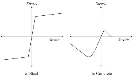
model. The constitutive material model for the concrete was approached by the CEB-fib code (fib Bulletin 70) while the steel
response followed a bi-linear path, as shown in Fig. 2.
Fig. 2 Typical stress-strain relationship for steel and concrete materials
2.3 Simply supported beam under two-point symmetrical loadings
To study the load carrying capacity and behaviour of FGC members in bending, a simply supported 300 x 500 mm
section with a length of 6.5 m is created. The beam has a clear span of 6 m. The member is subjected to a pure bending mode
produced by a two-point loading system having a distance of 2 m apart, as seen in Fig. 3. The point loads P are situated at a
relatively far distance from the support, which served the purpose that with a relatively small load, a large flexural moment,
sufficient to collapse the concrete section in bending, is produced while minimizing the effect of shear stress on the failure
mode. The beam was singly reinforced in tension by 4D22 bars having a yield stress of fy = 410 MPa, situated at a distance
of 62.5 mm from the extreme concrete fibres in tension.
Fig. 3 Beam model for parametric study
Due to the geometry and loading symmetry of the beam, one-half of the beam was analysed by implementing roller at
the mid-span, thus minimizing the number of nodes and elements, and conserving running time. The centre of the beam was
restrained against horizontal movements having one degree of freedom in the vertical direction. The elements are modelled
as isotropic, isoparametric Quad-8 plane stress elements. We used a non-linear material software that accommodate the
material behaviour differentiation with the tangent stiffness method. In modelling, the steel bar is represented by the
distributed or smeared-in method, a technique where the steel properties are incorporated into the properties of the second
concrete layer element. This method has been proven sufficiently accurate in predicting the behaviour of flexural members
[21–22]. Since the main focus was analysing the behaviour of FGC in flexure, details on bond, interlocking and shear
2.4 Meshing convergences of uniform beams
To evaluate the accuracy of meshing in the FEM model, a sensitivity analysis on the refinement of the model was
performed. The FEM mesh of the half-beam model is subdivided by 7x21, 15x164, 32x208 and 32x408 meshes in vertical
and horizontal directions respectively. The models were labelled M1, M2, M3, M4, respectively. All the models have a
uniform compressive strength of 20 MPa of concrete and under reinforcement condition is designed for the 4D22 steel bars
by assuming the failure is due to yielding of the steel. The mesh refinements schemes are shown in Fig. 4; the resulting
ultimate load and displacement are shown in Fig. 5 and the deviations between two models can be seen in Table 2.
Fig. 4 Mesh refinement schemes of uniform concrete half-beams
Fig. 5 Load carrying capacity of mesh refined uniform concrete beams
Table 2 FEM results of mesh refined uniform concrete beams
Model
Mesh Subdivision
(V x H)
Ultimate Load (kN) Load Deviation (%) Displacement at Ultimate Load (mm) Displacement Deviation (%)
M1 7 x 21 663.36 --- 32.480 ---
M2 15 x 164 414.25 -37.6 23.836 -26.6
M3 32 x 208 350.87 -15.3 19.525 -18.1
M4 32 x 408 320.80 -8.6 18.533 -5.1
It can be observed that the M3 has a relatively lower deviation rate of loading and displacement results compared to the
M4 results. While the M4 demonstrated a convergence and improvement on the M3, the running time for the M4 model
increasing exponentially. To reduce the efforts of computational cost reasonably, the meshing scheme of M3 was selected
2.5 Layer mesh requirement of graded concrete beams
Since the available commercial FEM software cannot incorporate the functionally graded material directly into the
model, the nonhomogeneity of the beam section is approximated by dividing the vertical mesh of the beam to assign layers
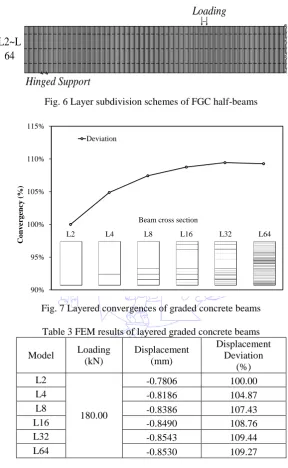
according to the functionally graded concrete strengths. Figure 6 shows the layer division schemes of the singly under
reinforced FGC half beam. The beam section was refined vertically by 2, 4, 8, 16, 32 and 64 layers, labelled by L2, L4, L16,
L32, L64, respectively. The load is fixed at 0.4 times of the ultimate load predicted, where the maximum vertical
displacements of each model are calculated, and the results can be seen in Fig. 7 and Table 3.
Fig. 6 Layer subdivision schemes of FGC half-beams
Fig. 7 Layered convergences of graded concrete beams
Table 3 FEM results of layered graded concrete beams
Model Loading (kN)
Displacement (mm)
Displacement Deviation
(%) L2
180.00
-0.7806 100.00
L4 -0.8186 104.87
L8 -0.8386 107.43
L16 -0.8490 108.76
L32 -0.8543 109.44
L64 -0.8530 109.27
It can be observed from Fig. 7 and Table 3 that a very close convergent state was reached by the model L32
approaching the model L64. While the model L64 demonstrated a small improvement on model 3, the running time
increased considerably. Therefore, the model L32 was adopted in the parametric studies. These 32 layers are utilised to
investigate the load carrying capacity of flexural FGC beams.
2.6 Parametric Study of flexural FGC beams
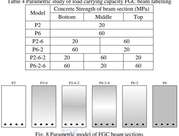
Table 4 shows four models of FGC beam and two models of uniform beam, for comparison. The uniform beams
labelled by P2 and P6 have a homogeneous concrete strength of 20 MPa and 60 MPa respectively. The graded beams were
distinguished as P2-6 and P6-2, having a graded concrete strength ranging from 20 to 60 MPa, and 60 to 20 MPa from the
L2~L
64
Hinged Support
Loading
R
o
ll
e
r
su
p
p
o
rt
90% 95% 100% 105% 110% 115%
Co
nv
ergency
(%
)
Deviation
L2 L4 L8 L16 L32 L64
bottom to the top, and the P2-6-2 and P6-2-6 beams having a graded concrete strength ranging from 20–60–20 MPa, and 60–
20–60 MPa from bottom to the middle and continuously further to the top surface of beam section. The reinforcement ratio
of the steel bars was ρ = 1.94 for the P2 model, and ρ = 3.44 for P6 model. All the beams were designed under-reinforced,
hence the failure is assumed to be due to yielding of steel bars.
Table 4 Parametric study of load carrying capacity FGC beam labelling
Model Concrete Strength of beam section (MPa)
Bottom Middle Top
P2 20
P6 60
P2-6 20 60
P6-2 60 20
P2-6-2 20 60 20
P6-2-6 60 20 60
Fig. 8 Parametric model of FGC beam sections
The results of load and displacement curves of the FGC beams model are depicted in Fig. 9. In the figure, P2 and P6
models show the uniform concrete with the lowest and highest ultimate load amongst the others. In addition, as seen from
the figure, the variation of two different concrete strengths that comprise three different layers of the P6-2-6 and P2-6-2
models only shows a slight deviation from the uniform beam section models of P6 and P2. A combination of two concrete
strengths such as P2-6 does not increase the ultimate load significantly, but the stiffness strength of the beam is increased, as
shown in the figure. Similarly, the combination of two concrete strengths of P6-2 shows an ultimate load of the beam in
between the uniform P2 and P6 models, while the stiffness of the beam also improved considerably.
If both P2-6 and P6-2 results are compared, it seems like the P6-2 model is superior to the P2-6 model, although both
models have the same constituents of material compositions. From the present parametric study, a better performance of
FGC flexural beam could be obtained by arranging the higher concrete strength side at the tensile part of the beam.
Fig. 9 Load displacement relationship of FGC beams
P2 P2-6 P2-6-2 P6-2-6 P6-2 P6
0 100 200 300 400 500 600 700 800
0 5 10 15 20 25 30
Loa
d
(k
N)
Displacement (mm)
P6
P6-2-6
P6-2
P2-6
P2-6-2
P2S
P6
P6-2-6
P6-2
P2-6
P2-6-2
3.
Conclusions
In practice, it was found that concrete members have a non-uniform mechanical property formation along the depth of
the beam section. A functionally graded concrete material can be produced by controlling its production process so that a
smooth transition between layers is created.
In the present study, the load carrying capacity of FGC flexural beams was investigated by means of finite element
modelling. The results show that:
(1)Mesh convergence schemes are necessary before conducting a parametric study using FEM.
(2) To apply the functionally graded conditions, layer meshing schemes are required to obtain accurate results.
(3) The composition of three layers FGC using two different concrete strengths has only a slight improvement or reduction
of the ultimate load, but changed the stiffness of the beams.
(4)A combination of two different concrete strengths shows significant changes in the stiffness and ultimate load of the FGC
beams.
(5) If two different concrete strengths are used, the higher concrete strength needs to be assigned to the layers where tension
is dominant in the FGC beams.
The availability of current commercial structural software cannot accommodate the direct implementation of the FGC
beams; hence the layer-wise approach could give reliable results after conducting the meshing and grading convergence tests
in advance.
These pioneering research works have provided a good view of FGC behaviour in flexural loading of beams. Assessing
the advantages of the FGC beams, two aspects are notable: cement reduction and serviceability performance. A reduction in
cement is not only cost-effective, but also has a positive impact on the environmental issue. Less cement means a reduction
in carbon emissions during concrete production. The FGC thus provides an excellent method to reduce cement content,
while maintaining the same level of serviceability with a negligible increase in required reinforcement.
References
[1] S. Amada, Y. Ichikawa, T. Munakata, Y. Nagase and H. Shimizu H., “Fiber texture and mechanical graded structures of bamboo,” Composites Part B: Engineering, vol. 28, no. 1-2, pp. 13-20, 1997.
[2] E. C. N. Silva, M. C. Walters and G. H. Paulino, “Modeling bamboo as a functionally graded material: lessons for analysis of affordable material,“ Journal of Material Science, vol. 41, no. 21, pp. 6991-7004, 2006.
[3] K.Ghavami, C. S. Rodrigues and S. Paciornik, “Bamboo: Functionally graded composite material,” Asian Journal of Civil Engineering, vol. 4, no. 1, pp. 1-10, 2015.
[4] P. Stroeven and J. Hu, “Gradient structures in cementitious materials,” Cement and Concrete Composites, vol. 29, no. 4, pp. 313-323, 2007.
[5] A. Hidayat, Purwanto, J. Puspowardojo and F. A. Aziz, “The influence of graded concrete strength on concrete element,” Procedia Engineering, vol. 125, pp. 1023-1029, 2015.
[6] Y. Chen, L. J. Struble and G. H. Paulino, “Fabrication of functionally graded-cellular structures on cement-based materials by co-extrusion,” Conference Proceedings of American Institute of Physics, Multiscale and Functionally Graded Materials, pp. 532-537, 2006.
[7] B. Shen, M. H. Hubler, G. H. Paulino and L. J. Struble, “Functionally-graded fiber-reinforced cement composite: Processing, microstructure, and properties,” Cement and Concrete Composites, vol. 30, pp. 663-673, 2008.
[9] M. Mastali, Z. Abdollahnejad, M. G. Naghibdehi and M. K. Sharbatdar, “Numerical evaluations of functionally graded RC slabs,” Chinese Journal of Engineering, vol. 9, pp. 1-20, 2014.
[10] C. M. R. Dias, H. Savastano Jr. and V. M. John, “Exploring the potential of functionally graded materials concept for the development of fiber cement,” Construction and Building Materials, vol. 24, pp. 140-146, 2009.
[11] A. Kawasaki and R. Watanabe, “Concept and P/M fabrication of functionally gradient materials,” Ceramic International, vol. 23, pp. 73-83, 1997.
[12] B. Kieback, A. Neubrand and H. Riedel, “Processing techniques for functionally graded materials,” Material Science Engineering, vol. 362, pp. 81-106, 2003.
[13] B. S. Gan, A. L. Han and M. M. A. Pratama, “The behavior of graded concrete, an experimental study,” Procedia Engineering, vol. 125, pp. 885-891, 2015.
[14] D. K. Jha, T. Kant and R. K. Singh, “A critical review of recent research on functionally graded plates,” Composite Structures, vol. 96, pp. 833-849, 2013.
[15] A. Hidayat, Purwanto, J. Puspowardojo and F. A. Aziz, “The influence of graded concrete strength on concrete element,” 5th Euro Asia Civil Engineering Forum Conference (EACEF-5), Surabaya, Indonesia, 2015.
[16] M. M. A. Pratama, “An experimental finite element approach to the behavior of graded concrete,” Master’s Thesis, Magister of Civil Engineering, Diponegoro University, 2015.
[17] A. Han, B. S. Gan and M. M. A. Pratama, “The influence of concrete compression strength gradation to the behavior of an element,” Proceeding of International Multi-Conference on Engineering and Technology Innovation (IMETI), Kaohsiung, Taiwan, 2015.
[18] Code-type models for concrete behavior, FIB Bulletin 70, 2013.
[19] N. S. Ottosen, “A failure criterion for concrete,” ASCE Journal of the Engineering Mechanics Division, vol. 103, no. EM4, pp. 527-535, 1977.
[20] K. Speck, “Beton unter mehraxialer beam spruchung-Ein material gesetz für Hochleistungs beton unter Kurzzeit belastung,” Ph.D. dissertation, Technische Universitat Dresden, Germany, 2008.
[21] H. G. Kwak and F. C. Filippou, “Finite element analysis of reinforced concrete structures under monotonic and cyclic loads,” Proceeding of 10th World Conference in Earthquake Engineering, Madrid, Spain, 1992.
![Fig. 1 Stress-strain responses of compressive FGC [13,17]](https://thumb-us.123doks.com/thumbv2/123dok_us/9828134.1968898/3.595.173.423.345.556/fig-stress-strain-responses-compressive-fgc.webp)