Yathiraj H U
et al
, International Journal of Computer Science and Mobile Applications,
Vol.2 Issue. 5, May- 2014, pg. 45-54 ISSN: 2321-8363
©2014, IJCSMA All Rights Reserved, www.ijcsma.com 45
Implementation of BCH Code (n, k)
Encoder and Decoder for Multiple
Error Correction Control
Yathiraj H U
1, Mahasiddayya R Hiremath
2Shree Devi Institute of Technology, Mangalore1 BTL Institute of Technology, Bangalore2 [email protected] 1, [email protected] 2
Abstract — In this paper we have designed and implemented (15, k) a BCH Encoder and decoder using VHDL for reliable data transfer in AWGN channel with multiple error correction control. The digital logic implementation of binary encoding of multiple error correcting BCH code (15, k) of length n=15 over GF (24) with irreducible primitive polynomial x4+x+1 is organized into shift register circuits. Using the cyclic codes, the reminder b(x) can be obtained in a linear (15-k) stage shift register with feedback connections corresponding to the coefficients of the generated polynomial. Three encoders are designed using VHDL to encode the single, double and triple error correcting BCH code (15, k) corresponding to the coefficient of generated polynomial. Information bit is transmitted in unchanged form up to K clock cycles and during this period parity bits are calculated in the LFSR then the parity bits are transmitted from k+1 to 15 clock cycles. Total 15-k numbers of parity bits with k information bits are transmitted in 15 code word. In multiple error correction method, we have implemented (15, 5 ,3 ) ,(15,7, 2) and (15, 11, 1) BCH encoder and decoder using VHDL and the simulation is done using Xilinx ISE 14.2.
Keywords- BCH, BER, SNR, BCH Encoder, Decoder VHDL, Error Correction, AWGN, LFSR
I. INTRODUCTION
In recent years there has been an increasing demand for digital transmission and storage systems. This demand has been accelerated by the rapid development and availability of VLSI technology and digital processing. It is frequently the case that a digital system must be fully reliable, as a single error may shutdown the whole system, or cause unacceptable corruption of data, e.g. in a bank account. In situations such as this error control must be employed so that an error may be detected and afterwards corrected. The simplest way of detecting a single error is a parity checksum, which can be implemented using only exclusive-or gates. But in some applications this method is insufficient and a more sophisticated error control strategy must be implemented.
To have a reliable communication through noisy medium that has an unacceptable bit error rate (BER) and low signal to noise ratio (SNR), we need to have Error Correcting Codes (ECC). The error correction is based on mathematical formulas, which are used by Error correcting codes (ECC). Error correction is taken place by adding parity bits to the original message bits during transmission of the data. Because of the addition of parity bits to message bits makes the size of the original message bits longer. Now this longer message bits is called “Code word”. This code word is received by the receiver at destination, and could be decoded to retrieve the original message bits. Error correcting codes are used in most of the digital applications, space and satellite communication and cellular telephone networks.
Yathiraj H U
et al
, International Journal of Computer Science and Mobile Applications,
Vol.2 Issue. 5, May- 2014, pg. 45-54 ISSN: 2321-8363
©2014, IJCSMA All Rights Reserved, www.ijcsma.com 46
II. BCH CODES
Multiple error correcting codes can be developed by the method of forming standard arrays, with the required value of H.D. >2t, t=number of errors in the received vector. More elegant methods however have been developed for t-error correcting codes, and these have resulted in BCH, RS, Golay, Reed-Muller, Simplex and other codes. Most of these codes are cyclic codes and are decoded by meggitt or error trapping decoders decoding of BCH, RS codes is rather complex, requiring solution of simultaneous equations and matrix inversion. Fortunately, some of these codes are also majority logic decodable and the decoders for them are very simple. So in this project we are encoding the BCH codes by using LFSR and decoding by majority logic decoders and meggitt decoder.
The BOSE-CHAUDHURI-HOCQUENGHEM (BCH) codes, discovered in 1959-60, are a class of cyclic codes with powerful error-correcting properties and well-known implementation algorithms. BCH (binary) codes may also be considered as a binary group code, where the necessary and sufficient conditions to be satisfied are:
(a) For a t-error correcting (n ,k)binary group code, an (n*r)=[HT] matrix exists, such that any 2t row vectors of the matrix are mutually independent, (r= n-k).
(b) For any positive integers m and t (t < 2m-1), a BCH code has the parameters: Block length n= 2m-1
No. Of parity check bits r= n-k ≤ m*t Minimum H.D. ≥ 2t+1
III. CONSTRUCTION OF BINARY BCH CODES
As the BCH code operate in Galois Field, it can be defined by two parameters that are length of code words (n) and the number of error to be corrected t.
A t-error-correcting binary BCH code is capable of correcting any combination of t or fewer errors in a block of n = 2m-1 digits. For any positive integer m ≥ 3 and t < 2m-1, there exists a binary BCH code with the following parameters. Block length: n = 2m- 1
Number of information bits: k ≥ n – m*t Minimum distance: dmin ≥ 2t + 1
The generator polynomial of the code is specified in terms of its roots over the Galois field GF (2m) which is explained. Let α be a primitive element in GF (2m).The generator polynomial g(x) of the code is the lowest degree polynomial
over GF (2), which has α, α2
, α3, . . .,α2t as its roots. [g(αi)= 0 for 1≤ i ≤2t]
Let mi(x) be the minimum polynomials of αi then g(x) must be the,
g(x)=LCM[ m1(x), m2(x), m3(x), …., m2t(x)]
As the minimal polynomial for conjugate roots are same i.e.,as αi = (αi’)2l, mi(x)=mi*(x), where i=i’*2lfor l ≥1thus
generated polynomial g(x) of binary t-error correcting BCH code of length given by eqn.(2.15) can be reduced to g(x)= LCM{ m1(x),m3(x),...,m2t-1(x)}
BCH code generated by primitive elements is given in above. An irreducible polynomial g(x) of degree m is said to be primitive if only if it divides polynomial form of degree n, xn + 1for n =2m-1. In fact, every binary primitive polynomial g(x)
of degree m is a factor of x2m-1+ 1. A list of primitive polynomial for degree m and for finding irreducible polynomial is given in above.
Yathiraj H U
et al
, International Journal of Computer Science and Mobile Applications,
Vol.2 Issue. 5, May- 2014, pg. 45-54 ISSN: 2321-8363
©2014, IJCSMA All Rights Reserved, www.ijcsma.com 47
M1(x) =1+ x + x 4
M3(x) =1+ x + x2 + x3 + x4
M5(x) =1+ x + x2
For single error correcting, BCH code of length n = 24 -1= 15 is generated by
g(x) =m1(x) =1+ x + x 4
Here highest degree is 4 i.e. (n-k = 4), thus the code is a (15, 11) cyclic code with dmin≥ 3 since the generator polynomial is code polynomial of weighted 5, the minimum distance of this code is exactly 3.
For double error correcting, BCH code of length n = 15 is generated by g(x) =LCM{m1(x),m3(x)} = 1+ x4 + x6 + x7+ x8
Here highest degree is 8 i.e. (n-k = 8), thus the code is a cyclic code with dmin ≥ 5. For triple error correcting, BCH code of length n = 15 is generated by the following minimal polynomials:
IV. ENCODER DESIGN USING LFSR
The Encoder design by LFSR is used in this project is most commonly used in the modern digital communication system. This Encoder design is almost common to all the BCH code architecture, which uses the linear feedback shift register for polynomial division. BCH encoder is usually implemented with a serial linear feedback shift register (LFSR) architecture. BCH codeword are encoded as
C(x) = xn-k * i(x) + b(x)
Where, Code word c(x) = c0 +c1 x +...+cn-1 xn-1
Information bits i(x) = i0 +i1 x +...+ ik-1 xn-1
Remainder b(x) = bo+b1x +...+bm-1 x m-1
Also, cj, ij, bj are the subsets of Galois field (and cj, ij, bj ∈ GF (2)). If b(x) is taken to be the polynomial such that the k data bits will be presented in the codeword, which is given as follows:
Xn-k * i(x) = q(x) * g(x) - b(x)
BCH codes are implemented as cyclic code. As a result the logic which implements Encoder LFSR and decoder is controlled into shift register circuits. With the help of cyclic code properties the remainder b(x) can be calculated in the linear (n-k) stage shift register with the feedback connection to the coefficient of generator polynomial.
Yathiraj H U
et al
, International Journal of Computer Science and Mobile Applications,
Vol.2 Issue. 5, May- 2014, pg. 45-54 ISSN: 2321-8363
©2014, IJCSMA All Rights Reserved, www.ijcsma.com 48
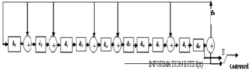
The operation of the Encoder LFSR design of figure 1 is as follows:
1. For the clock cycle 1 to k, the original message bits are transmitted without changing its form (during this operation switch s2 is in position 2), and the linear feedback shift register calculates the parity bits (switch s1 is on now).
2. For cycle k+1 to n, the generated parity bits in the linear feedback shift register are transmitted (switch s2 is in position 1) and the feedback in the LFSR is switch off (s1 off).
A. Design of Encoder for (15, 11, 1) BCH Code
Encoder for (15, 11, 1) single error correcting BCH codeis designed by organizing LFSR with generated polynomial1+x+x4 and implemented on Spartan 3S1000 FPGA ofXilinx. The RTL view and Schematic is generated bysynthesis with Xilinx ISE 14.2.
Figure 2 LFSR block diagram for (15,11,1)BCH encoder
B. Design of Encoder for (15, 7, 2) BCH Code
Encoder for (15, 7, 2) double error correcting BCH code is designed by organizing LFSR with generated polynomial 1+x4+x6+x7+x8 and implemented on Spartan 3S1000 FPGA of Xilinx. The RTL view and Schematic is generated by synthesis with Xilinx ISE 14.2
Figure 3 LFSR block diagram for (15, 7, 2) BCH encoder
C. Design of Encoder for (15, 5, 3) BCH Code
Encoder for (15, 5, 3) triple error correcting BCH code is designed by organizing LFSR with generated polynomial 1+x+x2+x4+x5+x8+x10 and implemented on Spartan 3S1000 FPGA of Xilinx. The RTL view and Schematic is generated by synthesis with Xilinx ISE 14.2,
Figure 4 LFSR Block diagram for (15, 5, 3) BCH encoder
a. Simulation Waveform Result of (15, 11, 1) BCH Encoder
Yathiraj H U
et al
, International Journal of Computer Science and Mobile Applications,
Vol.2 Issue. 5, May- 2014, pg. 45-54 ISSN: 2321-8363
©2014, IJCSMA All Rights Reserved, www.ijcsma.com 49
Figure 5: Simulated Waveform for (15, 11, 1) BCH Encoder
b. Simulation Waveform Result of (15, 7, 2) BCH Encoder
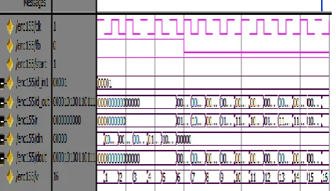
The timing simulation of (15, 7, 2) BCH encoder is shown in Fig. 6. Two data sequence is shown from 580 ns - 880 ns and 880 ns - 1180 ns. Total of 15 clock cycle is taking to complete transmitting of 15 codeword, 7-bits are information bit and 8- bits are parity bit. 7 Information bits “1011001” are transmitting as it is where as other 8 bits “00110100” are transmitting as parity bit “00011110”.
Figure 6. Simulated Waveform for (15, 7, 2) BCH Encoder
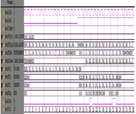
c. Simulation Waveform Result of (15, 5, 3) BCH Encoder
The timing simulation of (15, 5, 3) BCH encoder is shown in Fig. 7. Two data sequence is shown from 640 ns -940 ns and 940 ns - 1240 ns. Total of 15 clock cycle is taking to complete transmitting of 15 codeword, 5-bits are information bit and 10- bits are parity bit. 5 Information bits “00110” are transmitting as it is where as other 10 bits “0110010100” are transmitting as parity bit “010001110”.
Yathiraj H U
et al
, International Journal of Computer Science and Mobile Applications,
Vol.2 Issue. 5, May- 2014, pg. 45-54 ISSN: 2321-8363
©2014, IJCSMA All Rights Reserved, www.ijcsma.com 50
V. DECODER DESIGN
The high level decoder design is shown in the figure.8
Figure 8 BCH Decoder design
a. DECODER DESIGN AND ARCHITECTURE OF (15, K) FOR t=1
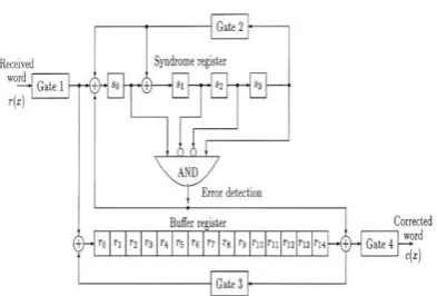
Figure 9 Decoder block diagram for (15, 11, 1) BCH decoder
Figure 9 shows the block diagram of (15, 11) BCH decoder for t=1 single bit error correction. These equations are obtained from the same generated polynomial is given by
g(x) =m1(x) =1+ x + x4
The decoder for the (15, 11) BCH code, based on the Meggitt decoder, with single-error correction will be discussed. Suppose that a single error occurs at xi. When the received word r(x) has completely shifted into the syndrome register, the syndrome in the register corresponds to the error at xi. Now, if we shift r(x) cyclically once in the syndrome and buffer registers at the same time, the error will be at location xi+l and the syndrome contents will be the syndrome corresponding to the error at xi+l.
Yathiraj H U
et al
, International Journal of Computer Science and Mobile Applications,
Vol.2 Issue. 5, May- 2014, pg. 45-54 ISSN: 2321-8363
©2014, IJCSMA All Rights Reserved, www.ijcsma.com 51
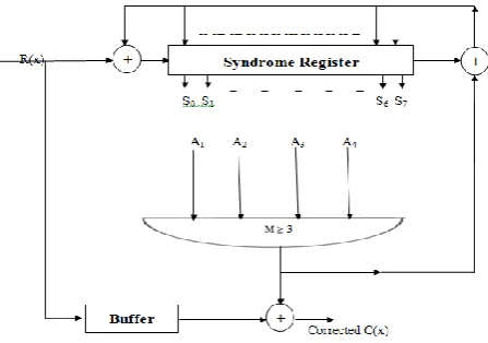
b. DECODER DESIGN AND ARCHITECTURE OF (15, K) FOR t=2Figure 10 Decoder block diagram for (15, 7, 2) BCH decoder
Figure 10 shows the block diagram of (15, 7) BCH decoder for t=2 bit error correction. These equations are obtained from the same generated polynomial is given by, g(x) =LCM{m1(x),m3(x)} = 1+ x4+ x6+ x7+ x8 .
The majority block has the condition of M≥3. Then it finds the error location and corrected it at which error occurred. At error location point it gives the value to the syndrome block for shifting operation in decoder. This decoder block uses the 15 clock cycles in which sending the data into buffer as well as into syndrome block. After giving the code word change, it calculates the majority value and corrects the data. After 15 clocks the corrected code word is available at the corrected data C(x). This decoder module can correct two bits.
C. DECODER DESIGN AND ARCHITECTURE OF (15, K) FOR t=3
Figure 11. Decoder block diagram for (15, 5, 3) BCH decoder
Figure 11. shows the block diagram of (15, 5) BCH decoder for t=3 bit error correction. These equations are obtained from the same generated polynomial is given by
g(x) = LCM{m1(x) * m3(x) * m5(x)} = 1 + x + x 2
+ x4 + x5 + x8 + x10.
Yathiraj H U
et al
, International Journal of Computer Science and Mobile Applications,
Vol.2 Issue. 5, May- 2014, pg. 45-54 ISSN: 2321-8363
©2014, IJCSMA All Rights Reserved, www.ijcsma.com 52
d. Simulation Waveform Result of (15, 11, 1) BCH DecoderFigure 12 output waveform for BCH (15,11,1) decoder
The figure 12 shows the simulation results of BCH (15, 11, 1) decoder. The inputs given to the module are clk, d_in, sr, start
and the output taken from the module are d_out. And din, dout, s, k, l, m, v represent intermediate signals. Clock signal is given to the clk input. The 15 bit received code word is given to d_in input. First give the sr input as 0 and start input as 1, the 15 bit received code word is 111110001100111. After giving the code word change sr input to 1 after 16 clock cycles. After 33 clocks the corrected code word is available at the d_out output. This decoder module can correct only one bit. The corrected code word is 110110001100111.
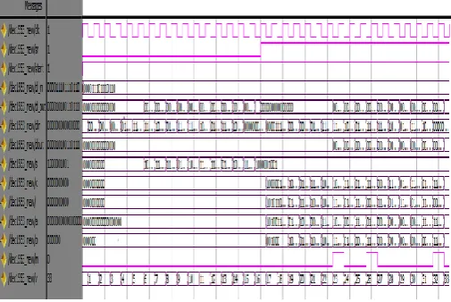
e. Simulation Waveform Result of (15,7,2) BCH Decoder
Yathiraj H U
et al
, International Journal of Computer Science and Mobile Applications,
Vol.2 Issue. 5, May- 2014, pg. 45-54 ISSN: 2321-8363
©2014, IJCSMA All Rights Reserved, www.ijcsma.com 53
The figure 13 shows the simulation results of BCH (15,7,2) decoder. The 15 bit received code word is given to d_in input. First give the sr input as 0 and start input as 1, the 15 bit received code word is 111011111111000. After giving the code word change sr input to 1 after 16 clock cycles. After 33 clocks the corrected code word is available at the d_out output. This decoder module can correct upto two bits. The corrected code word is 110011111011000
.
Figure 14 output waveform for BCH (15,5,3) decoder
The figure 14 shows the simulation results of BCH (15,5,3) decoder. The 15 bit received code word is given to d_in input. First give the sr input as 0 and start input as 1, the 15 bit received code word is 000011101110110. After giving the code word change sr input to 1 after 16 clock cycles. After 33 clocks the corrected code word is available at the d_out output. This decoder module can correct upto three bits. The corrected code word is 000010100110111.
VI. APPLICATIONS OF BCH CODES
BCH codes are used in applications like satellite communications and two-dimensional bar codes.
Storage devices (including tape, Compact Disk, DVD, special disk drives ...etc.)
Wireless or mobile communications (including cellular telephones, microwave links, pager etc.)
Digital television / DVB .
High-speed modems such as ADSL, xDSL, etc.
ACKNOWLEDGMENT
The authors would like to thank our guide assistant professor Mrs. Prameela N S and TIFAC (Technology Information Forecasting and Assessment Council) and Shree Devi college of Engineering, Mangalore for supporting this research.
CONCLUSION
The result presented from the synthesis and timing simulation, shows the (15, 5, 3) BCH Encoder and decoder are more advantageous over the other two, according to speed requirement It can correct 3 error at the receiver side when the original data corrupt by the noise. But when considering area then (15, 11, 1) is better which can correct only 1 bit error. Also redundancy is less and data rate is more in it.
BCH codes have been shown to be excellent error correcting codes among codes of short lengths. They are simple to encoder and relatively simple to decode. Due to these qualities, there is much interest in the exact capabilities of these codes. The speed and device utilization can be improved by adopting parallel approach methods.
REFERENCES
[1] Amit kumar Panda, Shahbaz sarik, Abhishek Awasthi “FPGA Implementation of Encoder for (15, k) Binary BCH Code Using VHDL and Performance Comparison for Multiple Error Correction Control”, International Conference on Communication Systems and Network Technologies © 2012 IEEE DOI10.1109/CSNT.2012.170
Yathiraj H U
et al
, International Journal of Computer Science and Mobile Applications,
Vol.2 Issue. 5, May- 2014, pg. 45-54 ISSN: 2321-8363
©2014, IJCSMA All Rights Reserved, www.ijcsma.com 54
[3] Berlekamp, E.R., Peile, R.E. and Pope, S.P. (1987), "The application of error control to communications", IEEE Communication
[4] Goresky, M. and Klapper, “A.M. Fibonacci and Galois representations of feedback-with-carry shift registers”, IEEE Transactions on Information Theory, Nov 2002, Volume: 48, On page(s): 2826 -283Magazine, 25, no4, pp 40-57.
[5] Bhawna Tiwari and Rajesh Mehra “Design and Implementation of Reed Solomon Decoder for 802.16 Network using FPGA”. 978-1-4673-1318-6/12©2012IEEE.
[6] M.Y. Rhee - "Error Correcting Coding Theory", McGraw-Hill, Singapore, 1989. [7] S. Lin, and D.J. Costello Jr. - "Error Control Coding", Prentice-Hall, New Jersey, 1983. [8] E. R. Berlekamp, "Algebraic coding theory", McGraw-Hill, New York, 1968.
[9] R.E. Blahut, "Theory and practice of error-control codes", Addison-Wesley, Reading, MA, 1983.
[10] S. B. Wicker, “Error Control Systems for Digital Communication and Storage”. Upper Saddle River, New Jersey 075458: Prentice Hall, Inc,1995.
[11] Shu Lin, Daniel J. Castello, "Error control coding, Fundamentals and applications", Premtice-Hall, New Jersey, 1983, Pages 15-50.
[12] Shu Lin, Daniel J. Castello, "Error control coding, Fundamentals and applications", Premtice-Hall, New Jersey, 1983, Page 141-182.