_____________________________________________________________________________________________________
Three Phase Inverting Using Pulse Width
Modulation Controlled by 6802 Motorola
Microprocessor
Atef Almashakbeh
1*1Department of Electrical Engineering, Tafila Technical University, P.O.Box 179, 66110 Tafila, Jordan.
Author’s contribution
The sole author designed, analysed, interpreted and prepared the manuscript.
Article Information
DOI:10.9734/JERR/2019/v7i416977 Editor(s): (1) Dr. David Armando Contreras-Solorio, Professor, Academic Unit of Physics, Autonomous University of Zacatecas, Mexico. Reviewers: (1) Şükrü Kitiş, Dumlupınar Üniversitesi, Turkey. (2)Subramaniam Jahanadan, Labuan Matriculation College, Malaysia. (3)I. B. Ramdhane, Gaston Berger University, Senegal and University of Science, Technology and Medicine, Mauritania. Complete Peer review History:http://www.sdiarticle4.com/review-history/52096
Received 12 August 2019 Accepted 14 October 2019 Published 23 October 2019
ABSTRACT
Different types of voltage sources are available in the market, but the point is how to convert any voltage to our desired waveform? For example; if we have a DC voltage source (like battery or dc generator) and we need to run AC motor (one phase or three phases) or run DC motor with special voltage, or we have an AC source (one phase or three phases) and need to run AC machine with special voltage and special frequency or run DC machine with special voltage. In simple meaning we need a connector between the sources and loads to match between them. But it should pass this conditions; efficiency, mobility, size, weight, range of operation, simple with using and cost. This paper focuses on designing and producing a true sinewave inverter that provides premium power which is identical to (or even better than) the power supplied by the utility company with multi output. On this work we will give an explanation for type of inverter depend on output and function for it.
1. INTRODUCTION
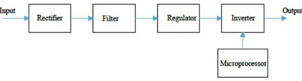
The electric converter system (ECS) contains five major block units and a transformer as viewed in Fig. 1.
Fig. 1. ECS system
And they are:
a) Rectifier circuit; for rectifying the single phase or three phase to (DC) direct current and to union the direction of output current if the input is (DC).
b) Filter; for rippling the output of rectifier, to make it easy for regulating in the next step. c) Regulator; for regulating output to become
pure (DC).
d) Inverter; for convert (DC) to (AC 3ф) and controlling by PWM wave form.
e) Microprocessor; that is the brain of system where it connect with inverter.
2. EXPERIMENTAL SETUP
2.1 Microcontroller
As shown in Fig. 2, we used microprocessor 6802 Motorola that has 16 bit address bus, 8 bit data bus and control bus that separated from each other and it connected with crystal oscillator 2MHz as clock. Data bus goes from microprocessor to quadruple bus transceiver (74LS243) where it used to neglect noise and protected the micro. Then the data bus distribute to the erasable programmable read only memory (EPROM), random access memory (RAM) and parallel interface adapter (PIA).
a. RAM 6810 128 byte. b. EPROM 2732 4096 byte.
c. PIA 6821. Used as interface between microprocessor and peripheral device.
Address bus goes from microprocessor to octal bus buffer (74HCT241) then the address bus distribute to the RAM & EPROM.
We used decoder (74HC138) to enable or disable the peripheral device of the
microprocessor depend on the address bus [1]. In general the program that we design has six control line outputs that controlled the MOSFET.
Fig. 2. The micro, ROM, PIA, RAM and other component of microcontroller
2.2 Inverter Circuit
The six control lines that carry pulse width modulation, where it’s input for power MOSFET to control the inverter to get three phases, 50 HZ,
380 VL-L. By drive MOSFET (TC4427) that used
to step up the control voltage where the Vgs of
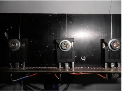
power MOSFET activate at 10V [2,3]. As shown in Fig. 3 we used IRF460LC MOSFET that has:
Drain current 20A. Breakdown voltage 500V. Resistance 0.27Ω.
The average time is between (18 – 77) ns.
In general the inverter consists of six power MOSFET, three drive MOSFET and cooling plats, where the input is DC at 311V and the output is three phases 380VL-L at 50 HZ
Fig. 3. Three powers MOSFET
2.3 Rectifier and Filter Circuit
As shown in Fig. 4 we used S25120 power diode that has:
Forward current 25A. Breakdown voltage 1200V. Resistance 0.025Ω.
Fig. 4. The rectifier and filter circuit
Fig. 5. Picture for all devices connecting together
And we used capacitor as low pass filter where it’s capacity 940µF to minimize the ripple from rectification circuit. In general the rectifier circuit consists of six power diode and two capacitors connected in parallel where the input is single phase 220Vrms at 50 Hz and the output is the input of the inverter [6]. The overall setup is shown in Fig. 5.
3. RESULTS AND DISCUSSION
In this paper, MATLAB software is used to insure that the circuits are correctly operated and compare the outputs of simulation with the practical work.
Fig. 6 shows the simulation electrical circuits for ECS with single phase voltage supply 311Vp
50Hz and connected with induction motor by DC link , in this link we connect abridge rectifier to convert AC input to DC voltage with ripple then we filtered this wave to minimize ripple by low pass filter(parallel capacitor with the rectifier circuit) then to the full bridge inverter that make the AC voltage , controlling by microcontroller that shown in Fig. 6, this controller is the microprocessor 8602 in practical operation that give 36 PWM in the periodic time to get the required amplitude , frequency and phases degree in the simulation of the MATLAB we consider this microprocessor as a pulse generator that give 21 pulse in the periodic time and give us 3 phase 50 Hz as an output of the circuit.
Fig. 6. Simulation circuit
In the Fig. 7, we have 311Vp, 50Hz coming
from the source and rectification to DC as shown in the next steps. The magnitude of the
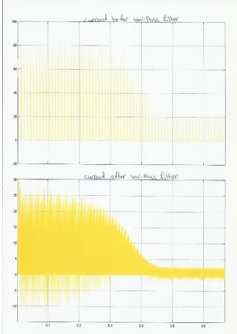
V, when the system go to the steady state the tolerance is (305 to 311) V. The low-pass filter in this circuit is a capacitor 940 µF, which by charge and discharge Contained in capacitor. As we
see; by charge and discharge in capacitor. The magnitude of current will be down from
90.62 A in the transient to steady state consequently in the rectification circuit to 50.12 A after passing the low-pass filter as shown in Fig. 8.
In Fig. 9, the input voltage of the MOSFET about 311V as pulses and current is 4A as pulses this is because of the microcontroller gives the pulse to the MOSFET to be operation and from the data sheet the maximum current and voltage is 20A, 500V Respectively. As shown in In Figs. 10 and 11, this is the line current that output from the DC link between the single phase input voltage and the three output voltage that connected to the load (induction motor [6,7,8])
Fig. 7. (1) Voltage source (single phase). (2) Output voltage from the rectifier. (3) Output voltage after low-pass filter
Fig. 8. (1) Current before low-pass filter (2) current after low-pass filter
Fig. 9. The current pass & voltage applied on the MOSFET
Fig. 11. Line-line voltage Vab, Vbc & 3 phases voltage
Fig. 12. The electrical torque
Fig. 13. The speed of motor Fig. 14. The rotor current & the stator current
the line current is 25A and 3A in transient and steady states, respectively. As
shown we have a good starting for the induction motor, and we have natural
current with magnitude of (-2×10-19)produce by
the harmonic. As shown in the Fig. 12, we see the electric torque on the motor, but we have distortion at the steady-stat that
happened because of the switching the power MOSFET. Not that the electrical torque on the motor depend on the load that effected to the motor (Tm) and as shown in figure the mechanical torque that we applied on motor is zero. The speed of motor is 1490 rpm because the losses, and the rise time very smooth is about 0.44s and its steady state after this time, the overshoot as we see is zero, see Figs. 13 and 14.
4. CONCLUSION
A true sinewave inverter is designed and built to provide premium power, identical to the power supplied by the utility company. The MATLAB software is used in the design and optimization of the system’s components to insure its best performance. The experimental results show that the performance of the built system is the same as those obtained from the MATLAB simulation, emphasizing that the built system operate at its best state, making it a suitable candidate for providing the required power.
COMPETING INTERESTS
REFERENCES
1. Mohan N, Undeland TM, Robbins WP. Power electronics, converters, applications, and design, Second Edition, John Wiley & Sons, Singapore; 1995.
2. Tole Sutikno. Member of IACSIT & IEEE, Mochammad Facta, Member of
IEEE. An efficient strategy to generate high resolution three-phase pulse width modulation signal based on
field programmable gate array.
International Journal of Computer and Electrical Engineering. 2010;2(3):1793-8163.
3. Ned Mohan, Tore M. Undeland, William P. Robbins. Power electronics: Converters, applications, and design. John Wiley & Sons, Inc; 1989.
4. Ismail B, ST. Development of a single
phase SPWM Microcontroller-based
inverter. First International Power and Energy Conference PEC. Putrajaya, Malaysia. 2006;437.
5. Shahriar Muttalib AZM, Ferdous SM, Mortuza Saleque A, Md. M. Chowdhury.
Design and simulation of an inverter with high frequency sinusoidal PWM
switching technique for harmonic reduction in a standalone/ utility grid synchronized photovoltaic system. Informatics, Electronics & Vision (ICIEV). 2012 International Conference. 2012;1168- 1173.
6. Singh GK. A research survey of induction motor operation with non-sinusoidal supply wave forms. Electric Power Systems Research. Elsevier. 2005;75(2–3):200-213. 7. Firdous A, Imran M, Shaik M. Analysis of three phase inverter using different PWM techniques. In Advances in Power
Systems and Energy Management.
Springer, Singapore. 2018;519-530. 8. Bhattacharjee T, Jamil M, Jana A. Design
of SPWM based three phase inverter model. In 2018 Technologies for Smart-City Energy Security and Power (ICSESP) IEEE. 2018;1-6.
© 2019 Almashakbeh; This is an Open Access article distributed under the terms of the Creative Commons Attribution License
(http://creativecommons.org/licenses/by/4.0), which permits unrestricted use, distribution, and reproduction in any medium,
provided the original work is properly cited.
Peer-review history: