Design and Implementation of Automatic GSM Based
Fire Alarm System
Joseph Ilouno
*, Gesa- Felix Newton and Tom-P Fom
Date of publication (dd/mm/yyyy): 17/07/2018
Abstract – Fire accident as an unplanned and undesirable event that brings damages to social wealth and human life needs to be prevented at all cost. In order to prevent losses accrued from fire accidents, various alarm systems have been developed such as smoke detectors, temperature sensor based systems etc. With the advancement of technology more automated fire gadgets are now available among which is this design. The availability of GSM technology is now incorporated into the fire alarm system in order to combat and prevent the menace that could be caused by fire accident. This paper presents the design and implementation of a cost-effective and reliable automated GSM based fire alarm system. The device will be able to monitor the temperature of the environment, the smoke level, send SMS alert to an inbuilt GSM number when necessary, and make loud sound to alert occupants on pending danger. This was achieved by the fabrication of 12 V power supply system that powers the device using step down transformer, programming Arduino Uno Microcontroller using C++ programming Language in the Arduino software platform, and integrating the program med Arduino Uno Microcontroller with GSM SIM900 module.
Keywords – Fire Alarm System, Fire-Detector, GSM Network, Arduino Uno Microcontroller.
I. INTRODUCTION
A fire alarm system is number of devices working together to detect and warn people through visual and audio appliances when smoke, fire, carbon monoxide or other emergencies are present. These alarms may be activated automatically from smoke detectors, heat detectors or may also be activated via manual fire alarm activation devices such as manual call points or pull stations. Alarms can be either motorized bells or wall mountable sounders or horns [1]. They can also be speaker strobes which sound an alarm, followed by a voice evacuation message which warns people inside the building not to use the elevators. Fire and smoke that spread within a building can be affected by various factors such as the geometry, dimension, layout and usage of the building. In order to prevent fire accident in a building, it is critical to detect fire at its early stage and nip it to the bud.
In most instances, fire outbreaks are reported to the fire brigades or authorities very late, often when the entire building has been burnt down. This makes the case for design and implementation of automated fire alarm system a necessity. Automated fire alert system is required not only in industrial complexes but also residential buildings. A fire alarm system is designed to detect the unwanted presence of fire by monitoring environmental changes associated with combustion. In general, fire alarm systems are designed as either automatically actuated or manually actuated [2]. However, some fire alarm systems have been reported to have incorporated both designs in an integrated
manner. Automated fire alarm systems are designed to automatically pick fire signals and notify the building occupants of pending dangers [3].
From history, people have learnt that early response to fire has positive result in controlling fire. When fire is observed, the fire brigade or fire service department is alerted by watchmen using hand bell-ringers or church sextons ringing church bells or factory steam whistle. Unfortunately these methods did not provide accurate details and this often leads the fire department to wrong location. In the 1800s, fire alarms were placed at bell towers around cities to warn off people of fire [1, 2]. Dr. William F. Channing and Moses G. Farmer invented the first fire alarm system in 1852 [1]. The original design was two fire alarm boxes, each containing a telegraphic key with a handle attached. When someone detected a fire, they would crank the handle, which would then relay the details of the fire alarm box number to a central alarm station. The operator at the station would receive the message, which would then be forwarded to the fire department.
In 1890, Francis Robbins Upton designs the first electric fire alarm [1]. This was the first time a thermostat could detect heat and trigger the sprinkler system to displace a fire. This gave birth to fire protection services. As the protection services grew, so did the technology of the fire alarm system. In 1987, Topi Sikanen and Simo Hostikka designed a computational fluid dynamics model for predicting heat release rates of liquid pool fires [2]. Presently, fire detection is recognized to play essential roles in providing fire safety in buildings, protection of lives, and property. The view is in stark contrast to the view of about 50 years ago when automatic detection was rarely installed in buildings. The change in attitude has been as a result of a series of significant fire incidents and research developments. The significant fire that resulted in the loss of numerous lives and involved substantial damage to property and contents and the lack of early detection was identified as a major factor in the outcome of the fire. Today, not only that people are alerted to evacuate a building when there is any fire outbreak but these devices detect fire in its early stage or detect any anticipated fire and warn the occupant about the danger.
In a Conventional fire alarm system, a number of call points and detectors are wired to the Fire Alarm Control Panel in Zones. A zone is a circuit and typically one which wire a circuit per floor or fire compartment. The Fire Alarm Control Panel would have a number of Zone Lamps. The reason for having Zones is to give a rough idea as to where a fire has occurred. The accuracy of knowing where a fire has started is controlled by the number of Zones a Control Panel has, and consequently, the number of circuits that have been wired within the building. The Control Panel would then be wired to a minimum of two sounder circuits which could contain bells, electronic sounders or other audible devices. Sounder Circuits and Detection Zones are wired in a star configuration. Each circuit would have an end of line device which is used for monitoring purposes.
The conventional system is more suited to smaller installations and usually does not contain the processing power or sophistication of the addressable system and hence is usually used in the smaller less complex installation [4]. The detection principle of an addressable system is similar to a conventional system except that the control panel can determine exactly which detector or call point has initiated the alarm. The detection circuit is wired as a loop and up to 99 devices may be connected to each loop. The detectors are essentially conventional detectors, with an address built in. The address in each detector is set by dial switches and the control panel is programmed to display the information required when that particular detector is operated. Additional field devices are available which may be wired to the loop for detection only i.e. it is possible to detect a normally open contact closing such as sprinkler flow switch, or a normally closed contact opening. Sounders are wired in a minimum of two sounder circuits exactly as a conventional system [5].
Analogue fire alarm systems are often known as Intelligent Fire Alarm Systems. There are several types of analogue systems available which are determined by the type of protocol which they use [4, 5]. The control unit decides whether there is a fire, fault, pre alarm or whatever. Essentially, however, analogue systems are far more complex and incorporate far more facilities than conventional or addressable systems [6, 7]. Their primary purpose is to help prevent the occurrence of false alarms.
Wireless fire alarm systems are an effective alternative to traditional wired fire alarm systems for all applications. They utilise licence-free radio communications to interconnect the sensors and devices (smoke detectors, call-points, etc.) with the controllers. It is a simple concept, which provides many unique benefits and is a full analogue addressable fire detection system without the need for cable [8, 9].
II. MATERIALS AND METHOD
Materials
I. LM35 Temperature sensor II. Arduino uno board III. GSM Module (SIM900) IV. LCD display 16x2 V. Buzzer
VI. SIM Card VII.Ferro board VIII. Computer
A.
Review of components used
The Arduino Uno Board:
Arduino is open source hardware board with many open source libraries to interface it on board microcontroller with many other external components like LED, motors, LCD, keypad, Bluetooth module, GSM module etc.
Fig. 1: Arduino Uno Board
GSM Module:
Global System for Mobile communication (GSM) module is a mobile communication modem. GSM is an open and digital cellular technology used for transmitting mobile voice and data services operates at the 850MHz, 900MHz, 1800MHz and 1900MHz frequency bands [10]. The GSM module (SIM 900) is the device responsible for sending SMS if there is any fire outbreak. These modules consist of a GSM module powered by a power supply circuit and communication interfaces (like RS-232, USB 2.0, and others) for computer. A GSM module is a specialized type of modem which accepts a SIM card, and operates over a subscription to a mobile operator, just like a mobile phone.
Fig. 2. GSM Module (SIM900)
LCD Display 16x2:
Fig. 3. 16x2 LCD Display
Smoke Detector:
A smoke detector is a device that senses the presence of smoke in a building and warns the occupants, enabling them to escape a fire before succumbing to smoke inhalation or burns. This type of equipment is used to detect a smoke or other emissions and can interface with a control system so a process can be automatically shut down [12]. A smoke detector can sound an alarm to operators in the area where the leak is occurring.
Fig. 4. Smoke detector (MQ-2)
Temperature Sensor:
LM35 is a precision IC temperature sensor with its output proportional to the temperature (in oC) [13]. The sensor
circuitry is sealed and therefore it is not subjected to oxidation and other processes. With LM35, temperature can be measured more accurately than with a thermistor. It also possesses low self-heating and does not cause more than 0.1
oC temperature rise in still air. The operating temperature
range is from -55°C to 150°C. The output voltage varies by 10mV in response to every oC rise/fall in ambient
temperature, i.e.,its scale factor is 0.01V/ oC. The LM35 is
a low voltage IC which uses approximately +5VDC of power. This is ideal because the arduino's power pin gives out 5V of power. The IC has just 3 pins, 2 for the power supply and one for the analog output.
Fig. 5: LM35 Temperature Sensor
Buzzer:
A buzzer is a mechanical, electromechanical, magnetic, electromagnetic, electro-acoustic or piezoelectric audio signaling device. A piezo-electric buzzer can be driven by an oscillating electronic circuit or other audio signal source. A click, beep or ring can indicate that a button has been pressed. It consists of a number of switches or sensors connected to a control unit that determines if and which button was pushed or a preset time has lapsed. It usually illuminates a light on the appropriate button or control panel, and sounds a warning in the form of a continuous or intermittent buzzing or beeping sound. Initially this device was based on an electromechanical system which was identical to an electric bell without the metal gong (which makes the ringing noise). Often these units were anchored to a wall or ceiling and used the ceiling or wall as a sounding board.
B. Design Circuit
Figure 6 is the circuit diagram of the research work.
B.
Method
Interfacing GSM Module to Arduino Uno Board:
There are two ways of connecting GSM module to Arduino. In any case, the communication between Arduino and GSM module is serial. So it is expected to use serial pins of Arduino (Rx and Tx). Considering this method, the Tx pin of GSM module is connected to Rx pin of Arduino and Rx pin of GSM module to Tx pin of Arduino. Now the ground pin of the Arduino is connected to ground pin of GSM module. So that’s all the connections required to allow communication between the Arduino and the GSM module and the wiring is over. Now one can load different programs to communicate with GSM module and make it work. The problem with this connection is that, while programming, Arduino uses serial ports to load program from the Arduino IDE. If these pins are used in wiring, the program will not be loaded successfully to Arduino. So you have to disconnect wiring in Rx and Tx each time you burn the program to Arduino. Once the program is loaded successfully, you can reconnect these pins and have the system working.
To avoid difficulty, it is preferable to use an alternate method in which two digital pins of Arduino are used for serial communication. TwoPWM enabled pins of Arduino need to be selected for this method. So I choose pins9 and 10 (which are PWM enabled pins). This method is made possible with the Software Serial Library of Arduino. Software Serial is a library of Arduino which enables serial data communication through other digital pins of Arduino. The library replicates hardware functions and handles the task of serial communication.
Interfacing LM35 to the Arduino Board:
LM35 is an analog, linear temperature sensor whose output voltage varies linearly with change in temperature. LM35 is three terminal linear temperature sensors from National semiconductors. It can measure temperature from -55 degree Celsius to +150 degree Celsius. The voltage output of the LM35 increases 10mV per degree Celsius rise in temperature. LM35 can be operated from a 5V supply and the stand by current is less than 60uA. The +5v for LM35 is taken from the +5v out pin of Arduino Uno. Also the ground pin of LM35 is connected to GND pin of Arduino Uno. The Vout (the analog out of LM35) is connected to any of the analog input pin of the Arduino Uno.
Interfacing LCD to Arduino:
The RS pin of the LCD module is connected to digital pin 12 of the Arduino. R/W pin of the LCD is grounded. Enable pin of the LCD module is connected to digital pin 11 of the Arduino. The LCD module and Arduino are interfaced in a 4-bit mode. This means only four of the digital input lines (DB4 to DB7) of the LCD are used. Digital lines DB4, DB5, DB6 and DB7 are interfaced to digital pins 5, 4, 3 and 2 of the Arduino. The 10K potentiometer is used for adjusting the contrast of the display. 560 ohm resistor R1 limits the current through the back light LED. Below is the description of the LCD module pins;
Pin 1 (Vss): Ground pin of the LCD module.
Pin 2 (Vcc): Power to LCD module (+5V supply is given to this pin).
Pin 3 (VEE): Contrast adjustment pin. This is done by connecting the ends of a 10K potentiometer to +5V and ground and then connecting the slider pin to the VEE pin. The voltage at the VEE pin defines the contrast. The normal setting is between 0.4 and 0.9V.
Pin 4 (RS): Register select pin. The JHD162A has two registers namely command register and data register. Logic HIGH at RS pin selects data register and logic LOW at RS pin selects command register. If the RS pin is HIGH and feeds an input to the data lines (DB0 to DB7), it will be treated as data to be displayed on LCD screen. If we make the RS pin LOW and feed an input to the data lines, then this will be treated as a command (a command to be written to LCD controller – like positioning cursor or clear screen or scroll).
Pin 5 (R/W): Read/Write modes. This pin is used for selecting between read and write modes. Logic HIGH at this pin activates read mode and logic LOW at this pin activates write mode.
Pin 6 (E): This pin is meant for enabling the LCD module. A HIGH to LOW signal at this pin will enable the module.
Pin 7 (DB0) to Pin14 (DB7): These are data pins. The commands and data are fed to the LCD module through these pins.
Pin 15 (LED+): Anode of the back light LED. When operated on 5V, a 560 ohm resistor should be connected in series to this pin. In Arduino based projects the back light LED can be powered from the 3.3V source on the Arduino board.
Pin16 (LED-): Cathode of the back light LED.
C.
Fabrication of Power Supply Unit
Materials
I. 12 V Transformer II. NPN diodes
III. 620 µF/25 V capacitors IV. 5 V regulator
contains four diodes D1, D2, D3, and D4. The full wave bridge rectifier is designed to convert an ac sine wave to a full wave pulsating dc signal. The bridge is normally connected to the secondary terminals of the transformer. Current flows from a point with a higher potential to a point of lower potential. During positive half cycle, diode D1 will be reverse biased and will not conduct current while diode D2 will be forward biased and will conduct current. The diode D3 will be forward biased and will conduct current and diode D4 is reverse biased and will not conduct current. During negative half cycle, the diode D1 will be forward biased and will conduct current while diode D2 will be reverse biased and will not conduct current. The diode D3 is reverse biased and will not conduct current but Diode D4 will be forward biased and will conduct current. The output of the rectifier is pulsating dc. This pulsating dc is converted into pure dc using filter. A capacitor is use for the filtration. The value of capacitor depends upon the output voltage and output current. To calculate the value of capacitor the following formulae were used.
Q = C x V (1)
But V = IR
Q = C x IR (2)
Also,
Q = I x T (3)
Substitute equation (3) in equation (1), I x T = C x V
C = (I x T) / V
Here, output voltage is V = 5 DC Output current is I = 300mA
The input voltage is AC 240V, 50 Hz. The output of the transformer is 12VAC, 50 Hz.
So, f = 50 Hz, (for ac) f = 2 x 50Hz =100 Hz (for dc) T = 1/ f
= 1 / 100 Hz T = 0.01s Therefore,
C = (3× 10-3 ×0.01) / 5
C = 0.0006F C = 600 µF
The value of capacitor is 600 µF which is not available in the market, so 620µF was used which is the nearest to 600 µF and is available in the market. The voltage regulator should always be fed as smooth of a dc signal as possible (which gives the best regulated output) so it can regulate it down to its specified voltage. The input voltage has to be larger than the voltage that the regulator regulates out. The voltage entering has to be at least 2 volts higher, so it has to be at least 7 volts. 7 volts would work perfect. The middle Pin of the regulator is ground. Without ground, the circuit couldn't be complete because the voltage wouldn't have electric potential and the circuit wouldn't have a return path. The third pin is the output pin.
Fig. 7. 5V power supply
III. RESULTS
Temperature Sensor Analysis
The sensor used is LM35. The voltage output of the LM35 increases 10 mV per degree celsius rise in temperature. LM35 can be operated from a 5 V power supply and the stand by current is less than 60 µA. To measure temperature using microcontroller, the relationship between temperature and output of LM35 is found. The transfer function of LM35 is given by the relation:
Vout = 10 mV/oC × Temperature
Since the device is programmed to respond at 40oC,
therefore the transfer function of the device will be: Vout = 0.01 × 40 = 0.4V
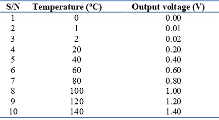
For each degree rise in temperature, there is a rise of 0.01 V in output temperature. For some values of temperature, the output voltage is shown in Table 1.
Table 1: Relationship between temperature and output voltage of LM35
S/N Temperature (oC) Output voltage (V)
1 0 0.00
2 1 0.01
3 2 0.02
4 20 0.20
5 40 0.40
6 60 0.60
7 80 0.80
8 100 1.00
9 120 1.20
10 140 1.40
With the same relationship, the sensor can sense temperature from -55oC to 150oC. In order to determine
temperature from output voltage, value has to be multiplied by 100.
IV. DISCUSSION
ignition sources including any item, action, or process which produces heat. These encompass electric lighting and power systems, heating and air conditioning equipment, heat producing conservation and maintenance activities, and electric office appliance. Flame generating construction activities such as soldering, brazing, and cutting are frequent sources of ignition. Arson is unfortunately one of the most common cultural property ignition sources, and must always be considered in fire safety planning. When the ignition source contacts the fuel, a fire can start. Following this contact, the typical accidental fire begins as a slow growth, smoldering process which may last from a few minutes to several hours. The duration of this "incipient" period is dependent on a variety of factors including fuel type, its physical arrangement, and quantity of available oxygen. During this period heat generation increases, producing light to moderate volumes of smoke. The characteristic smell of smoke is usually the first indication that an incipient fire is underway. It is during this stage that early detection (either human or automatic), followed by a timely response by qualified fire emergency professionals, can control the fire before significant losses occur. As the fire reaches the end of the incipient period, there is usually enough heat generation to permit the onset of visible flames. Once flame appears the fire changes from a relatively minor situation to a serious event with rapid flame and heat growth. Ceiling temperatures can exceed 1,000° C (1,800° F) within the first minutes. These flames can ignite adjacent combustible contents within the room, and immediately endanger the lives of the room's occupants. A key aspect of fire protection is to identify a developing fire emergency in a timely manner, and to alert the building's occupants and fire emergency organizations. This is the role of fire detection and alarm systems. Firstly, they provide a means to identify a developing fire through either manual or automatic methods and second, they alert building occupants to a fire condition and the need to evacuate. Another common function is the transmission of an alarm notification signal to the fire department or other emergency response organization.
V. CONCLUSION
Fire accident claims the lives of innocent people around the world every single day. A small amount of fire is able to damage a huge part of a society. Although smoke detectors and fire alarms alert people of danger, they often have few choices other than escaping from a building and calling the fire department. In this paper, it can be concluded that the proposed system can provide a secure, safe, and efficient way for preventing or combating fire accident. This was achieved by the fabrication of 12 V power supply system that powers the device, programming Arduino Uno Microcontroller using C++ programming Language in the Arduino software platform, and integrating the program med Arduino Uno Microcontroller with GSM SIM900 module. The GSM SIM900 module was incorporated in the system in order to send sms to the occupant of the building on any impeding danger so as to combat the situation on time and to prevent losses.
REFERENCES
[1] L. Zhang and G. Wang, ‘Design and Implementation of Automatic Fire Alarm System based on Wireless Sensor Works’, Proceedings of the International Symposium on Information Processing (ISIP’09), Huangshan, 2009, pp 410-413.
[2] O.H. Kwon, S.M. Cho, and S.M. Hwang, ‘Design and Implementation of Fire Detection System. Advanced Software Engineering and its Applications’, Hainan Island, 2008, pp. 233-236.
[3] J. H. Li, X. H. Zou, and W. Lu, ‘The Design and Implementation of Fire Smoke Detection System Based on FPGA’, Proceedings of the 24th Control and Decision Conference, Taiyuan, 2012, pp 3919-3922.
[4] A. Cote and P. Bugbee, ‘Ionization Smoke Detectors: Principles of Fire Protection’, National Fire Protection Association, Quincy, 249, 1988.
[5] Northeast Document Conservation Center, Nick Artim, an Introduction to Fire Detection, Alarm, and Automatic Fire Sprinklers, Available: http://www.nedcc.org/free- resources/preservation-leaflets/3.-emergency-management/3.2- an-introduction-to-fire-detection,-alarm,-and-automatic-fire-sprinklers
[6] R.W. Bukowski, R.D. Peacock, J.D. Averill, T.G. Cleary, N.P. Bryner, W.D. Walton, P.A. Reneke, and E..D. Kuligowski, ‘Performance of Home Smoke Alarms Analysis of the Response of Several Available Technologies in Residential Fire Settings’, NIST TN 1455-1; NIST Technical Note 1455-1; 2007, pp. 396. [7] J. Gerhart, ‘Home Automation and Wiring’ McGraw-Hill
Professional, 1999, ISBN 0070246742.
[8] H. Richard, ‘Inside the Smart Home’, Springer, 2003, ISBN 1852336889.
[9] T. Nikola, ‘Method of and apparatus for controlling mechanism of moving vessels and vehicles’, United States Patent and Trademark Office, U.S. Patent 613809, 1898.
[10] W.C. Mann, ‘Smart technology for aging, disability and independence : the state of the science’, John Wiley and Sons, 2005, ISBN 0-471-69694-3.
[11] R. Antunes, ‘Intruder alarm systems: the state of the art’, Proceeding of the 2ND International Conference on Electrical
Engineering, 2007, pp. 251-261. ISBN 972-99064-4-2. [12] M. Griffiths, ‘Smart Home Security: Home building &
Renovating’, ABI Research Mobile, 2008.