The Effects of Blade Angle on Blade Stresses During Cutting
of Different Kinds of Paper Materials
Abdullah Kurt1,* - Erdogan Kose2- Turkun Sahinbaskan3
1 Gazi University, Technical Education Faculty, Mechanical Department, Turkey 2 Gazi University, Technical Education Faculty, Printing Department, Turkey 3 Marmara University, Technical Education Faculty, Printing Department, Turkey
In the printing sector knives (blades) are used during pre-printing, printing and post-printing. Therefore, paper type, blade angles, the sharpness of blades and applied pressure are all important factors in terms of cutting quality. In this study, during the cutting of different kinds of paper material, the effects of blade angle on blade stresses has been investigated. Using paper pulp I, paper pulp II, coated paper and Bristol paper various analyses have been made. In the analyses, according to changes to blade angles of 20, 22, 24, 26, 28 and 30°, changes have been observed in maximum principal stress, S1,
minimum principal stress, S3 and von Mises stresses, SEQV. In conclusion; since Von Mises stresses and
especially max. compressive stresses (min. principal stress, S3) occurred at the lowest level for paper pulp
I, paper pulp II, coated paper and Bristol papers, it has been decided that for increased durability of the knife the critical blade angle in terms of abrasion/breakage of the blade should be 28 degrees rather than the more widely used angle of 24°. A blade angle below 22 degrees is not advised.
© 2009 Journal of Mechanical Engineering. All rights reserved.
Keywords: paper, blade, stress, ANSYS
0 INTRODUCTION
Cutting jobs have an important place in the printing industry. All paper products from the smallest label to all types of posters, brochures, magazines, books, newspapers and billboards have to be prepared according to a specific size. For this reason guillotine paper cutters are required both, in pre-printing and post-printing. Guillotine paper cutters are used in the printing sector; to correctly size the paper in accordance with the printing machine that is used to carry out the printing process, to separate any extra copies that have been printed and to cut off any excess from the edges of papers that have been printed and bound. With regards to work quality and customer satisfaction, cutting is a highly delicate matter in the printing industry. All cutting jobs produced under rapidly developing technological conditions must adapt to certain standards of quality. Otherwise, printing houses face the risk of losing their customers.
The most common cutting range of cutting materials used in printing is paper, paperboard and cardboard. Such cutting materials are categorized as soft, normal and hard. Copy paper, tissue paper, drying paper and silk paper are all soft materials. Valuable papers such as printing
paper, cardboard, bond-bill paper are normal cutting materials. Hard cutting materials, however, are materials such as coated paper, chrome paper, paperboard, label paper and adhesion paper. Guillotine paper cutters are of steel and steel alloy. This steel alloy composition determines the life of the blade. The durability of the blade is also closely related to the cutting material used. If blades for soft and normal cutting materials are used on hard cutting materials they will quickly wear out and become blunt. The main reason for this is that hard cutting materials display great resistance during cutting. Blade angles also have an important place in cutting jobs. Blades with small angles require less cutting strength compared to blades with larger angles. Blades with small angles cannot remain strong in hard and flexible cutting materials; they will bend or eventually wear out. For example, a blade with a small angle is not forced with soft and high stowing but it is forced with hard stowing and so it is quickly worn out.
The following knives (blades) are employed [1]:
− Standard steel knives (5% share of alloy),
− HSS-knives (super speed steel knives, 18% tungsten as an alloy share),
− Carbide-tipped knives (75 to 95% tungsten carbide, pressed in a powder metallurgy procedure).
Not only the price of the new knife should be calculated but also the average number of cuts (service life), the resulting knife changes, the price for grinding (per meter) and the average grinding of the blade in millimetres [1].
It is interesting how little work exists in literature relating to printing technology and knives used in cutting processes. Bishop and Wilson [2] discussed the method for both velocity control and deceleration by the use of a single pneumatic cylinder. In addition, a method of reducing velocity variability due to differences among the work functions of the mechanism is described, and the application of such a device to a paper-cutting mechanism is presented. The concepts and theory presented are general and therefore, apply to the entire class of spring-driven mechanisms. The design of the control device was facilitated by the use of a mathematical model. In addition to the active forces, an inertia effect of the stationary knife caused by a “scissor” action of the mechanism was taken into account (the axes of the two knife blades are slightly inclined to insure proper shearing action. As a result, the stationary knife is displaced through a small angle as the rotating knife cuts the paper). A dynamic friction force produced by the associated inertial reaction was taken into account.
The finite element method, by separating complicated problems into simple lower problems, is a method of solution in which the complete solution is found by solving each problem within itself. Since the subject of this study shows similarities to mechanical engineering, especially to the process of machining, it has benefited greatly from the FEM works in this field. There has been an increase in attention given to numeric methods, especially the finite element method, due to the developments in computer technology and complex codes. While the Eulerain formulation is used in one part of the models used for the modelling of orthogonal cutting, the Lagrangian
formulation, which enables chip formation from beginning to steady-state, has been used on a more widely basis. To improve the accuracy and effectiveness of the finite element method, various techniques of this method such as element separation [1] to [6], modelling of cutting tool wear [1], [2] and [4] to [6], re-meshing [5] and friction modelling [1] to [6] have all been applied. Looking at the works related to the finite element method in literature; it is observed that the process of chip formation formed during the cutting process of a large part of the work consists of two dimensional simulation [6] and [9]. For simulation, commercial software such as MARC, ABAQUS, DEFORM 2D/3D, NIKE, DYNE has been used.
In this study, the effects of blade angle on blade stresses during cutting of paper pulp I, paper pulp II, coated paper and Bristol paper has been investigated with the help of the finite element method based ANSYS software. Changes to the maximum principal stress, S1, minimum principal stress, S3 and von Mises stresses (SEQV) formed on blades with different angles have been observed and the required critical blade angle in terms of abrasion/breakage of the blade as a result of cutting each paper type has been investigated.
1 MATERIAL AND METHOD
In this study, in which the effect of cutting different kinds of paper on blade stresses has been investigated, technical properties of the knives used on the POLAR 115 High Speed Cutter workbench (Fig. 1) given in Table 1 have been set as the basis for the investigation. The paper cutting system and knife used is shown in Fig. 2a and b, respectively.
Table 1. Technical properties of the POLAR 115 High Speed Cutter [2]
Cutting width [mm] 1150
Feeding depth [mm] 1150
Feeding height max. (without false clamp) [mm] 165
Front table length [mm] 715
Table height [mm] 900
Safety clamp pressure [daN] 30
Clamp pressure, min [daN] 150
Clamp pressure, max [daN] 4500
Backgauge speed on return way (0 -...) [mm/sec] 300
Knife speed [cycles/min] 45
Knife thickness [mm] 13.8
Knife grinding reserve (HSS 18 knife), max [mm] 50 Smallest cut, manual, w/o false clamp plate [mm] 20 Smallest cut, automatically, w/o false clamp plate [mm] 25 Smallest cut, automatically, with false clamp plate [mm] 95
Noise level [dB/A] 77
Fig. 2. Paper cutting system [2]
1.1 Finite Element Analysis
Blade set stresses for HSS super speed steel knives, 18% tungsten as an alloy share, with an elasticity module of 200 GPa and Poisson ratio of 0.3 are analysed using cutting strength data obtained from the workbench producing company with the help of the finite element based ANSYS 9.0 software. By taking into consideration the geometrical properties of the blade edge, the modelling process of the blade is carried out when the model which is formed in the Mechanical Desktop 6 Power Pack is transferred to ANSYS in “.iges” format.
While an 8 nodal quadrilateral PLANE82 component was chosen for blade edge meshing; a SURF153 component has been used so that blade force is applied in normal and tangential load distributions over the blades main cutting surface and cutting surface accessory. The process of component separation is carried out with the “smartsize” method which automatically adjusts
the most appropriate component order for solid model geometry. Accordingly, the dimensions of network components have been applied as smartsize = 4 for all blade edges. As a boundary condition, displacements in areas where the blade is mounted to the blade guider component were selected zero.
0.1⋅F⋅sin α and SR = 0.1⋅F⋅cos α. In a proper spread out surface load manner, T, SN and SR forces are applied to each component on the main cutting surface and cutting surface accessory.
In addition to the 24° angle used widely in the sector; different models formed with angles of 20, 22, 24, 26, 28 and 30° for each paper type have been used to investigate stresses on the blade angle (α). In the analyses friction between the blade and the paper is ignored and the fact that the blades are sharp (not blunt or used) is observed.
h
α F
T
SN
SR
F
T S
SN
SR
Fig. 3. Load distributions on the blade
2 STRESS DISTRIBUTIONS ON THE BLADE
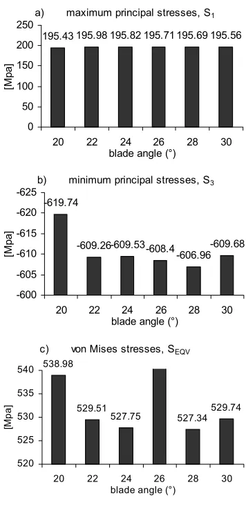
According to the loading situation described above, using different models with angles of 20, 22, 24, 26, 28 and 30° for each paper type; the maximum principal stress (S1), minimum principal stress, (S3) and von Mises stresses (SEQV) formed on the blade have all been investigated. Stresses that are obtained according to changes to the blade angle for each paper type are shown in Figs. 4 to 7.
When investigating maximum principle stresses formed during the cutting of 80 (gsm) Paper pulp I we find that blade angles do not have a great impact on these stresses. While a similar result is obtained with minimum principle stresses, we can also say that stresses have a tendency to increase at angles below 22 degrees. Similarly, stresses have a tendency to rise when von Mises stresses fall, especially below 22 degrees of the angle.
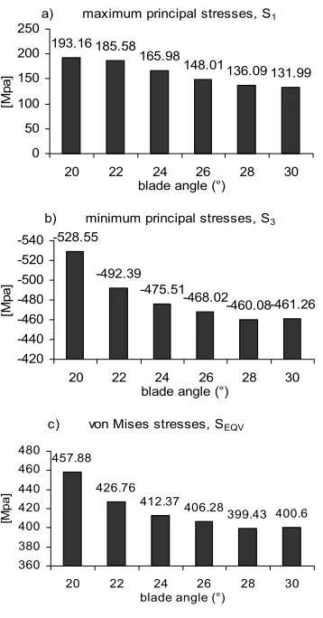
When investigating maximum and minimum principle stresses formed during the cutting of 54 (gsm) paper pulp II we find that stresses decrease as blade angles are increased. In von Mises stresses, there is yet again a decline in stresses as the angle increases and we find that
the maximum increasable angle must remain at 28 degrees.
a) maximum principal stresses, S1
195.98 195.82 195.71 195.69 195.56 195.43
0 50 100 150 200 250
20 22 24 26 28 30
blade angle (°)
[M
pa]
b) minimum principal stresses, S3
-609.26-609.53-608.4-606.96-609.68
-619.74 -625
-620
-615
-610
-605
-600
20 22 24 26 28 30
blade angle (°)
[M
pa]
c) von Mises stresses, SEQV
529.51
527.75 527.34529.74
538.98
520 525 530 535 540
20 22 24 26 28 30
blade angle (°)
[M
pa]
Fig. 4. Effect of blade angle on stresses for (80 gsm) paper pulp I
a) maximum principal stresses, S1
185.58 165.98
148.01 136.09 131.99 193.16 0 50 100 150 200 250
20 22 24 26 28 30
blade angle (°)
[M
pa]
b) minimum principal stresses, S3
-492.39 -475.51 -468.02-460.08-461.26 -528.55 -540 -520 -500 -480 -460 -440 -420
20 22 24 26 28 30
blade angle (°)
[M
pa]
c) von Mises stresses, SEQV
426.76
412.37 406.28399.43 400.6 457.88 360 380 400 420 440 460 480
20 22 24 26 28 30 blade angle (°)
[M
pa]
Fig. 5. Effect of blade angle on stresses for (54 gsm) paper pulp II
When investigating maximum principle stresses formed during the cutting of 230 (gsm) Bristol papers, there was an increase in stresses at 22 degrees, yet it was observed that these stresses declined as the angle increased over 24 degrees.
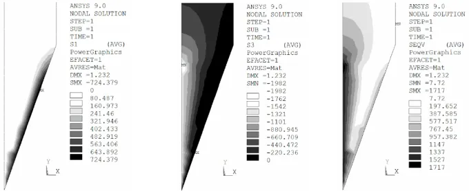
It should be pointed out that here the effectiveness of the paper lies with it being made of hard cardboard. However, stresses declined as the angle increased to 28 degrees in minimum principle stresses. In von Mises stresses as the angle increases there is again a drop. The ideal blade angle here has been specified as 28 degrees. Stress distributions obtained according to blade angle for each paper type are shown in Figs. 8 to 11. Stress distributions for blade angle of the maximum SEQV obtained in the projection of maximum principal stress (S1), minimum principal stress, (S3) and von Mises stress (SEQV) distributions have been used.
a) maximum principal stresses, S1
299.75 264.13 240.03 214.15 198.21 299.99 0 50 100 150 200 250 300 350
20 22 24 26 28 30
blade angle (°)
[M
pa]
b) minimum principal stresses, S3
-770.15 -711.11 -688.7 -674.86-676.91 -783.84 -800 -750 -700 -650 -600
20 22 24 26 28 30
blade angle (°)
[M
pa]
c) von Mises stresses, SEQV
667.29
616.1
579.25 585.33 587.6 678.83 500 550 600 650 700
20 22 24 26 28 30 blade angle (°)
[M
pa]
Fig. 6. Effect of blade angle on stresses for (170 gsm) coated paper
a) maximum principal stresses, S1
727.68 615.32
555.03 510.36 494.96 724.38
0 200 400 600 800
20 22 24 26 28 30
blade angle (°)
[M
pa
]
b) minimum principal stresses, S3
-1808
-1775.3-1755.1-1725.3-1729.7 -1982.1
-2000
-1900
-1800 -1700
-1600
-1500
20 22 24 26 28 30
blade angle (°)
[M
p
a
]
c) von Mises stresses, SEQV
1567.7
1539.3 1523.51497.9 1502.2 1717.1
1350 1450 1550 1650 1750
20 22 24 26 28 30
blade angle (°)
[M
p
a
]
Fig. 7. Effect of blade angle on stresses for (230 gsm) Bristol paper
The composition of Paper pulp I is generally of low density and different tree materials. Its increasable structure in terms of
volume by using cellulose makes it effective here. In the production of paper pulp, primary (long) and secondary (short) fibres are used. Due to the structure of the fibre the blade angle of the blade may not have had an effect on maximum principle stresses during cutting.
It is observed that for 54 (gsm) paper pulp II, 170 (gsm) coated and 230 (gsm) Bristol papers the maximum tension stress distribution is grouped over the section that has been angled near the blade edge. The max. compressive stress (min. principal stress, S3) distribution on the other hand is dispersed towards the guiding point over the blade carrier bar. For von Mises stresses it is collected from under the guiding point and a certain amount is accumulated at the cutting edge. While the production stages of coated paper and Bristol cardboard are similar to that of papers produced directly from cellulose, they show differences due to fibre structure, deinking and flotation chemistry stages. A relationship has been observed between the angle and stresses on these papers which offer thickness in respect of structure and weight in grams. Due to its thick and hard structure it can be said that immediately removing sections that have been cut from the cutting area during cutting using the angle difference helps reduce stresses. Blade abrasion is a matter of high concern in the printing sector which occurs frequently because blades with the same angle are used in the cutting processes of all paper types.
When blades used in the production stage for papers of different compositions are produced with angles according to paper type a sharpening system will be developed.
a) Maximum principal stress, S1 b) Minimum principal stress, S3 c) von Mises stress, SEQV Fig. 9. Stress distributions for (54 gsm) paper pulp II (Blade angle = 20°)
a) Maximum principal stress, S1 b) Minimum principal stress, S3 c) von Mises stress, SEQV Fig. 10. Stress distributions for (170 gsm) coated paper (Blade angle = 20°)
a) Maximum principal stress, S1 b) Minimum principal stress, S3 c) von Mises stress, SEQV Fig. 11. Stress distributions for (230 gsm) Bristol paper (Blade angle = 20°)
Utilization in this sector will then be implemented after taking these changes into account. Therefore, it is observed that blade angles for Bristol cardboards and coated papers are almost equivalent. Different blade angles of
paper pulp I and paper pulp II are also put forward by this study.
of three different blades which operate at different angles should facilitate work in the sector. Paper pulp I are grouped together. It is also possible to evaluate paper pulp II and recycled papers in the same group. Finally, by putting coated paper and cardboard into their own individual groups the three different blade angles in terms of cutting will award the printing sector with extra speed and time.
3 CONCLUSION
In this study the effects of the blade angle on blade stresses during cutting of different kinds of paper materials has been investigated. Various analyses have been made using Paper pulp I, paper pulp II, coated paper and Bristol paper. The analyses show changes in maximum principal stress, (S1), minimum principal stress, (S3) and von Mises stresses (SEQV) on the blade according to blade angles of 20, 22, 24, 26, 28 and 30°.
Paper pulp I (80 gsm): Blade angles do not have a great impact on S1, S3, and SEQV. But S3 and SEQV stresses have a tendency to increase angles below 22 degree. From the stress distributions; S1 stresses are concentrated along the free surface of the blade and are effective all the way up to the sharp edge of the blade while S3 and SEQV stresses reached the highest values around the paper stowing height.
Paper pulp II (54 gsm), coated paper (170 gsm) and Bristol papers (230 gsm): S1, S3, and SEQV stresses decrease as blade angles are increased. But S3 and SEQV stresses have a tendency to increase angles after 28 degree while there is no difference in S1, S3, and SEQV stresses for blade angles of 20 and 22 degrees for coated paper. From the stress distributions, for Paper pulp II, coated paper and Bristol papers; S1 stresses are grouped over the section that has been angled near the blade edge while S3 and SEQV stresses dispersed towards the guiding point over the blade carrier bar.
In conclusion, since Von Mises stresses and especially max. compressive stresses (min. principal stress, S3) occurred at the lowest level for paper pulp I, paper pulp II, coated paper and Bristol paper it has been decided that for increased durability of the knife the critical blade
angle in terms of abrasion/breakage of the blade should be 28 degrees rather than the more widely used angle of 24 degrees. A blade angle below 22 degrees is not advised.
4 REFERENCES
[1] http://www.polar-mohr.com/index_en.html. [2] Bishop, R.E., Wilson, C.C. Dynamic control
of spring-driven mechanisms, IBM Journal of Research and Development, p. 222-230. [3] Strenkowski, J.S., Caroll, J.T. (1985) A
finite element model of orthogonal cutting, ASME, J. Eng. for Industry, 107, p. 349-354. [4] Strenkowski, J.S., Mitchum, G.L. (1987) An improved finite element model of orthogonal cutting, Prod. North American Manufac. Res. Conf., Bethlehem, p. 506-508.
[5] Komvopoulos, K., Erpenbeck, S.A. (1991) Finite element modelling of ortogonal metal cutting, ASME, J. Eng. for Industry, 113, p. 253-267.
[6] Ueda, K., Manabe, K. (1992) Chip formation in micro cutting of an amorphous metal,
Annals of the CIRP, 41, p. 129-132.
[7] Shih, A., Yang, H.T.Y. (1993) Experimental and finite element predictions of residual stresses due to orthogonal metal cutting, Int.
J. for Numerical Methods in Eng., 36, p. 1487-1507.
[8] Shih, A. (1995) Finite element simulation of orthogonal metal cutting, J. Eng. for Industry, 117, p. 84-93.
[9] Zang, B., Bagchi, A. (1994) Finite element simulation of chip formation and comparison with machining experiment, J. Eng. for Industry, 116, p. 289-297.
[10] Usta, M. (1999) Finite element analysis of orthogonal metal cutting operations, PhD Thesis, Middle East Technical University, Graduate School of Natural and Applied Sciences, Ankara.
![Fig. 1. POLAR 115 High Speed Cutter [2]](https://thumb-us.123doks.com/thumbv2/123dok_us/8953161.1862529/2.539.273.464.517.637/fig-polar-high-speed-cutter.webp)
![Table 1. Technical properties of the POLAR 115 High Speed Cutter [2]](https://thumb-us.123doks.com/thumbv2/123dok_us/8953161.1862529/3.539.70.462.65.386/table-technical-properties-polar-high-speed-cutter.webp)