A Software System for “Design for X” Impact
Evaluations in Redesign Processes
Roberto Raffaeli* – Maura Mengoni – Michele Germani Mechanical Department, Polytechnic University of Marche, Italy
Market always asks for new products in short time. It requires an introduction of new tools and methods for managing continuous product changes while evaluating their impact in terms of design efforts, manufacturing costs, time to market, etc in real time. The present research work aims at developing a design platform to support the creation, visualization and navigation of a multilevel product representation where functions, modules, assemblies and components are strictly interrelated. The introduction of “Design for X” principles as rules to relate all aspects contributing to product design, allows evaluating the impact of changes at three levels. The approach and the proposed platform have been applied in the field of refrigerators in order to support both designers and engineers in rapidly configuring the optimal design solution in respect of the company’s requirements formalized by the implemented “Design for X” rules.
©2010 Journal of Mechanical Engineering. All rights reserved.
Keywords: functional analysis and modularity, “Design for X”, change management, impact of design changes
0 INTRODUCTION
Competition in the world markets forces manufacturing companies towards “leanness” of all product development processes, from ideation to manufacturing. An effective lean product design process requires the development of new suitable methods and tools able to guarantee rapidity in evaluating alternative solutions, high flexibility in making product changes, effectiveness in estimating impact in terms of cost, manufacturability, etc.
Generally, the product development process of mass-production goods, like cars and household appliances, can be classified in two main typologies: the ideation of a new product or the evolution of an existing one. Hence, design process can be divided in original design and redesign activities. This last case strongly weights on the time spent in the company design department.
The redesign process of complex products is based on several difficult decision making activities. Introducing new product features as well as modifying existing ones can deeply impact not only on functional aspects, but also in many life cycle aspects that a designer could easily neglect. It refers to production resources, assemblability, product disposal, material reuse, life cycle consumptions, costs, aesthetics,
marketing, etc. From the designer’s point of view, these aspects are often not so clearly linked to the desired product change.
In order to avoid unnecessary iterations, costs and long and unacceptable time to market, it is necessary to enable product developers to understand the influences of changes in all product lifecycle related aspects. By including “design for X” principles already at the beginning of the process, the designer is enabled to take into account different “X contexts” in which his/her actions can indirectly have an impact.
sufficiently wide database of knowledge that enables performance of broad evaluation of design change impacts.
The aim of the present work is to illustrate the cited framework by focusing on product representation and evaluation impact of change for several design perspectives. After a review of the state of the art, the approach is reported in section 2. Afterwards a description of the preliminary software solution is described in order to operatively implement the approach. An experimental test case illustrates an exemplification of the tool application in section 4.
1 STATE OF THE ART
The term “Design for X” (DfX) stands for all the methods, strategies and tools, which enable product developers to consider different important aspects and influences from different product life cycle phases at the same time. DfX is understood as a knowledge system, in which realizations about attaining individual characteristics of technical systems are collected and arranged [2]. The task of product developers exceeds the fulfilment and conversion of function. For the development of technically high-quality and innovative products it is indispensable to consider parameters of systems “X” in early phases of product development (e.g. manufacturing, assembly, recycling, etc.).
By considering aspects regarding DfX at the beginning of the design process, the analysis of different X-systems can be made available to product developers. In order to implement DfX aspects, a methodological support as well as adequate software tools to store and manage information [3] are necessary
The DfX can be successfully adopted during redesign if a product has been thought of according to specific criteria: modular, configurable, adaptable and flexible. The need to improve the efficiency of design processes has led researchers to the definition of formal approaches and methodologies to apply such criteria when modifying existing products. For example the definition of proper modular product architectures can increase design productivity in terms of product variety management [4]. Product architecture is the information about how many components the product consists of, how these
components work together, how they are built and assembled, how they are used, and how they could be disassembled [5] and [6]. Product flexibility, which is conceived as the degree of adaptability to any future change in product design, is strictly correlated to the product’s architecture. In their work Palani Rajan et al. [7] present an empirical study foundation aiming at developing a method to evaluate flexibility of product design and derive a set of guidelines to guide product architecture to a desired state of flexibility.
Product functional structure represents the first step to generate the right product architecture ([8] to [11]); the link between functional domain and architecture domain is represented by functional modules, drawn from the clustering of functions on the basis of energy, material and signal flows [12] and [13]. Since levels of product representation (functions, modules, and components) depend on each other [14], it is necessary to maintain the link among them in order to enable designers to analyse the whole design rationale and the change impact.
If, on the one hand, product architecture is fundamental in order to easily realise the modifications, it is, on the other hand important to early estimate the effects of such modifications. Literature reports many methods to assess the consequences of engineering changes, as reviewed in [15], especially for software-intensive systems in aerospace industry. Basically they can be classified in three groups: traceability, dependency and experiential.
Finally, experiential impact analysis refers to the method using individual or collective understanding and experience to estimate the consequence of changes. It is often applied freely discussing a modification within design teams.
Regarding practice in real industrial context, experiential impact analysis is much diffused. But by facilitating the use of traceability or dependency impact analyses, the company’s capability to manage modifications can be largely improved while unexpected change propagation can be decreased.
With regards to the systems currently available, commercial Product Lifecycle Management software packages allow only circumscribed impact analyses since they do not take into account functional aspects and are unable to predict the extended effects of changes and their implications. In fact PLM modules neglect the product’s functional structure and the way functions are arranged into physical architecture.
In such a context, there are no concrete software tools for management of engineering changes in several life cycle aspects. The aim of this research work is to support the redesign process focusing on knowledge availability to designer to perform his/her choices. Rather than assessing change impact on the basis of probabilistic components relations, the focus is set on the integration of a dependency change management engine in a multilevel product structure and including a more extend knowledge intensive definition of product parts linkages.
2 APPROACH
The proposed methodology and the related software tool enable designers to get an estimation of the engineering change impact taking into account different aspects of product life cycle. Implications of the redesign activities are assessed for each design context through a quantitative evaluation of change impact indices and design activities.
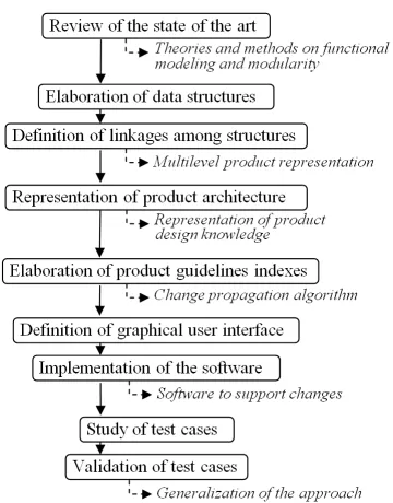
In this section, the research approach is outlined describing the phases of the work that have led to the definition, implementation and testing of a supporting system.
As the first step, a review of the state of the art on product functional modelling, functional basis, modularization and product
architecture representation led to the selection and elaboration of the best suited methodologies. In the previous section, some of them are described.
Fig. 1. Stages and outcomes of the research approach
Secondly, data structures to represent functions, flows, modules, product’s physical components and assemblies have been conceived and reworked in order to permit both graphical representations and elaboration through standard and dedicated algorithms. Three levels, namely functional structure, modular structure and product architecture, represent the main layers of a multilevel framework in which graph networks are used as a means through which changes can spread [18]. The functional structure domain firstly generates a representation according to the ontology of functional concepts. Subsequently, the modular analysis generates the product modular configuration starting from the most detailed level of the functional structure. Then, the product architecture domain proposes how these modules and their functions can be implemented.
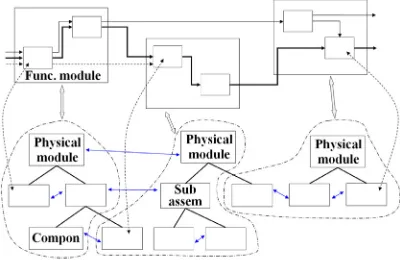
components while moving upwards the design intent is elicited in terms of parts functions and product requirements. The link between the first level and the second one, i.e. the modular configuration, is basically a content-container relationship. On the contrary, the step from the second level to product architecture is more complex. The linkages have been found in Pahl and Beitz [19] solution principles, which give concrete form to a function. Parts, in particular components or assemblies, are mapped to modules on the basis of the functions they implement. In an ideal modular structure, functional modules are perfectly overlapped to physical modules. Normally, as Fig. 2 shows, also for believed modular structures this is not completely true. Parts that refer to the same functional modules may belong to different product assemblies.
Fig. 2. Linkage between modular structure and architecture; physical structure arrangement is mapped to functional structure because they do not show perfect correspondence for believed
modular products either
The central part of the research focuses on the definition of a way to represent product structure in terms of properties and relations in order to capture design knowledge. Several product design guidelines have been selected and indexes defined to capture the influence of components on each of them as described below. The list of “X” contexts is not fixed and can be arranged by an industrial user on the basis of the specific product under development. An example of possible “X” processes can be found in [1].
A change propagation algorithm has been developed to traverse the properties graph giving an estimation of the impact of modification on
several defined design contexts. The work continued with the definition of a suitable software graphical user interface and the implementation of the system. Efforts have been focused on usability in order to minimise data input complexity and knowledge maintenance.
The validation of the method and the system was carried out on a fridge test that was studied and represented in the software system. Modification scenarios were used to assess the quality of the result in terms of correspondence to the actual design activities, correctness of decisions and time savings.
2.1 Approach to Product Architecture Representation
Products are represented by a data structure based on trees and graphs. A component tree, whose nodes are the assemblies, sub-assemblies down to all significant components, represents the product architecture. Screws, bolts, fixtures, wirings can be neglected and their functions represented by a sub-set of the relations between parts. The choice is left to the user on the basis of its experience. Each block, i.e. each tree node, is defined by a name, some properties, an image and implements some functions out of the functional level and links to some documentation files.
environment, cost, production, noise, vibrations and the like.
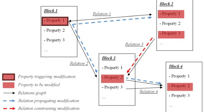
Fig. 3. Product structure representation in terms of properties and relations
Relation is the connection between a property on one hand and one or more properties on the other. In this way, it is possible to manage
one to many connections such as dimensioning formulas. Relations capture both design choices and constrains between product parts.
Each block can be included in the structure with multiple variants definition. This supports the common situation of different alternatives for parts such as motors, actuators, sensors and
modules that are selected on the basis of the needed requirements.
2.2 Assessing the Change Impact
Product change processes can be various. For instance, a component parameter can be changed as a consequence of a new product specification. In this case, the modification is bound to the specific part and its interfaces are maintained constant. On the other hand, other changes can originate from product functional structure [20] and [21]. For example, some sub-functions are removed or new requirements lead to additional new modules.
The proposed change propagation analysis starts from a property which is to be updated. The aim is to browse the structure in order to find all the properties which are connected to the modified property. The propagation algorithm comes out with the list of the components and assemblies to be redesigned and the properties affected.
Relation directionality has been introduced in the data structure and it can be either mono-directional or bi-mono-directional. In the first case, a certain property variation will cause a change to the connected property. For instance, motor rotational speed depends on the frequency of the electricity supplied and not vice versa.
In the second case, properties are symmetrically linked. For instance, an increase of flow rate in a pipe leads to a bigger diameter at constant fluid speed and an increase of pipe dimension will allow more fluid to be transported.
Property and relations graph is traversed according to the following rules:
- modification is iteratively spread from a property to another through relations;
- only relations of selected categories may be considered;
- direction of propagation is evaluated towards relation directionality.
When a relation is traversed coherently to its own directionality, the next property needs to be updated as a consequence of a change in the previous one. On the contrary, this is not correct in the opposite case: the property changing needs to be assessed towards the next property in order to verify the change compatibility (see relation 3 in Fig. 4) which means that the relation constraints the modification. If the modification is compatible with the constraining property the propagation does not spread further. Otherwise, the algorithm needs to also go through the modification of the constraining property. In these cases, the designer can make some considerations and neglect unnecessary branches of propagation.
The above-described method requires a definition of suitable impact indices in order to compute an estimation of the consequences of the modifications for each product life cycle context. Design guidelines are listed in a database and can
easily be added or removed by the user. As mentioned above, separate impact indices are input for each design context. In a formal way the total impact for each context can be assessed as:
b p
Ip
I ,
(1)
where:
• I is the total impact of the modification. For instance, it can express the environmental cost or the assemblability after the modification; • Ip is the impact of the property p of the block
b;
• b is the index of the block and p the index of the property.
In the test case section some examples of computation of Ip indices are presented.
3 “DESIGN FOR X” SUPPORTING SYSTEM
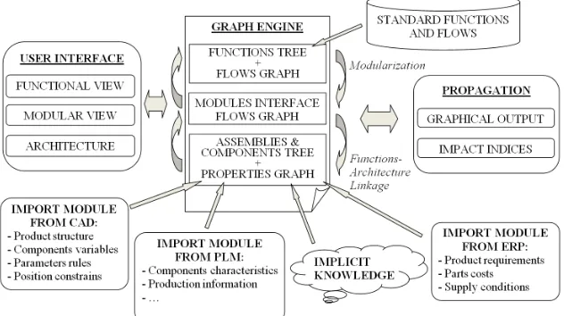
The approach described in the previous section is currently under implementation into a software system. The system’s structure is quite complex and organized in software modules as shown in Fig. 5.
Four main parts can be recognized in the system:
• the core data structures and relative algorithms that store the information on product functional structure, modular structure and product architecture;
• a user interface to input and visualize product views for each level of abstraction;
• data import modules from other company’s IT systems, such as CAD, ERP (Enterprise Resource Planning), PLM, etc.;
• an output module to graphically visualize the outputs of the propagation analysis and compute impact indices.
Graph engine is the system’s core, since it stores product data. The implementation has followed the approach outlined in the second section. The first level, product functional decomposition, is represented by multiple sub-levels of detail, starting from a “black box” model. For each sub-level of detail – usually three on the basis of the common experience of not introducing outlooks on implementing principles – sub functions are connected by flows of material, energy and signal. Well-known functional base vocabulary [10] is employed.
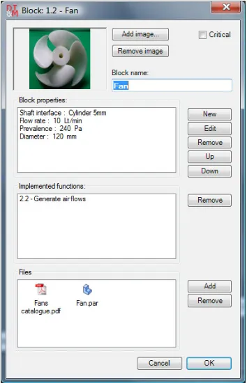
Fig. 6. An example of form used to input data for a block
The second main level is a modular structure, which is drawn from the last sub-level of the functional analysis. Finally, the third level represents the physical structure through a blocks tree. Fig. 6 shows the graphical form to input data for a block. First of all, a name and an image are
associated with the block. Then some lists are defined: design properties, implemented functions and linked files such as CAD models, spreadsheets or text data. Fig. 7 shows what a property definition window looks like. On the right side the available design contexts are listed and the user can associate an impact index when changing the considered property. The list of the DfX processes is previously defined by the user on the basis of the company’s interest. Finally, properties are connected by relations.
Fig. 7. Form to input data for a property; DfX impact indices are listed on the right
The system’s main graphical user interface is shown in Fig. 8. The main part of the interface is made of a tabbed area on the right hand side in which the user can alternate the three different views of the product. In this area, nodes and linkages are respectively represented by rectangles and lines.
Fig. 8. Software main user interface: the functional level; material, energy and signal flows are respectively represented by black, blue and dotted green arrows
3.1 Propagation Output Module
The propagation output module aims to give the designer some feedback on the impact of the introduction of a modification into the product. The algorithm outlined in section 2 has been implemented. Standard graphs analysis techniques have been used to traverse the data structures computing impact indices, node grades, counting elements and lengths of paths.
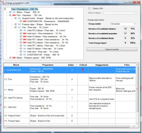
In Fig. 10, an example of possible output is presented for the impact of a single modified
block property. Basically, the system comes out with a composite output made of:
• A tree representing how modification spreads into architecture properties. The root node is the property originating the change. Then, each node of the tree represents a relation that is traversed. A coloured arrow illustrates crossing directionality: red for a constraining relation and blue for the relation propagating the modification. The user can exclude branches of the tree through a check box in order to eliminate meaningfulness propagation paths.
• A table reporting the list of the blocks and the properties to be updated. For each block, the impact index for a selected design context is computed. Moreover, suggestions and links to documentation files are sorted from the input data;
• Impact indices are computed and showed in a separate section in order to have a global measurement of the redesign work. They aim to provide a global impact measurement in order to assess and choose different design solutions. In particular, the total impact expressed as the sum of modified properties indices can be computed for each aspect of product life cycle;
• A graphical output of the impact of modification in the product structure is also available. The portion of relation graphs and blocks is highlighted in order to show the propagation path.
4 TEST CASE
The proposed approach has been applied in the study of a family of refrigerators in order to
come out with new product variants. The research has been carried out in collaboration with Indesit Company Spa, Italian leader in household appliances. In particular, the method was applied in the redesign activity of a combined model made of separate fridge and freezer compartments. The aim of the study is to assess the impact of the introduction of additional specification or the introduction of new parts.
The work moved from a functional and modular analysis of the product. Stone heuristics [13] were used to gather functions in 25 modules [20]. Fridge architecture structure in terms of component and assemblies were retrieved from production Bill of Material. Such BOM is oriented on production and assembly process and product is arranged in 11 physical modules that were mapped to functional modules.
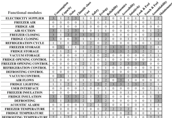
The fridge was analysed in collaboration with the company’s designer and 15 life cycle aspects emerged. Weights were provided for each of the 25 functional modules identified for the specific product (see Fig. 9). Indices were automatically attributed by the system to the blocks and then to the properties.
Fig. 9 shows the results of the analysis. Weights were assigned choosing from 4 values: 0: No importance,
1: Minimum importance, 2: Medium importance, 3: Maximum importance.
The effectiveness of the system was tested on a limited portion of the product bound to the generation and distribution of cold air to the fridge and the freezer compartments. Air is pushed by a fan into the evaporator and then to the storage compartment through some ducts.
Fan performance in terms of prevalence and flow rate depends on its blade geometry and its diameter. A change of the fan model and fluid dynamical properties can make it necessary to review many aspects concerned with heat removal and design of parts managing air circulation. Fig. 10 shows how modification to fan propagates to adjacent parts, such as air ducts and evaporator.
It is important to understand potential impacts on important fridge requirements such as the “climatic class”, the “capacity” or the “consumptions”. The propagation paths are used by the system to compute the impacts on these aspects. For example, the impact on consumption is shown in the table in the lower part of Fig. 10. Changes in the evaporator can have a big impact on consumption since it highly influences the refrigeration cycle. Also, changes on motor and fan are sources of significant consumptions variations, due to their intrinsic efficiency.
5 DISCUSSION OF RESULTS
At the moment, the proposed system is still under development and has been tested only on household appliances (fridge, washing machines, etc.). The tests have shown positive results for this kind of medium complex product category. The generalization of the approach to other fields is under investigation.
The preliminary results have shown that the tool can be mainly employed both by product designers and project managers. The first find it useful as a means of storing information, knowledge and design resource. Moreover, the system provides a check list of the design activities to be accomplished once a certain change has been chosen. On the other hand, project managers regard the approach as a
decision making supporting system that helps to select the best engineering change without having to dive into deep technical details. As product complexity increases, it becomes difficult to input the necessary product knowledge in the system and above all to maintain it. In this case, activities are carried out by specialists in specific design fields and the proposed tool is more conveniently used by managers. Conversely, in small sized design departments the necessity to manage product knowledge is more perceived.
6 CONCLUSIONS
This paper has described an approach in order to support change management process in different design aspects of product life cycle. In particular, the main effort was put on the development of a method and a concrete tool dedicated to the evaluation of design alternatives when carrying out an engineering change.
The ongoing research work has revealed many points that need further investigation. First of all, a more detailed definition of product change factors, obtained thanks to verification through an extended number of case studies, is necessary. A generalization of the approach needs to be further investigated. Then, the software usability needs to be improved in order to facilitate data input. Software modules to retrieve information from the other company’s IT system and a database of more recurrent components can be useful for this purpose.
Finally, to extend the approach in more significant product innovation activities, it is necessary to identify approaches to cope with modifications originating at functional and modular level. Here, functionalities to support functional analysis and modularization are desirable.
7 REFERENCES
[1] Lindemann, U. (2007). A vision to overcome “chaotic” design for X processes in early phases. Proceedings of the 16th International
Conference on Engineering Design, Paris, vol. 1, p. 231-232.
Computers & Industrial Engineering, vol. 41, no. 3, p. 241-260.
[3] Krehmer, H., Eckstein, R., Lauer, W., Roelofsen, J., Stöber, C., Troll, A., Weber, N., Zapf, J. (2009). Coping with multidisciplinary product development – A process model approach. Proceedings of the 17th International Conference on Engineering
Design, Stanford, vol. 1, p. 241-252.
[4] Eppinger, S.D., Chitkara, A.R. (2006). The new practice of global product development,
MIT Sloan Management Review, vol. 47, no. 4, p. 22-30.
[5] Fixson, S.K. (2005). Product architecture assessment: a tool to link product, process, and supply chain design decisions. Journal of Operations Management, vol. 23, p. 345-369. [6] Van Wie, M.J., Rajan, P., Campbell, M.I.,
Stone, R.B., Wood, K.L. (2003). Representing product architecture;
Proceedings of ASME Design Engineering Technical Conferences, Chicago, p. 731-746. [7] Palani Rajan, P.K., Van Wie, M., Campbell,
M., Otto, K., Wood, K. (2003). Design for flexibility – measures and guidelines.
Proceedings of 16th International Conference
on Engineering Design, ICED Stockholm, p. 19-21.
[8] Chakrabarti, A., Bligh, T.P. (2001). A scheme for functional reasoning in conceptual design. Design Studies, vol. 22, p. 493-517.
[9] Otto, K., Wood, K. (2005). Product design: techniques in reverse engineering, systematic design and new product development, Prentice-Hall, New York.
[10] Hirtz, J., Stone, R., McAdams, D., Szykman, S., Wood, K. (2002). A functional basis for engineering design: reconciling and evolving previous efforts. Research in Engineering Design, vol. 13, no. 2, p. 65-82.
[11] Szykman, S., Racz, J., Sriram, R. (1999). The representation of function in computer-based design. Proceedings of the ASME Design Theory and Methodology Conference, Las Vegas.
[12] Höltta, K.M.M., Salonen, M.P. (2003). Comparing three different modularity
methods. Proceedings of DETC ASME
Design Engineering Technical Conferences
and Computers and Information in Engineering Conference, Chicago, p. 533-541.
[13] Stone, R., Wood, K., Crawford, R. (1998). A heuristic method to identify modules from a functional description of a product.
Proceedings of ASME Design Engineering Technical Conference, Atlanta, paper 5642. [14] Zadnik, Ž., Karakašić, M., Kljajin, M.,
Duhovnik, J. (2009). Function and functionality in the conceptual design process. Strojniški vestnik - Journal of Mechanical Engineering, vol. 55, no. 7-8, p. 455-471.
[15] Kilpinen, M., Eckert, C., Clarkson, P.J. (2009). Assessing impact analysis practice to improve change management capability.
Proceedings of the 17th International
Conference on Engineering Design, Stanford, vol. 1, p. 205-216.
[16] Eger, T., Eckert, C.M., Clarkson, P.J. (2007). Engineering change analysis during ongoing product development. Proceedings of 16th
International Conference on Engineering Design, ICED, Paris.
[17] Koh, E.C.Y, Clarkson, P.J. (2009). A
modelling method to manage change propagation. Proceedings of the 17th
International Conference on Engineering Design, Stanford, vol. 1, p. 253-264.
[18] Germani, M., Mengoni, M., Raffaeli, R. (2007). Multi-level representation for supporting the conceptual design phase of modular products. In: Krause, F.L. (ed.), The future of product development, Berlin, p. 209-224.
[19] Pahl, G., Beitz, W. (1988). Engineering Design. A systematic approach, The Design Council, Springer-Verlag, London.
[20] Germani, M., Graziosi, S., Mengoni, M., Raffaeli, R. (2009). Approach for managing lean product design. Proceedings of the 17th
International Conference on Engineering Design, Stanford, vol. 1, p. 73-84.
[21] Wyatt, D.F, Eckert, C.M., Clarkson, P.J. (2009). Design of product architectures in incrementally developed complex products.
Proceedings of the 17th International