Open Access
Research
Estimation of current density distribution under electrodes for
external defibrillation
Vessela Tz Krasteva* and Sava P Papazov
Address: Center for Biomedical Engineering, Bulgarian Academy of Sciences, Acad. G. Bonchev str. block 105 Sofia 1113, Bulgaria
Email: Vessela Tz Krasteva* - [email protected]; Sava P Papazov - [email protected] * Corresponding author
Abstract
Background: Transthoracic defibrillation is the most common life-saving technique for the restoration of the heart rhythm of cardiac arrest victims. The procedure requires adequate application of large electrodes on the patient chest, to ensure low-resistance electrical contact. The current density distribution under the electrodes is non-uniform, leading to muscle contraction and pain, or risks of burning. The recent introduction of automatic external defibrillators and even wearable defibrillators, presents new demanding requirements for the structure of electrodes.
Method and Results: Using the pseudo-elliptic differential equation of Laplace type with appropriate boundary conditions and applying finite element method modeling, electrodes of various shapes and structure were studied. The non-uniformity of the current density distribution was shown to be moderately improved by adding a low resistivity layer between the metal and tissue and by a ring around the electrode perimeter. The inclusion of openings in long-term wearable electrodes additionally disturbs the current density profile. However, a number of small-size perforations may result in acceptable current density distribution.
Conclusion: The current density distribution non-uniformity of circular electrodes is about 30% less than that of square-shaped electrodes. The use of an interface layer of intermediate resistivity, comparable to that of the underlying tissues, and a high-resistivity perimeter ring, can further improve the distribution. The inclusion of skin aeration openings disturbs the current paths, but an appropriate selection of number and size provides a reasonable compromise.
Background
Defibrillation of the heart is widespread and well-estab-lished procedure for resuscitation of cardiac arrest victims [1]. The most accessible approach for electrical cardiac therapy is via external electrodes, placed on selected loca-tions on the surface of the thorax. The electrodes have large contact area (70–120 cm2) [2] and provide high and
supposedly uniform current density distribution in the heart, needed for excitation of most myocardial cells, thus forcing them to return to normal rhythm. Many authors have investigated optimal electrode positions and sizes
via two-dimensional (2D) [3,4] and three-dimensional (3D) [5–7] finite-element method (FEM) models, with the aim of obtaining uniform current distribution in the heart. The uniformity is evaluated by the ratio of the max-imum current (which could result in myocardial damage) and the threshold current needed for defibrillation. For example Camacho et al. [5] found values of 2 to 4.7 for the anterior electrode position. Panescu et al. [6] reported that about 25% of the myocardium volume could be sub-jected to current densities more than 4 times higher than the threshold density.
Published: 16 December 2002
BioMedical Engineering OnLine 2002, 1:7
Received: 4 October 2002 Accepted: 16 December 2002
This article is available from: http://www.biomedical-engineering-online.com/content/1/1/7
BioMedical Engineering OnLine 2002, 1 http://www.biomedical-engineering-online.com/content/1/1/7
Another aspect of the problem is the predominance of high current density along the perimeter of large size trodes applied on human skin. In defibrillation and elec-trosurgery it can lead to unwanted damage and even severe skin burns [8–12] or electroporation [13], under the electrode perimeter area. In transthoracic pacing, it re-sults in strong excitation of sensory nerve endings and provokes skeletal muscle contractions and pain [14,15].
To reduce these adverse effects, Wiley and Webster [8] sug-gested concentric segmented electrodes with higher resist-ance in the periphery, by the use of external resistors adjusted to equalise the currents in the separate segments. A similar approach has been considered in more detail by Kim and co-workers [14]. They have proposed covering the electrode metal with resistive gel of increasing resistiv-ity toward the periphery, according to a specific relation with respect to the electrode radius. An implementation following such a design was tested on patients undergoing atrial cardioversion [16]. The skin damage after defibrilla-tion was assessed by skin biopsy in selected points under the electrodes. The results showed less damage with the use of the modified electrodes compared to the standard ones. However, the authors noted that after separation of the cases where high energies and currents were applied, no difference was found in the skin damage data. This re-sult was not explained. It might be due to breakdown of the higher resistivity electrode layer, or to the overall in-crease of the current density. Also, the skin resistivity and reaction to increased current density and temperature may very probably be nonlinear.
Another problem is related to skin irritation, resulting from long-term application of the electrodes, when a pro-tective wearable defibrillator-monitor is used [17]. In such cases certain specific electrode designs were developed, providing openings for improvement of skin aeration or "breathing" [18].
The aim of the present work is to assess the current density distribution under electrodes of different structure, in-cluding shape, size, interfacing layer thickness and specific conductivity.
Method
The problem can be reduced to the solution of the pseu-do-elliptic differential equation of Laplace type, provided the effects of quasi-stationarity are neglected.
The solution can be obtained for the scalar electrical po-tential V in an electrically conductive domain consisting
of layers of different specific resistivity ρ. The equation is solved subject to the following boundary conditions:
- Dirichlet boundary conditions imposed on the surface SEi in contact with the ith electrode at potential Vi:
- Neumann boundary conditions state that the normal component of the derivative of the potential is zero in the remaining boundary plane (SB), not in contact with the electrodes:
The current density distribution is defined by the poten-tial gradient and the specific conductivity σ of the differ-ent regions:
J(x,y,z) = σ (-gradV(x,y,z)), (4)
here .
In this case, the propagation of the low frequency electro-magnetic field is virtually free of the feedback action from eddy currents, as the human tissue is weakly conductive. Therefore, the skin effect can be neglected.
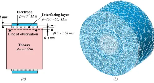
In this study, the finite element method (FEM) was used to estimate the current density distribution in a partially homogeneous conductive medium. It consists of homo-geneous layers (Fig. 1a), simulating the electrode metal, the electrode-skin interface and part of a human body. All structures are modeled as purely resistive, as it has been shown that in defibrillation there was no phase difference between applied voltage and current passed through the thorax [19,20].
Using software for FEM modelling and 3D-computer graphics (parts of ANSYS 5.7 and MATLAB 5.2), a simpli-fied 3D finite element model with over 50,000 eight-node tetrahedron elements was developed (Fig. 1b). Since the measurements were taken 0.5 mm under the electrode-skin interface, the geometry of the thorax was simplified and simulated as a cylindrical domain (10 cm radius; 10 cm height), with specific resistivity 20 Ωm. This value was chosen as an approximate average of very high and very low conductivities (soft tissue, blood and bone, lung air). The estimated inter-electrode resistance R ≈ρl/S ≈ 65Ω (l
∂ ∂ ∂ ∂ + ∂∂ ∂ ∂ + ∂∂ ∂ ∂ =
( )
x V x y V y z V z(1 ) (1 ) (1 ) 0. 1
ρ ρ ρ
V x y z SE Vi
i
, , .
(
)
=( )
2(∂
(
, ,)
) .∂ =
( )
V x y z
n SB 0 3
corresponds to the real conditions in defibrillation. The electrodes, of about 80 cm2 area and 1 mm thickness,
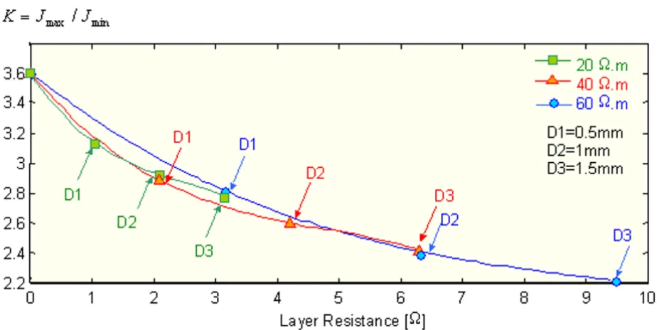
were located on the surface of the upper and lower cylin-der bases. The defibrillation voltage was applied on the group of nodes forming the exterior electrode surface. The inter-electrode potential difference used in all compara-tive studies was set at 1000 V. This value was selected for convenience, since the relative distribution is independ-ent of the voltage applied. The interfacing gel was simulat-ed by a thick (0.5 – 1.5 mm) low-resistivity (20 – 60 Ωm) layer under the electrodes. Thus a varying layer resistance was represented, in a range of 1.5% to 15% of the total thoracic resistance, i.e. value from 1 to 10 Ω.
Results
Standard electrode configurations
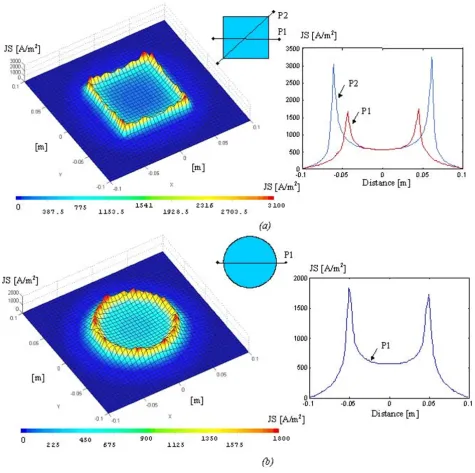
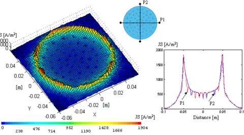
The results of the current distribution simulation, ob-tained for a plane at 0.5 mm under the most commonly used electrode types – rectangular or square-shaped and circular, is presented in Fig. 2a and 2b respectively. The current density profiles along selected axes are shown at the right side. The interfacing layer, of equal surface with the electrode, was chosen of 20 Ωm specific resistivity and 0.5 mm thickness. Thus the total interface resistance un-der both electrodes did not exceed 2.5 Ω. The
square-shaped (8.86 cm side) and circular (5 cm radius) elec-trodes were of equal 80 cm2 area.
Circular electrode analysis
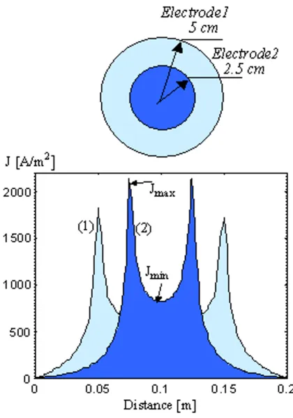
Circular electrodes of different sizes were compared. Two types of electrodes were designed: one of 5 cm and anoth-er of 2.5 cm radius. The respective current density distri-butions are shown in Fig. 3. The interfacing layer resistivity in both configurations was varied to obtain equal non-uniformity, assessed by the so called "non-uni-formity coefficient". The latter was chosen as the ratio (K) of the maximum to the minimum current density: K=Jmax/Jmin. The respective results are presented in Table 1.
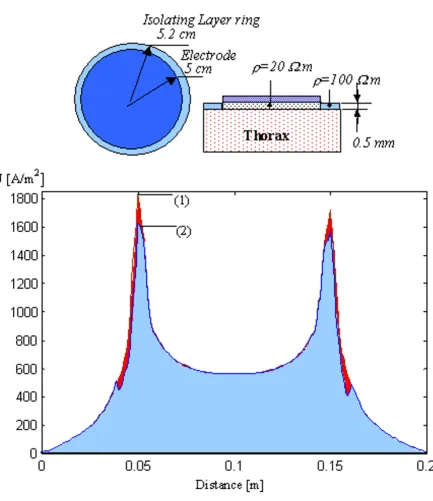
In an attempt to obtain more uniform current distribu-tion, a ring (2 mm width) of higher specific resistivity (ρ = 100 Ωm) was added to the interface perimeter, with a thin isolating barrier between the layer under the elec-trode and the ring (Fig. 4). Thus the peak current density decreased from 1780 A/m2 (1 – without ring) to 1570 A/
m2 (2 – with ring).
The influence of the interfacing layer thickness and specif-ic resistivity ρ was examined by using an electrode of
con-Figure 1
BioMedical Engineering OnLine 2002, 1 http://www.biomedical-engineering-online.com/content/1/1/7
Figure 2
Figure 3
BioMedical Engineering OnLine 2002, 1 http://www.biomedical-engineering-online.com/content/1/1/7
Figure 4
stant radius (5 cm) and variable gel characteristics. Nine simulations were performed: three for ρ = 20 Ωm (inter-face thickness 0.5, 1.0 and 1.5 mm), and three each for ρ = 40 Ωm and ρ = 60 Ωm, respectively. The results for the estimated "non-uniformity" coefficient K as a function of the overall electrode-interface resistance are presented in Fig. 5.
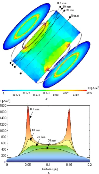
The current density distribution in a plane perpendicular to the circular electrode surface is shown in Fig. 6a. The peak densities at the electrodes periphery decrease rela-tively rapidly with depth in the 'thorax' domain. To better observe this effect, several detailed profiles are taken along the dotted axes, marked in the vertical-section plane, at
0.5, 10, 20 and 50 mm depth under the interfacing layer surface (Fig. 6b).
Various electrode configurations
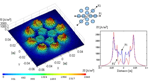
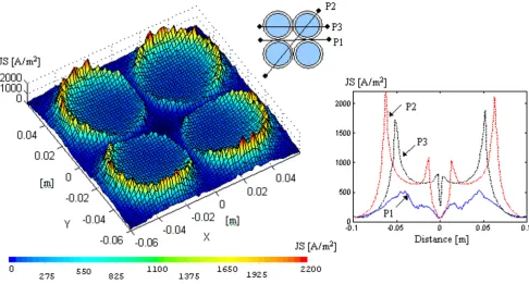
Electrodes of various shapes were designed, presumably more suitable for long-term wearing. Their respective shape and distribution profiles are shown in Figs. 7,8,9,10,11. The electrodes of Fig. 7, 10 and 11 are circular (5 cm radius; 0.5 mm interface layer thickness; ρ = 20 Ωm) with openings for improvement of skin aeration. We also simulated an electrode where the openings were replaced by conductive elements (Fig. 8). The four circular elec-trodes in Fig. 9, each surrounded by an additional ring, are of the same total area as the 5 cm radius circular electrode Table 1: Comparative results for two electrodes with different radii.
Electrode Radius [cm] Interfacing layer (5 mm thickness) Jmax/Jmin [Am-2] K=Jmax/Jmin
ρ [Ωm] R [Ω ]
5 20 1.25 1780/570 3.12
2.5 4 1.25 2450/800 3.06
5 80 5.1 1490/550 2.71
2.5 20 5.1 2150/780 2.76
Figure 5
BioMedical Engineering OnLine 2002, 1 http://www.biomedical-engineering-online.com/content/1/1/7
Figure 6
Figure 7
Current density distribution for a circular electrode with aeration openings. Right-side graphs – profiles along selected axes.
Figure 8
BioMedical Engineering OnLine 2002, 1 http://www.biomedical-engineering-online.com/content/1/1/7
Figure 9
Current density distribution for a four-disk electrode with additional high-resistivity rings. Right-side graphs – profiles along selected axes.
Figure 10
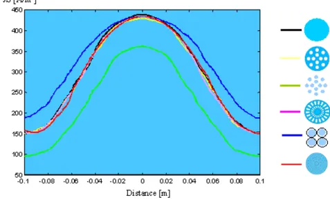
of Fig. 4. The "non-uniformity" coefficient of the current density distribution profile reaches very high values (K > 11) in a plane 0.5 mm below the interfacing gel. The per-formance of each electrode configuration was assessed also by the current distribution profile along an axis in the central region, at 50 mm depth in the 'thorax' domain (Fig. 12).
Discussion
Commonly used rectangular electrodes (area ~80 cm2)
ex-hibit high non-uniformity of the current density distribu-tion at the electrode-skin interface. The profile across the corners shows a non-uniformity coefficient of 4.6 (Fig. 2a). The standard circular electrode with the same area yields 32% lower non-uniformity (Fig. 2b).
Smaller electrodes produce higher current density, with slightly lower non-uniformity (Fig. 3). However, the elec-trode radius cannot be less than 4.7 cm for the minimum area of 70 cm2, recommended for efficient defibrillation.
The resistance of the electrode-skin interfacing layer is a major determinant of the maximum current density in the distribution profile. Two electrodes with different radii show equal non-uniformity, assessed by the coefficient K=
Jmax/Jmin, if the under-electrode layer specific resistivity is chosen to provide the same electrode resistance (Table 1). This result was confirmed also for interfacing layers of different thicknesses (Fig. 5). For example, a thick layer with lower specific resistance (ρ = 20 Ωm and 1.5 mm thickness) has the same performance as a thin layer with higher ρ (ρ = 60 Ωm and 0.5 mm thickness). This result did not confirm our expectations that the thickness of the interface has a certain straightening effect on the current lines. A higher layer resistance is associated with lower non-uniformity, but it should not add more than 3–5% to the total resistance of the defibrillation current path. Many authors investigated the advantage of covering the electrode metal with resistive layers of increasing resistivi-ty toward the periphery [14,21]. Such a technique seems technologically difficult and expensive for disposable electrodes. The use of a ring of higher resistivity along the electrode perimeter seems acceptable, as the resistance in the current pathway was not increased, the maximum pe-riphery current was reduced by 12% and the non-uni-formity coefficient dropped to K = 2.71 (1570/580 A/m2).
The same result could be achieved with 3 times higher re-sistance of a uniform layer. However, the problem of tech-nological difficulties remains open.
Figure 11
BioMedical Engineering OnLine 2002, 1 http://www.biomedical-engineering-online.com/content/1/1/7
Various electrode structures with openings for skin "breathing" (Figs. 7,8,9,10,11), increase the effect of non-uniformity, as the current density under the vents drops strongly. However, the distribution non-uniformity be-comes negligible with increased distance from the elec-trode surface, as evident in Fig. 6. The bell-shaped distribution in Fig. 12 is estimated for the central region of the cylindrical thorax model, 50 mm under the interfac-ing layer surface. Consequently, the current density distri-bution under various electrode structures relates to effects on the skin, rather than to the defibrillation efficiency.
Conclusion
The current density distribution non-uniformity of circu-lar electrodes is about 30% smaller than that of square-shaped electrodes. The use of an interface layer of interme-diate resistivity, comparable to that of the underlying tis-sues can further improve the distribution. A high-resistivity perimeter ring adds a further 13% improvement without increasing the total interface resistance, hence the
resistance to the defibrillation current, which is an impor-tant advantage in defibrillation.
The inclusion of skin aeration openings for wearable elec-trodes disturbs the current paths, but an appropriate selec-tion of number and size provides a reasonable compromise.
Authors' contributions
VTK solved the problems of adequate FEM modeling, the development of various electrode configurations, and generation and presentation of the current distribution profiles. SPP was responsible for the theoretical basis of the investigation and for the setting the main ideas in the solution analysis. Both authors read and approved the fi-nal manuscript.
Acknowledgements
The authors would like to express their deep gratitude to Prof. I. Daskalov for the scientific guidance and help in the biomedical engineering aspect of the study. The authors thank the Technical University of Sofia for granting Figure 12
Publish with BioMed Central and every scientist can read your work free of charge "BioMed Central will be the most significant development for disseminating the results of biomedical researc h in our lifetime."
Sir Paul Nurse, Cancer Research UK
Your research papers will be:
available free of charge to the entire biomedical community
peer reviewed and published immediately upon acceptance
cited in PubMed and archived on PubMed Central
yours — you keep the copyright
Submit your manuscript here:
http://www.biomedcentral.com/info/publishing_adv.asp
BioMedcentral
References
1. International Liaison Committee on Resuscitation Guidelines 2000 for Cardiopulmonary Resuscitation and Emergency Cardio-vascular Care.Circulation 2000, 102:I86-90
2. Geddes LA Electrodes for transchest and ICD defibrillation and multifunctional electrodes.In: Defibrillation of the heart. ICDs, AEDs and Manual(Edited by: Tacker WA) Mosby, St Louis 1994, 82-118 3. Fahy BJ Optimal electrode configurations for external cardiac pacing and defibrillation: an inhomogeneous study.IEEE Trans-actions on Biomedical Engineering 1987, 34:743-748
4. Lehr JL, Ramirez IF, Karlon WJ and Eisenberg SR Test of four defi-brillation dosing strategies using a two-dimensional finite-el-ement model.Medical & Biological Engineering & Computing 1992,
30:621-628
5. Camacho MA, Lehr JL and Eisenberg WJ A three-dimensional fi-nite element model of human transthoracic defibrillation: paddle placement and size.IEEE Transactions on Biomedical Engi-neering 1995, 42:572-578
6. Panescu D, Webster JG, Tompkins WJ and Stratbrucker RA Optimi-zation of cardiac defibrillation by three dimensional finite el-ement modelling of the human thorax.IEEE Transactions on Biomedical Engineering 1995, 42:185-191
7. Jorgenson DB, Haynor DR, Bardy GH and Kim Y Computational studies of transthoracic and transvenous defibrillation in a detailed 3D human thorax model.IEEE Transactions on Biomedical Engineering 1995, 42:172-183
8. Wiley JD and Webster JG Analysis and control of the current distribution under circular dispersive electrodes.IEEE Transac-tions on Biomedical Engineering 1982, 29:381-385
9. Wiley JD and Webster JG Distributed equivalent-circuit model for circular dispersive electrodes.IEEE Transactions on Biomedical Engineering 1982, 29:385-389
10. McNaughton GW, Wyatt JP and Byrne JC Defibrillation – a burn-ing issue in coronary care units.Scottish Medical Journal 1996,
41:47-48
11. Battig CG Electrosurgical burns and their prevention. JAMA
1968, 204:1025-1029
12. Pagan-Carlo LA, Stone MS and Kerber RE Nature and determi-nants of skin 'burns' after transthoracic cardioversion.Am J Cardiology 1997, 79:689-691
13. Vogel U, Wanner T and Bultmann B Extensive pectoral muscle necrosis after defibrillation: nonthermal skeletal muscle damage caused by electroporation.Intensive Care Medicine 1998,
24:743-745
14. Kim Y and Schimpf PH Electrical behavior of defibrillation and pacing electrodes.Proceedings of the IEEE 1996, 84:446-456 15. Birkui PJ, Trigano LA, Zoll PM and eds Noninvasive
transcutane-ous cardiac pacing.Futura Publ IncMount Kisco, New York 1992, 179-191
16. Garcia LA, Pagan-Carlo LA, Stone MS and Kerber RE High perime-ter impedance defibrillation electrodes reduce skin burns in transthoracic cardioversion.American Journal of Cardiology 1998,
82:1125-1127
17. Schott R Wearable defibrillator.Cardiovasc J Nurs 2002, 16:44-52 18. Totman M, O'Leary J, Owen JM and Fincke RW Defibrillation
sys-tem.US Patent No 6374138 2002,
19. Tacker WA and Geddes LA The laws of electrical stimulation of cardiac tissue.Proceedings of the IEEE 1996, 84:355-65
20. Al Hatib F, Trendafilova E and Daskalov I Thransthoracic electri-cal impedance during external defibrillation: comparison of measured and modeled waveforms.Physiological Measurement
2000, 21:145-153
21. Papazov S, Kostov Z and Daskalov I Electrical current distribu-tion under transthoracic defibrilladistribu-tion and pacing electrodes.