EXACT ANALYTICAL SOLUTION FOR BENDING ANALYSIS
OF FUNCTIONALLY GRADED ANNULAR
SECTOR PLATES
A.R. Saidi*, E. Jomehzadeh and S.R. Atashipour
Department of Mechanical Engineering, Shahid Bahonar University of Kerman P.O. Box 76175-133, Kerman, Iran
[email protected] – [email protected] – [email protected]
*Corresponding Author
(Received: July 27, 2008 – Accepted in Revised Form: February 19, 2009)
Abstract In this article, an exact levy solution is presented for bending analysis of a functionally graded (FG) annular sector plate. The governing equilibrium equations are obtained based on the classical plate theory. Introducing an analytical method for the first time, the three coupled governing equilibrium equations are replaced by an independent equation in term of transverse deflection. This equation which is a forth-order partial differential equation is similar to the governing equilibrium equation of a homogeneous isotropic annular sector plate. Using an equivalent flexural rigidity, the solutions of FG annular sector plates can be easily extracted from equation of homogeneous annular plates. Finally, the effects of the exponents of the power functions, aspect ratio, inner to outer radius ratio and boundary conditions on the mechanical behavior of a functionally graded annular sector plate are discussed.
Keywords Bending Analysis, Functionally Graded Materials, Annular Sector Plate, Analytical Method
ﻩﺪﻴﻜﭼ
ﻕﺭﻭﺶﻤﺧﻞﻴﻠﺤﺗﻱﺍﺮﺑﻱﻮﻟﻖﻴﻗﺩﻞﺣ،ﻖﻴﻘﺤﺗﻦﻳﺍﺭﺩ ﻪﺘﺧﺎﺳﻲﻟﺎﺧﻮﺗﻲﻋﺎﻄﻗﻱﺎﻫ
ﺪﻨﻤﻓﺪﻫﺩﺍﻮﻣﺯﺍﻩﺪﺷ
ﻪﺿﺮﻋ ﺖﺳﺍﻩﺪﺷ
.
ﻢﮐﺎﺣﺕﻻﺩﺎﻌﻣ ﺮﺑ
ﺮﺑﻝﺩﺎﻌﺗ ﺑﻕﺭﻭﮏﻴﺳﻼﮐﻱﺭﻮﺌﺗﺱﺎﺳﺍ ﻪ
ﻩﺪﻣﺁﺖﺳﺩ ﺪﻧﺍ
.
ﺵﻭﺭﮏﻳﻲﻓﺮﻌﻣﺎﺑ
ﻟﺩﺎﻌﻣﻪﺳ،ﺭﺎﺑﻦﻴﻟﻭﺍ ﻱﺍﺮﺑﻲﻠﻴﻠﺤﺗ ﺔ
ﻪﺑﻪﺘﺴﺑﺍﻭ ﻝﺩﺎﻌﺗ ﻟﺩﺎﻌﻣﮏﻳﻪﺑﻞﻳﺪﺒﺗ ،ﻢﻫ
ﺔ ﺮﺑ ﻞﻘﺘﺴﻣ ﺎﺟ ﺐﺴﺣ ﺑﻪ
ﻲﺒﻧﺎﺟ ﻲﻳﺎﺟ
ﻲﻣ ﺪﻧﻮﺷ
.
ﻪﻟﺩﺎﻌﻣﻦﻳﺍ ، ﻟﺩﺎﻌﻣﮏﻳ ﺔ ﻩﺭﺎﭘﻞﻴﺴﻧﺍﺮﻔﻳﺩ ﺭﺎﻬﭼﻪﺒﺗﺮﻣﻱﺍ
ﻭ ﻟﺩﺎﻌﻣﻪﺑﺎﺸﻣ ﺔ
ﻢﮐﺎﺣ ﺮﺑ ﺩﺮﮔﻥﺎﺴﻤﻫﻦﮕﻤﻫﻕﺭﻭ
ﺖﺳﺍ
.
ﺎﺑ ﻩﺩﺎﻔﺘﺳﺍ ﻪﺘﺧﺎﺳﻲﻟﺎﺧﻮﺗﻲﻋﺎﻄﻗﻕﺭﻭﺦﺳﺎﭘ،ﻝﺩﺎﻌﻣﻲﺸﻤﺧﻲﺘﻔﺳﮏﻳﺯﺍ ﻲﻣﺍﺭﺪﻨﻤﻓﺪﻫﺩﺍﻮﻣﺯﺍﻩﺪﺷ
ﺯﺍﻥﺍﻮﺗ
ﻣ ﻢﮐﺎﺣﺕﻻﺩﺎﻌ ﺮﺑ
ﺑﺩﺮﮔﻥﺎﺴﻤﻫﻕﺭﻭ ﻪ
ﺩﺭﻭﺁﺖﺳﺩ
.
ﺭﺩ،ﺎﻬﺘﻧﺍﺭﺩ ﺓﺭﺎﺑ
ﻪﺑﺖﻣﺎﺨﺿ ﺖﺒﺴﻧ،ﺪﻨﻤﻓﺪﻫﻩﺩﺎﻣﻥﺍﻮﺗﺕﺍﺮﺛﺍ
ﺮﺑ ﻱﺯﺮﻣ ﻂﻳﺍﺮﺷﻭﻲﺟﺭﺎﺧ ﻪﺑ ﻲﻠﺧﺍﺩ ﻉﺎﻌﺷ ﺖﺒﺴﻧ ،ﻉﺎﻌﺷ ﻪﺘﺧﺎﺳ ﻲﻟﺎﺧﻮﺗ ﻲﻋﺎﻄﻗ ﻕﺭﻭ ﺭﺎﺘﻓﺭ ﻱﻭﺭ
ﺩﺍﻮﻣﺯﺍ ﻩﺪﺷ
ﺖﺳﺍﻩﺪﺷﺚﺤﺑﺪﻨﻤﻓﺪﻫ
.
1. INTRODUCTION
A new class of materials known as “functionally graded materials” (FGMs) has been introduced in which the material properties vary continuously in one or more directions according to a specific profile. These materials are microscopically heterogeneous and are typically made of isotropic components such as metals and ceramics. FGMs exploit the ideal performance of their composition, e.g. heat and corrosion resistance of ceramics on one side, and mechanical strength and toughness of metals on the other side of a body [1].
Thin plates are light weight structures with high
(DQM). The axisymmetric bending and stretching analysis of functionally graded (FG) solid and annular circular plates was studied by Reddy, et al [3] using the first order shear deformation Mindlin plate theory. Cheng, et al [4] derived a three-dimensional thermoelastic analysis for functionally graded elliptic plates. The analysis of the functionally graded plates based on classical plate theory was developed by Chi, et al [5,6]. They presented the solution for simply supported P-FG and S-FG rectangular plates. Abrate [7,8] showed that no special tools are required to study the analysis of functionally graded rectangular plates because they behave like homogeneous plates. He selected a different reference surface instead of middle surface and showed that based on this surface the static and vibration analysis of FG plates and homogeneous plates are related to each other. An approximate closed-form solution was presented for bending of thin isotropic sector plates with clamped edges subjected to uniform and non-uniform loading using the extended Kantorovich method (EKM) by Aghdam, et al [9]. Nie, et al [10] investigated the free and forced vibration of functionally graded annular sector plates with simply supported radial edges and arbitrary boundary conditions along the circular edges. They studied an approximate solution along the radial direction using the one-dimensional differential quadrature method (DQM). The meshless local Petrov–Galerkin (MLPG) method was used for analyzing two-dimensional static and dynamic deformations of functionally graded materials with material response modeled as either linear elastic or as linear viscoelastic by Gilhooley, et al [11]. Sahraee [12] presented the bending analysis of functionally graded circular sector plates based on the Levinson plate theory. He ignored the middle plane displacement of the FG sector plate and solved the problem similar to the isotropic one. A two-dimensional higher-order deformation theory was presented for the evaluation of displacements and stresses in functionally graded plates subjected to thermal and mechanical loadings by Matsunaga [13]. Zhang, et al [14] presented a theoretical analysis to the FG thin rectangular plates based on the physical neutral surface. Jomehzadeh, et al [15,16] studied the vibration analysis of laminated sector and annular sector plates made of transversely isotropic layers. Saidi, et al [17] introduced an analytical method for decoupling the equilibrium equations of Kirchhoff
and Mindlin rectangular plates.
Many investigations dealing with static and dynamic behaviors of isotropic and functionally graded rectangular plates can be found in literature. However, no such work can be found for analysis of FG annular sector plate. In this study, the static analysis of functionally graded annular sector plates is presented based on classical plate theory. Using an analytical method, three coupled stretching and bending equilibrium equations of FG annular sector plates are decoupled. Solving the decoupled equation, the solution of FG annular sector plates is obtained. It is found that using an equivalent flexural rigidity, the decoupled equation of FG annular sector plates becomes similar to the equilibrium equation of isotropic plates in polar coordinates. The variations of some physical parameters are shown for different functionally graded materials.
2. THE MATERIAL PROPERTIES OF FG ANNULAR SECTOR PLATES
The annular sector plate material is made of a mixture of ceramic and metal. It is assumed that the Young modulus of the annular sector plate vary as a power law through the thickness as [18]
p ) h / z 2 / 1 )( m E c E ( m E ) z (
E = + − − (1)
Where E(z) is the Young modulus of the annular sector plate, h is the total thickness of the plate, p
is the power of FG plate, Em is the Young modulus at z=h/2 (pure metal) and Ec represents the Young modulus at z=−h/2 (pure ceramic). According to the small range of Poisson ratio variation, it is assumed to be constant through the thickness of the FG annular sector plate [3,5,12].
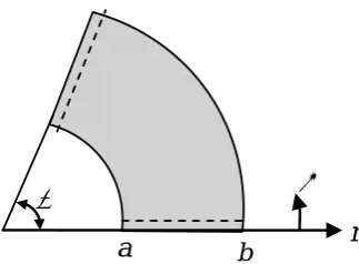
2.1. Governing Equilibrium Equations of
Annular Sector Plates
Consider a FG annularThe displacement components of the plate in r,
θ and z directions are assumed as
r w z ) , r ( u ) z , , r ( r u ∂ ∂ − θ =
θ (2a)
θ ∂ ∂ − θ = θ
θ(r, ,z) v(r, ) zr w
u (2b)
) , r ( w ) z , , r (
w θ = θ (2c)
Where u, v and w are the displacements of middle surface in r, θ and z directions, respectively. Under the assumption of small deformation and linear strain-displacement relations, the strain components of a FG annular sector plate can be expressed as
) w 2 r 2 r w 2 r 2 ( z r v r v u r 1 r 2 ) r w r 1 2 w 2 2 r 1 ( z r u v r 1 ) r 2 w 2 ( z r u r θ ∂ ∂ + θ ∂ ∂ ∂ − + − ∂ ∂ + θ ∂ ∂ = θ ε ∂ ∂ − θ ∂ ∂ − + + θ ∂ ∂ = θ ε ∂ ∂ − + ∂ ∂ = ε (3)
In classical plate theory, it is assumed that the cross section perpendicular to the middle surface of the plate remains normal and unstretched after deformation. Consequently, the transverse shear deformations are neglected and the shear strain components 2εrz and 2εθz vanish.
Substituting strain components (3) into the principle of minimum potential energy, the equilibrium equations of Kirchhoff plate in polar
coordinates are obtained as
0 ) N r N ( r 1 r N r 1 rr N = θ − + θ ∂ θ ∂ + ∂ ∂ (4a) 0 N r 1 r N r 2 r r N = θ ∂ θ ∂ + θ + ∂ θ ∂ (4b) 0 ) , r ( P r M 2 r 2 r r M 2 r 2 r M r 1 2 M 2 2 r 1 rr M r 2 2 r r M 2 = θ + θ ∂ θ ∂ + θ ∂ ∂ θ ∂ + ∂ θ ∂ − θ ∂ θ ∂ + ∂ ∂ + ∂ ∂ (4c)
Where P(r,θ) is the external loading function and the resultant forces Nr, Nθ and Nrθ can be defined by integrating corresponding stresses along the thickness as follows
∫ − θ σ = θ ∫ − θ σ = θ ∫ − σ = 2 / h 2 / h dz r r N , 2 / h 2 / h dz N , 2 / h 2 / h dz r r N (5)
and the resultant moments Mr, Mθ and Mrθ are
∫ − θ σ = θ ∫ − θ σ = θ ∫ − σ = 2 / h 2 / h dz z r r M , 2 / h 2 / h dz z M , 2 / h 2 / h dz z r r M (6)
Considering plane stress state for the FG annular sector plate, the stresses are defined as
) r ( 2 1 ) z ( E
r = −ν ε +νεθ
σ (7a)
) r ( 2 1 ) z (
E +νε
θ ε ν − = θ
σ (7b)
) r 2 ( ) 1 ( 2 ) z ( E
rθ= +ν εθ
σ (7c)
α
θ
r
a
bUsing Equations 3, 7 and the definition of resultant forces and moments in Equations 5 and 6, one can obtain ⎥ ⎥ ⎥ ⎥ ⎥ ⎥ ⎥ ⎥ ⎦ ⎤ ⎢ ⎢ ⎢ ⎢ ⎢ ⎢ ⎢ ⎢ ⎣ ⎡ θ ∂ ∂ + θ ∂ ∂ ∂ − ∂ ∂ − θ ∂ ∂ − ∂ ∂ − − ∂ ∂ + θ ∂ ∂ + θ ∂ ∂ ∂ ∂ ⎥ ⎥ ⎥ ⎥ ⎥ ⎥ ⎥ ⎥ ⎦ ⎤ ⎢ ⎢ ⎢ ⎢ ⎢ ⎢ ⎢ ⎢ ⎣ ⎡ = ⎥ ⎥ ⎥ ⎥ ⎥ ⎥ ⎥ ⎥ ⎦ ⎤ ⎢ ⎢ ⎢ ⎢ ⎢ ⎢ ⎢ ⎢ ⎣ ⎡ θ θ θ θ 2 r / w 2 r r / w 2 2 r r / w 2 2 r / w 2 2 r / w
2 v/ r v/r r / u r / u r / v r / u 66 D 0 0 66 B 0 0 0 22 D 12 D 0 22 B 12 B 0 12 D 11 D 0 12 B 11 B 66 B 0 0 66 A 0 0 0 22 B 12 B 0 22 A 12 A 0 12 B 11 B 0 12 A 11 A r M Mr Mr N Nr N (8)
Where the integration coefficients Aij, Bij and Dij ) 3 , 2 , 1 j ,i
( = are defined as
∫ − ν + = ∫ − ν − ν = ∫ − ν − = 2 / h 2 / h dz ) z ( E ) 1 ( 2 1 33 A , 2 / h 2 / h dz ) z ( E 2 1 12 A , 2 / h 2 / h dz ) z ( E 2 1 1 11 A (9a) ∫ − ν + = ∫ − ν − ν = ∫ − ν − = 2 / h 2 / h dz ) z ( zE ) 1 ( 2 1 33 B , 2 / h 2 / h dz ) z ( zE 2 1 12 B , 2 / h 2 / h dz ) z ( zE 2 1 1 11 B (9b) ∫ − ν + = ∫ − ν − ν = ∫ − ν − = 2 / h 2 / h dz ) z ( E 2 z ) 1 ( 2 1 33 D , 2 / h 2 / h dz ) z ( E 2 z 2 1 12 D , 2 / h 2 / h dz ) z ( E 2 z 2 1 1 11 D (9c)
Substituting resultant forces and moments obtained in Equations 8 into the Equations 4, the governing equilibrium equations are obtained as
0 ) 2 w 2 3 r 1 2 r w 3 2 r 1 2 w 2 3 r 1 r w 2 r 1 2 r w 2 r 1 3 r w 3 ( 11 B ) v 2 r 1 r v 2 r 1 2 u 2 2 r 1 ( 33 A ) r v 2 r 1 v 2 r 1 2 r u r u r 1 2 r u 2 ( 11 A = θ ∂ ∂ + θ ∂ ∂ ∂ − θ ∂ ∂ + ∂ ∂ + ∂ ∂ − ∂ ∂ − θ ∂ ∂ − θ ∂ ∂ ∂ − θ ∂ ∂ + θ ∂ ∂ ∂ + θ ∂ ∂ − − ∂ ∂ + ∂ ∂ (10a) 0 ) 3 w 3 3 r 1 r w 2 2 r 1 2 r w 3 r 1 ( 11 B ) r u 2 r 1 u 2 r 1 2 r v r v r 1 2 r v 2 ( 33 A ) u 2 r 1 r u 2 r 1 2 v 2 2 r 1 ( 11 A = θ ∂ ∂ − θ ∂ ∂ ∂ − θ ∂ ∂ ∂ − θ ∂ ∂ ∂ − θ ∂ ∂ + − ∂ ∂ + ∂ ∂ + θ ∂ ∂ + θ ∂ ∂ ∂ + θ ∂ ∂ (10b) 0 ) , r ( P ) 4 w 4 4 r 1 2 w 2 4 r 4 2 r w 3 3 r 2 2 2 r w 4 2 r 2 r w 3 r 1 2 r w 2 2 r 1 3 r w 3 r 2 4 r w 4 ( 11 D ) 2 r v 3 r 1 3 v 3 3 r 1 v 3 r 1 r v 2 2 r 1 2 r u 3 2 r 1 2 u 2 3 r 1 3 r u r u 2 r 1 2 r u 2 r 2 3 r u 3 ( 11 B = θ + θ ∂ ∂ + θ ∂ ∂ + θ ∂ ∂ ∂ − θ ∂ ∂ ∂ + ∂ ∂ + ∂ ∂ − ∂ ∂ + ∂ ∂ − θ ∂ ∂ ∂ + θ ∂ ∂ + θ ∂ ∂ + θ ∂ ∂ ∂ − θ ∂ ∂ ∂ + θ ∂ ∂ + + ∂ ∂ − ∂ ∂ + ∂ ∂ (10c)
Equations 10 are three highly coupled equations in terms of in-plane and transverse displacements. For solving such coupled equations, it is reasonable to find a method for decoupling them. Using an analytical method, three equilibrium Equations 10 are decoupled. Equations 10 can be rewritten as follows 0 ) w 2 ( r 11 B 2 r 1 33 A r1 11
A ∇ =
∂ ∂ − θ ∂ ϕ ∂ + ∂ ϕ ∂ (11c) 0 ) w 2 ( r 11 B r2 33 A 1 r 1 11
A ∇ =
0 ) , r ( P w 2 2 11 D 1 2 11
B ∇ ϕ − ∇ ∇ + θ = (11c)
Where ∇2 is two dimensional Laplace operator in polar coordinates (∇2=∂2/∂r2+∂/r∂r+∂2/r2∂θ2)
and the variables ϕ1 and ϕ2 are defined as
θ ∂ ∂ + + ∂ ∂ =
ϕ v
r 1 r u r u
1 (12a)
r v r v u r 1
2 ∂ −
∂ − θ ∂ ∂ =
ϕ (12b)
Differentiating of Equation 11b with respect to θ
and dividing by r and differentiating Equation 11a with respect to r and then adding the two results, yields
w 4 11 B 1 2 11
A ∇ ϕ = ∇ (13)
Upon substitution of Equation 13 into the last governing equilibrium Equation 11c, yields
) , r ( P w 4 ) 11 A
2 11 B 11 D
( − ∇ = θ (14)
Equation 14 is an independent forth-order partial differential equation in term of transverse displacement, w. This equation is very similar to the equation of isotropic homogenous Kirchhoff plate. Introducing an equivalent flexural rigidity, the decoupled governing equilibrium equation of FG annular sector plate (Equation 14) becomes identical to the governing equation of isotropic homogeneous annular sector plate. The Equation 14 can be rewritten as
) , r ( P w 4
Dˆ∇ = θ (15)
Where Dˆ is the equivalent flexural rigidity of the FG annular sector plate which is equal to
11 2 11
11 B /A
D − . The coefficients A11, B11 and D11
can be defined in terms of the material properties of the FG annular sector plate from Equations 1 and 9 as follows
⎟ ⎟ ⎠ ⎞ ⎜
⎜ ⎝ ⎛
+ + ν
− =
1 p
cm E m E 2 1
h
A (16a)
⎟⎟ ⎠ ⎞ ⎜⎜
⎝ ⎛
+ + ν
− − =
) 2 p )( 1 p ( 2
p 2
1 2 h cm E
B (16b)
) 3 p )( 2 p )( 1 p )( 2 1 ( 4
) 2 p 2 p ( 3 h cm E
) 2 1 ( 12
3 h m E D
+ + + ν −
+ + +
ν −
= (16c)
Also, differentiating Equation 11a with respect to
θ and dividing by r and differentiating Equation 11b with respect to r and then subtracting the two results from each other, yields
0 2 2ϕ =
∇ (17)
Due to Equations 13 and 17 and the definition of variables ϕ1 and ϕ2 in Equation 12, it can be concluded that these equations are satisfied by letting the in-plane displacements as follows
r w 11 A
11 B u
∂ ∂
= (18a)
θ ∂ ∂ =
r w 11 A11 B
v (18b)
It is easy to show that relations (18) satisfy Equations 13 and 17 and all boundary conditions along the edges of the plate. Substituting these middle plane displacements into Equation 2, the proposed displacement field of FG Kirchhoff annular sector plate becomes as
r w ) z 11 A / 11 B ( ) z , , r ( r u
∂ ∂ − =
θ (19a)
θ ∂ ∂ − =
θ
θ(r, ,z) (B11/A11 z)1r w
u (19b)
) , r ( w ) z , , r (
w θ = θ (19c)
plane. It can be seen from Equation 19 that the in-plane displacements of the plate at z=B11/A11 are vanished. The surface located at z=B11/A11 is the neutral surface of the FG annular sector plate. In fact, the neutral surface of the FG plates depends on the variation of material properties in the thickness direction and the location of the neutral surface is independent of the geometric parameters.
Based on the obtained displacement field for FG annular sector plate (Equation 19), the resultant moments can be obtained in the form
) ) 2 w 2 2 r
1 r r
w ( r w ( Dˆ r M
θ ∂ ∂ + ∂ ∂ ν + ∂ ∂
= (20a)
) r w 2 w 2 2 r
1 r r
w ( Dˆ M
∂ ∂ ν + θ ∂ ∂ + ∂ ∂ =
θ (20b)
) w 2 r
1 r
w 2 r 1 )( 1 ( Dˆ r M
θ ∂ ∂ + θ ∂ ∂ ∂ ν − =
θ (20c)
Where the parameter Dˆ is the equivalent flexural rigidity as mentioned before.
2.2. Solution
For static analysis of the FGannular sector plate which is simply supported at two radial edges, the transverse displacement and uniformly distributed load can be represented as
) m sin( ,..
3 , 1
m wm(r)
) , r (
w ∞∑ β θ
= =
θ (21a)
) m sin( ,...
3 , 1
m m
0 p 4 )
, r (
P ∑∞ β θ
= π
=
θ (21b)
Where βm denotes mπ/α. Substituting the proposed series solutions (21) into Equation 15 and solving the resulting ordinary differential equation, yields
) m sin(
) 64 2 m 20 4 m ( Dˆ m
4 r 0 p 4 2
m r 4 C
2 m r 3 C m r 2 C m r 1 C
) r ( m w
θ β
⎟⎟ ⎟ ⎟ ⎟ ⎟
⎠ ⎞
⎜⎜ ⎜ ⎜ ⎜ ⎜
⎝ ⎛
+ β − β π + + β
+ + β − + β − + β
=
(22)
Imposing arbitrary boundary conditions at inner (r=a) and outer (r=b) circular edges, the four unknown coefficients (C1,C2,C3,C4,) can be determined.
3. NUMERICAL RESULTS AND DISCUSSION
For simplicity and generality, the following non-dimensional terms are introduced
2 b 0 p
2 h ) 2 / , 2
b a (
, 2 b 0 p
2 h ) 2 / , 2
b a ( r r
, h
) 2 / , r ( w w
α + θ σ = θ σ
α + σ = σ
α =
(23)
In numerical calculation, the FG annular plate is assumed to have simply supported radial edges. The inner radius, outer radius and thickness of the annular plate are considered to be a = 2.5, b = 10 and h = 0.2, respectively. The Poisson ratio of the plate is assumed to be constant through the thickness and equal to 0.3. The functionally graded material used is composed of aluminum with Em = 70 Gpa and Silicon Carbide with Ec = 420 Gpa. The plate is subjected to uniformly distributed load with intensity of p0 = 1 × 10⁴ N/m2.
The boundary conditions are identified according to the inner and outer radius of the annular sector plates (e.g. F-C denotes free inner and clamped outer edges).
vanish at the mid-plane of the FG annular sector plates. The normal stress in r direction is equal to zero at neutral surface which is located at z=B/A
as discussed. Also, the stress components of the FG annular sector plates along the thickness direction are not linearly proportional to z
direction.
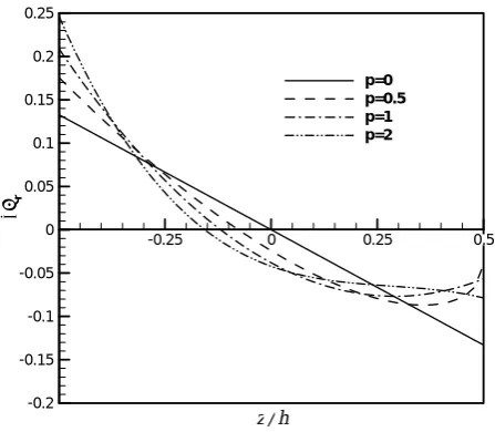
The variation of non-dimensional radial stress
)
(σr is depicted in Figure 5 through the thickness direction for different powers of functionally graded material (p). The plate is assumed to have clamped edges in two circular edges. It can be seen that for p equal to 3.5, the non-dimensional stress is vanished in far distance from the middle plane. It can be easy to show that the parameter B/A has maximum value at p = 3.5.
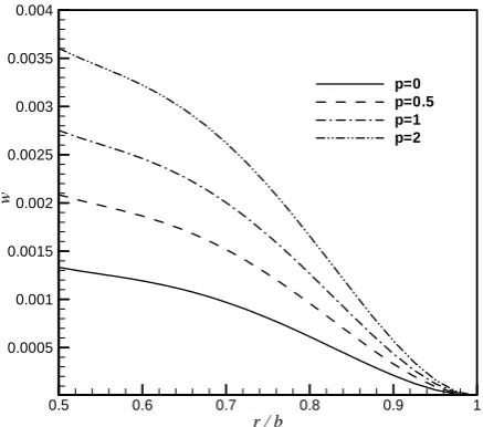
The non-dimensional transverse displacement is
r / b
⎯
w
0.3 0.4 0.5 0.6 0.7 0.8 0.9 1
0 0.0005 0.001 0.0015 0.002 0.0025 0.003 0.0035 0.004 0.0045
p=0 p=0.5 p=1 p=2
Figure 2. Non-dimensional deflection along radial direction (S-S).
z / h
⎯σr
-0.25 0 0.25 0.5
-0.2 -0.15 -0.1 -0.05 0 0.05 0.1 0.15 0.2 0.25
p=0 p=0.5 p=1 p=2
Figure 3. Non-dimensional radial stress along thickness direction (S-S).
z / h
⎯σθ
-0.25 0 0.25 0.5
-0.2 -0.15 -0.1 -0.05 0 0.05 0.1 0.15 0.2 0.25 0.3
p=0 p=0.5 p=1 p=2
Figure 4. Non-dimensional circumferential stress along thickness direction (S-S).
z / h
⎯σr
-0.25 0 0.25 0.5
-0.1 -0.05 0 0.05 0.1 0.15 0.2
p=0.5 p=1 p=2 p=3.5 p=24
shown for a/b = 0.25 and a/b = 0.5 in Figures 6 and 7 respectively. It can be seen that when the inner edge of the annular plate is close to the center of the annular sector plate, the maximum deflection does not occur at the free edge. However, approaching the inner edge to outer one, the maximum non-dimensional deflection occurs at free inner edge. This is acceptable because with
decreasing the inner radius, the length of the free inner edge decreases and the annular sector plate becomes stiffer.
In order to see the variation of the circumferential stress along the θ direction, the non-dimensional stress , ,h/2)
2 b a
( + θ
σθ is depicted along the
circumferential direction for different powers of FGM in Figure 8. It can be seen that the maximum stress is due to the homogeneous annular sector plate.
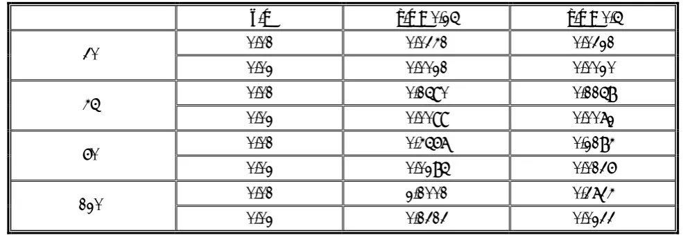
The maximum non-dimensional transverse deflection is tabulated for different sector angles and some aspect ratios and inner to outer radius ratios in Table 1. In this case, the plate has free inner and clamped outer edges and power of FGM is assumed to be 0.5.
4. CONCLUSION
In this paper, an exact analytical solution has been presented for static analysis of functionally graded annular sector plate. The annular sector plate is assumed to have simply supported radial edges and arbitrary boundary conditions along the circular edges. Three coupled governing equilibrium equations of FG annular sector plate have been
r / b
⎯
w
0.3 0.4 0.5 0.6 0.7 0.8 0.9 1
0.0005 0.001 0.0015 0.002 0.0025 0.003
p=0 p=0.5 p=1 p=2
Figure 6. Non-dimensional deflection along radial direction (F-C).
r / b
⎯
w
0.5 0.6 0.7 0.8 0.9 1
0.0005 0.001 0.0015 0.002 0.0025 0.003 0.0035 0.004
p=0 p=0.5 p=1 p=2
Figure 7. Non-dimensional deflection along radial direction (F-C, a/b = 0.5).
θ
⎯σθ
0 10 20 30 40 50 60
-0.08 -0.07 -0.06 -0.05 -0.04 -0.03 -0.02 -0.01 0
p=0 p=0.5 p=1 p=2
Figure 8. Variation of non-dimensional stress (σθ) along
converted to a decoupled equation in term of transverse displacement. Introducing a flexural rigidity, the decoupled equation of FG plate becomes similar to the governing equilibrium equation of isotropic homogeneous plate. Finally, the variation of some parameters has been shown in figures and table.
The exact solution for functionally graded annular sector plate has been obtained for the first time and the present results can be regarded as a database in the field of FG annular sector plates.
5. REFERENCES
1. Shiota, I. and Miyamoto, Y., “Functionally Graded Materials”, Proceedings of the 4th International Symposium on Functionally Graded Materials, (1996),
1-8.
2. Liu, F.L. and Liew, K.M., “Differential Quadrature Element Method for Static Analysis of Reissner-Mindlin Polar Plates”, International Journal of Solids and Structures, Vol. 36, (2000), 5101-5123.
3. Reddy, J.N., Wang, C.M. and Kitipornehai, S., “Axisymmetric Bending of Functionally Graded Circular and Annular Plates”, European Journal of Mechanics A/Solids, Vol. 18, (1999), 185-199.
4. Cheng, Z.Q. and Batra, R.C., “Three-Dimensional Thermoelastic Deformation of a Functionally Graded Elliptic Plate”, Composites Part B, Vol. 31, (2000),
97-106.
5. Chi, S. and Chung, Y., “Mechanical Behavior of Functionally Graded Material Plates Under Transverse Load Part1: Analysis”, International Journal of Solids
and Structures, Vol. 43, (2006), 3657-3674.
6. Chi, S. and Chung, Y., “Mechanical Behavior of Functionally Graded Material Plates Under Transverse Load Part 2: Numerical Results”, International Journal of Solids and Structures, Vol. 43, (2006), 3675-3691. 7. Abrate, S., “Free Vibration, Buckling and Static
Deflections of Functionally Graded Plates”, Composites Science and Technology, Vol. 66, (2006), 2383-2394.
8. Abrate, S., “Functionally Graded Plates Behave Like Homogeneous Plates”, Composites Part B, Vol. 39,
(2008), 151-158.
9. Aghdam, M.M., Mohammadi, M. and Erfanian, V., “Bending Analysis of Thin Annular Sector Plates Using Extended Kantorovich Method”, Thin-Walled Structures,
Vol. 45, (2007), 983-990.
10. Nie, G.J. and Zhong, Z., “Vibration Analysis of Functionally Graded Annular Sectorial Plates with Simply Supported Radial Edges”, Composite Structures, Vol.
84, (2008), 167-176.
11. Gilhooley, D.F., Xiao, J.R., Batra, R.C., McCarthy, M.A. and Gillespie, J.W., “Two-Dimensional Stress Analysis of Functionally Graded Solids Using the MLPG Method with Radial Basis Functions”,
Computational Materials Science, Vol. 41, (2008), 467-481.
12. Sahraee, S., “Bending Analysis of Functionally Graded Sectorial Plates Using Levinson Plate Theory”,
Composite Structures, Vol. 88, (2009), 548-557.
13. Matsunaga, H., “Stress Analysis of Functionally Graded Plates Subjected to Thermal and Mechanical Loadings”,
Composite Structures, Vol. 87, (2009), 344-357.
14. Zhang, D.G. and Zhou, Y.H., “A Theoretical Analysis of FGM Thin Plates Based on Physical Neutral Surface”, Computational Materials Science, Vol. 44,
(2008), 718-720.
15. Jomehzadeh, E. and Saidi, A.R., “Analytical Solution for Free Vibration of Transversely Isotropicsector Plates using a Boundary Layer Function”, Thin-Walled Structures, Vol. 47, (2009), 82-88.
TABLE 1. Maximum Non-Dimensional Deflection for C-F Plate, P = 0.5.
α h/b a/b = 0.25 a/b = 0.5
0.01 0.0341 0.0321 30˚
0.02 0.0021 0.0020 0.01 0.1590 0.1158 45˚
0.02 0.0099 0.0072 0.01 0.4567 0.2184 60˚
0.02 0.0285 0.0136 0.01 2.1001 0.3734 120˚
16. Jomehzadeh, E. and Saidi, A.R., “Accurate Natural Frequencies of Transversely Isotropic Moderately Thick Annular Sector Plates”, Journal of Mechanical Engineering Science, Vol. 223, (2009), 307-317.
17. Saidi, A.R. and Jomehzadeh, E., “On Analytical Approach for the Bending/Stretching of Linearly Elastic Functionally Graded Rectangular Plates with
Two Opposite Edges Simply Supported”, Journal of Mechanical Engineering Science, In Press, Doi:
10.1243/09544062JMES1431.
18. Bao, G. and Wang, L., “Multiple Cracking in Functionally Graded Ceramic/Metal Coatings”,
International Journal of Solids and Structures, Vol.