Available Online at www.ijpret.com 998
INTERNATIONAL JOURNAL OF PURE AND
APPLIED RESEARCH IN ENGINEERING AND
TECHNOLOGY
A PATH FOR HORIZING YOUR INNOVATIVE WORK
COMPARATIVE STUDY OF ROUTING PROTOCOLS IN WIRELESS SENSOR
NETWORK
VIDHI LUHAR, URVI JADHAV, DHARTI PATEL, ASHISH D. PATEL
Dept of Information Technology SVMIT Engineering College Bharuch, India.
Accepted Date: 05/03/2015; Published Date: 01/05/2015
Abstract: In research area of Wireless Sensor Network, protocols are the major and important part. Specifically Data Centric, Location Based and Hierarchical protocol is designed where energy awareness is taken into consideration. This protocol differs depending on the application and network architecture. This paper is intended to discuss the major routing protocols and its comparison. These basic protocols are: Data Centric, Location Based and Hierarchical. Our main focus is on comparison of basic routing protocols and finding most efficient of them. These protocols were basically proposed for wired networks but in order to increase the efficiency of sensor nodes and lifetime, these were then proposed for Wireless Sensor Networks. These protocols also reduce the traffic and overhead as it communicates with particular node and turn offs the sensor nodes which are not in use.
Keywords: Comparison, Wireless sensor network, Routing, Data centric, Hierarchical, Location based, LEACH, PEGASIS
Corresponding Author: MISS. VIDHI LUHAR
Access Online On:
www.ijpret.com
How to Cite This Article:
Available Online at www.ijpret.com 999
INTRODUCTION
WSN is a wide area for research WSN consists of many small sensors which are interconnected by links in network.
In past years, in a sensor network limited numbers of sensor nodes were connected to a central station. But now-a-days more emphasis is laid on wireless and distributed sensor nodes. Due to new emerging technologies, imaginations have turned into reality such as the implementation of small, inexpensive, low-power, distributed devices, which are capable of communicating with each other wirelessly, has got existence. Such nodes are called Sensor Nodes. Ability of sensor nodes have limited processing power when used individually. But in converse when used in group the features of sensor nodes can be used more effectively. Thus sensor nodes can be defined as group of sensor nodes which coordinate to perform some specific task. Unlike traditional networks, sensor networks depend on dense deployment and co-ordination to carry out their tasks. But, why distributed, wireless sensing? [1] Distributed sensing is used to define exact location of the unknown phenomenon. This allows the sensor node to be placed near to the phenomenon which is not possible by a single sensor node. Also, in many cases, multiple sensor nodes are required to overcome environmental obstacles like obstructions, line of sight constraints etc. sometimes environment that we desire for communication does not have required infrastructure. So it becomes essential to communicate wirelessly to survive on small, finite source of energy.
Survey Focus: (related work)
A number of papers propose solutions to one or more of the above problems. Our main focus is on following solutions of above problems:
Energy Efficiency: Energy efficiency is main consideration as sensor nodes have small and limited source of energy. Many solutions, both hardware and software related, have been proposed to optimize energy usage.
Localization: In most of the cases, sensor nodes are deployed in an ad hoc manner. It is up to the nodes to identify themselves in some spatial co-ordinate system. This problem is referred to as localization.
Available Online at www.ijpret.com 1000
ARCHITECTURE OF SENSOR NETWORK:
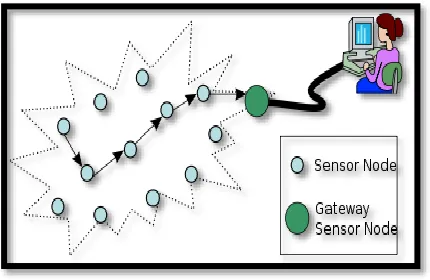
In sensor field sensor nodes are scattered and deployed. The nodes in these networks manage amongst themselves to produce simply accessible and high-quality information about the physical environment. Every sensor node in these networks operates alone with no central point of control and communicates using infrared devices or radios. Each of these scattered sensor nodes has the capabilities to accumulate data and route data back to the sink. A sink may be a long-range radio, capable of connecting the sensor network to existing long-haul communications infrastructure. The sink may act in two way: either as an information sink(node) or a node from which information should be extracted[3]. The sink may communicate with the satellite. The design of the sensor network is influenced by many factors, including fault tolerance, scalability, production costs, hardware constraints, transmission media and power consumption[2][3]
Figure 1 : Architecture of WSN
Routing protocols of wsn
o Data Centric Protocols:
Available Online at www.ijpret.com 1001 In data centric routing, the sink request for data by sending the query so the nearest sensor node transmits the data. Since data is being requested through queries, attribute-based naming is necessary to specify the properties of data. SPINs [5] was the first data centric protocol for data communication between the nodes. After that Directed Diffusion [4] came into picture. Based on these SPIN and Directed Diffusion many other protocols have been proposed like Flooding and Gossiping.
Why Data Centric Protocol is proposed?
To reduce the inefficiency in energy consumption, routing protocols that can select a set of sensor nodes and utilize data aggregation during the relaying of data have been considered. To fulfill this consideration, data-centric routing came into existence, which is different from traditional address-based routing where routes are created between addressable nodes managed in the network layer of the communication stack.
o Location Based Protocol:
In WSN most of the routing protocol requires the location information for sensor nodes in order to transmit data between two nodes and calculating distance between them. Doing this energy conservation can be eliminated. In this kind of network architecture sensor nodes are scattered randomly in area of interest and they are located mostly by the means of GPS. Signal strength received from the nodes are used to estimated between two nodes and coordinates are calculated by exchanging information between neighboring nodes.
o Hierarchical Protocols:
Hierarchical routing protocol was originally developed for wired networks to increase the scalability and efficiency. Hierarchical protocol is also known as Cluster-Based Routing Protocol because these are usually divided into several clusters and each cluster consists of cluster heads and number of cluster membership, multiple cluster heads from level network. In high-level networks, WSN can be divided into clusters, which form a high high-level of network again until sink node of highest level. Hierarchical routing protocol has become the focus of the routing technology with the advantages of convenient topology management, high efficiency energy use, simple data fusion.[6]
Characteristics:
Available Online at www.ijpret.com 1002 Collision Avoidance.
Data Aggregation by cluster heads.
Uniform Energy Dissipation.
Fair location of channel.
Lower latency.
1. LEACH (Low Energy Adaptive Clustering Hierarchy):
LEACH [7] was the first Hierarchical Routing Protocol of WSN based on data fusion, plays an important role in WSN.
In order to balance energy load in network, the idea is cluster head node generated randomly with the way of circular manner, and reduce energy consumption and prolongs network lifetime. A cycle LEACH operation is a “Round”, each round contains the Setup Phase and Steady Phase.
During the Setup Phase, cluster head generated randomly, the random is selected in range between 0 and 1 in each sensor node and if the number selected is smaller than some threshold T(n), then the node is selected as the cluster head.
Formula of T(n):
Where, p is percentage of the number of cluster head and the total number of nodes in network, r is the current round number, G is the node set except cluster head of the last 1/p rounds. Then, the cluster head informs the whole network about it being a cluster head. Each node decides to join which cluster based on the strength of information received and respond to the corresponding cluster head.
Available Online at www.ijpret.com 1003 Division Multiple Access) protocol. After the period of Steady Phase, the network enters the next round and continues the cycle.
Advantages:
i. The method of selecting cluster head randomly improves the network lifetime avoiding consumption of energy.
ii. Data fusion reduces the traffic effectively.
Disadvantages:
i. As the protocol uses the hop communication even transmission delay is small, nodes requires a high power communication.
ii. Expansion is poor.
iii. It is not suitable for large scale networks, even in small networks, the node farther from the sink node communicating with each other in high power can lead to a shorter lifetime.
iv. Frequent selecting cluster head will lead to the traffic costing of energy.
2. PEGASIS (Power-Efficient Gathering in Sensor Information Systems):
This protocol was established based on the LEACH routing protocol, uses dynamic selecting of cluster head. In order to avoid communication consumption of frequent selection, the nodes are made into a structure chain, each node knows the location of other nodes and finds the nearest neighbor nodes to send and receive data through the greedy algorithms, and each node becomes cluster head in turn. The data collected in the chain is transmitted point to point, integrated and transmitted to the sink node, and then a new round of selection and transmission is begin over again.
Available Online at www.ijpret.com 1004
Figure 2 : PEGASIS
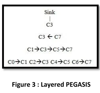
2.1 Layered PEGASIS:
Layered PEGASIS [8] is the extension of PEGASIS. It mainly solves the problem of whose delay is too much in data transmission caused by long chain. In order to avoid node conflicts and data interference, the protocol uses two methods:
Combination of signal coding only a part of the nodes is allowed to transmit data in the same time. The node constructs the layered transmission node tree, select an upper story node to communicate in each layer to achieve parallel transmission of data and reduce delay.
For example C3 is the cluster head selected in the chain, it will integrate and transmit all the data to sink node. So it is the top level, number of layers is begin from 0. Transmission, each node sends its information to the right neighbor node. The node who receives the information sends the data to right after integration, when it reaches to second layer, leaving only C3 and C7, the C3 is a cluster head, C7 should send data to C3, finally to the sink node.
Figure 3 : Layered PEGASIS
3. TEEN:
Available Online at www.ijpret.com 1005 cluster head selected, in addition to attempter data through the way of TDMA, two threshold parameters should be broadcasted and that are (i)Hard Threshold and (ii)Soft Threshold.
(i)Hard Threshold: The hard threshold is the minimum of data transmission.
(ii)Soft Threshold: the soft threshold specifies the change range of data detected.
When the node monitor the data exceeding the hard threshold the first time, nodes can send data to the cluster head, and set the data as new hard threshold and save the monitor value sv (sensed value). Then only the monitoring data is greater than the hard threshold and the absolute value of difference with the sv is not less than the soft threshold, nodes can send data and set the new data as new hard threshold.
Figure 4: TEEN
Advantages:
i. The protocol reduces the amount of data transfer by setting soft and hard threshold significantly, which can monitor a number of unexpected events and hot spots.
Disadvantage:
i. The threshold prevent from some data, not suitable for the application of periodic reporting of data.
4. APTEEN:
Available Online at www.ijpret.com 1006 Attributes (A): This is a set of physical parameters which the user is interested in obtaining
data about.
Thresholds: This parameter consists of a hard Threshold (HT) and a soft threshold (ST). HT is a particular value of an attribute beyond which a node can be triggered to transmit data. ST is a small change in the value of an attribute which can trigger a node to transmit data again.
Schedule: This is a TDMA schedule assigning a slot to each node.
Count Time (TC): It is the maximum time period between two successive reports sent by a
node. It can be a multiple of the TDMA schedule length and it accounts for the proactive component.
APTEEN supports three different query types namely:
(i) Historical query, to analyze past data values
(ii) One-time query, to take a snapshot view of the Network
(iii) Persistent queries, to monitor an event for a period of time.
The main features of APTEEN Protocol are:
By sending periodic data, it gives the user a complete picture of the network. It also responds immediately to drastic changes, thus making it responsive to time critical situations.
It offers a flexibility of allowing the user to set the time interval (TC) and the threshold values for the attributes.
Energy consumption can be controlled by the count time and the threshold values.
Available Online at www.ijpret.com 1007
Disadvantages:
i. The additional complexity required to implement the threshold functions and the count time.
D. Comparative Study:
Comparison between LEACH and PEGASIS:
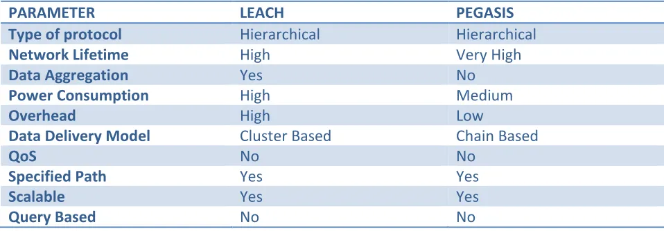
This segment illustrates a theoretical comparison of the two routing protocols – LEACH and PEGASIS. Both the routing protocols fall under hierarchical category, i.e., few nodes are given priority over the others. In LEACH, local data processing occurs at specified nodes called cluster-heads and finally aggregated data is transmitted to the sink node. While in PEGASIS, no data aggregation occurs. LEACH is cluster-based hierarchy while PEGASIS is a chain-based approach. When we check the network lifetime, PEGASIS offers extended lifetime of the network as there is a balance in energy distribution. The number of node deaths in PEGASIS is lesser as compared to LEACH.
Table 1 : Comparison between LEACH and PEGSIS
PARAMETER LEACH PEGASIS
Type of protocol Hierarchical Hierarchical
Network Lifetime High Very High
Data Aggregation Yes No
Power Consumption High Medium
Overhead High Low
Data Delivery Model Cluster Based Chain Based
QoS No No
Specified Path Yes Yes
Scalable Yes Yes
Query Based No No
LEACH ALGORITHM:
STEP 1: Select Cluster Head (CH) randomly
STEP 2: Cluster Formation:
Available Online at www.ijpret.com 1008 Output: Node informtion belonging to cluster
If received ADV from cluster head Then
Begin
If(Node.My_Chid!=null)
Insert into
Node_Info_values (Chid, Hopcnt++)
Reply REP to sender
Send ADV msg to neighbor nodes
Return true
Else
Return false
End
ADV Advertisement message
REP Respond message
CHid Cluster head id
Hopcnt Hop count
Node_Info_value Node information value
STEP 3: Data Transmission
STEP 4: Reselecting cluster head:
Begin
Select value of r based on node energy ranging from 0 to 1
Available Online at www.ijpret.com 1009 If(r<T(n))
Node becomes CH
End
PEGASIS ALGORITHM:
STEP 1: Initialize the network parameters. Determine the number of nodes, initial energy, BS location information. Then chain construction starts.
STEP 2: Create chain using Greedy Algorithm
STEP 3: Create Cluster Head Randomly
STEP 4: Flags are transmitted by Cluster Head to all nodes
STEP 5: End node transmits data to near node
STEP 6: Node that receives data aggregates hat data with its own.
STEP 7: Process continues, finally transmitted to Cluster Head
STEP 8: Finally Cluster Head forwards this aggregated data to the sink.
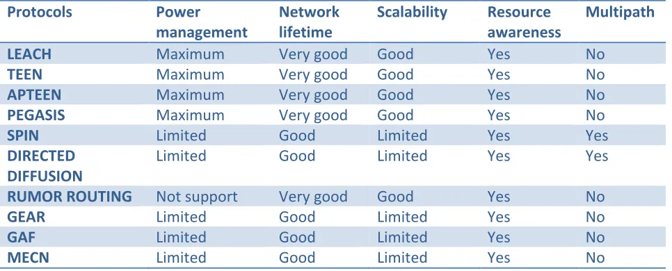
Now we compare the above mentioned routing protocols according to their performance depending on different parameters.
Available Online at www.ijpret.com 1010 In directed diffusion the base station sends queries to sensor nodes by the flooding technique but in SPIN In Directed diffusion each node can communicate with its neighbors, so it does not need the total network information, but SPIN maintains a global network topology. SPIN halves the redundant data in comparison to flooding. SPIN is not suitable for applications that need reliable data delivery as it cannot guarantee delivery of data. SPIN, directed diffusion and rumor routing use meta-data whereas the other protocols don’t use it. Since they are flat routing protocols routes are formed in regions that have data for transmission, but for the others, as they are hierarchical routing methods they form clusters throughout the network.
In case of hierarchical routing energy dissipation is uniform and it can’t be controlled; but in the case of flat routing energy dissipation depends on the traffic pattern. For the previous case data aggregation is done by cluster heads but in the latter case, nodes on multi-hop path aggregates incoming data from neighbors. GEAR limits the number of interests in Directed Diffusion by considering only a certain region rather than sending the interests to the whole network. GEAR thus complements Directed Diffusion and conserves more energy. GAF performs a normal ad hoc routing protocol in terms of latency and packet loss and increases the lifetime of the network by saving energy. Since the sensor networks are application specific, we can’t say a particular protocol is better than others.
Table 2: Comparison Of WSN Protocols
Protocols Power
management
Network lifetime
Scalability Resource
awareness
Multipath
LEACH Maximum Very good Good Yes No
TEEN Maximum Very good Good Yes No
APTEEN Maximum Very good Good Yes No
PEGASIS Maximum Very good Good Yes No
SPIN Limited Good Limited Yes Yes
DIRECTED DIFFUSION
Limited Good Limited Yes Yes
RUMOR ROUTING Not support Very good Good Yes No
GEAR Limited Good Limited Yes No
GAF Limited Good Limited Yes No
Available Online at www.ijpret.com 1011
E. CONCLUSION:
The past few years have witnessed a lot of attention on routing for wireless sensor networks and introduced unique challenges compared to traditional data routing in wired networks. Routing in sensor networks is a new area of research. Since sensor networks are designed for specific applications, designing efficient routing protocols for sensor networks is very important. In our work, first we have gone through a comprehensive survey of routing techniques in wireless sensor networks. depending on the network structure, these are categorized as hierarchical, data centric and location based. In this document we have discussed ten routing protocols and their comprehensive survey These ten protocols are LEACH, TEEN, APTEEN, PEGASIS, SPIN, DD, RR and GEAR, MECN, SMECN. Since the sensors networks are application specific, we can’t say any particular protocol is better than other. We can compare these protocols with respect to some parameters only. Future perspectives of this work are focused towards modifying one of the above routing protocols such that the modified protocol could minimize more energy for the entire system.
REFERENCES
1. D. Estrin, L. Girod, G. Pottie, M. Srivastava, “Instrumenting the world with wireless sensor networks,” In Proceedings of the International Conference on Acoustics, Speech and Signal Processing (ICASSP 2001),Salt Lake City, Utah, May 2001.
2. K. Sohrabi, J. Gao, V. Ailawadhi, and G. J. Pottie, “Protocols for self-organization of a wireless sensor network,” IEEE Personal Communications, Volume: 7 Issue: 5, pp. 16 -27, October 2000.
3. C. Intanagonwiwat, R. Govindan, D. Estrin, Directed diffusion: a scalable and robust communication paradigm for sensor networks, in: Proceedings of the 6th Annual ACM/IEEE International Conference on Mobile Computing and Networking (MobiCom_00), Boston, MA, August 2000.
4. W. Heinzelman, J. Kulik, H. Balakrishnan, Adaptive protocols for information dissemination in wireless sensor networks, in: Proceedings of the 5th Annual ACM/IEEE International Conference on Mobile Computing and Networking (MobiCom_99), Seattle, WA, August 1999.
Available Online at www.ijpret.com 1012
6. Heinzelman W,Chandrakasan A,Balakrishnan H.Energy-efficient Communication Protocol for
Wireless Microsensor Networks[C].In Proceeding of the 33rd Annual Hawaii Int’l Conf.on System Sciences.Maui:IEEE Computer Society,2000:3005-3014.
7. Lindsey S,Raghavendra C.PEGASIS:Power-efficient Gatgering in Sensor Information
Systems[C].In Proceeding of the IEEE Aerospace Conference.Montana: IEEE Aerospace and Electronic System Society,2002:1125-1130.
8. Manjeshwar A, Agrawal D.TEEN: A Protocol for Enhanced Efficiency in Wireless Sensor Networks[C]. In Proceeding of the 1th International Workshop on Parallel and Distributed Computing Issues in Wireless Networks and Mobile Computing’01, 2001: 2009-2015.
9. Manjeshwar A, Agrawal D. APTEEN:A Hybrid Protocol for Effient Routing and
Comprehensive Information Retrieval in Wireless Sensor Networks[C].In Proceeding of the 2nd International Workshop on Parallel and Distributed Computing Issues in Wireless Networks and Mobile Computing’02,2002:195-202.
10. M. Stemm and R. H. Katz, "Measuring and reducing energy consumption of network rfaces in handheld devices", IEICE Transaction on Communications, vol. E80-B, 8, Aug.1997, pp. 1125-1131.