Published online May 29, 2015 (http://www.sciencepublishinggroup.com/j/epes) doi: 10.11648/j.epes.20150404.12
ISSN: 2326-912X (Print); ISSN: 2326-9200 (Online)
Influence of Power Quality Problem on the Performance of
an Induction Motor
Amaize Aigboviosa Peter
1, Ignatius Kema Okakwu
2, Emmanuel Seun Oluwasogo
3,
Akintunde Samson Alayande
4, Abel Ehimen Airoboman
21
Department of Electrical and Information Engineering, College of Engineering, Covenant University, Ota, Nigeria 2
Department of Electrical/Electronics Engineering, University of Benin, Benin City, Nigeria 3
Department of Electrical and Computer Engineering, Kwara State University, Malete, Nigeria 4
Department of Electrical Engineering, Faculty of Engineering and the Built Environment, Tshwane University of Technology, Pretoria, South Africa
Email address:
[email protected] (P. A. Amaize), [email protected] (I. K. Okakwu), [email protected] (E. S. Oluwasogo), [email protected] (A. S. Alayande), [email protected] (A. E. Airoboman)
To cite this article:
Amaize Aigboviosa Peter, Ignatius Kema Okakwu, Emmanuel Seun Olowasogo, Akintunde Samson Alayande, Abel Ehimen Airoboman. Influence of Power Quality Problem on the Performance of an Induction Motor. American Journal of Electrical Power and Energy Systems. Vol. 4, No. 4, 2015, pp. 39-44. doi: 10.11648/j.epes.20150404.12
Abstract:
This paper presents the application of MATLAB® Simulink as a useful tool for predicting the performance of an induction motor. The influence of power quality problem on the performance of an induction motor is critically investigated. Mathematical modelling of an induction motor subjected to an unsymmetrical voltage conditions are presented. The results obtained from the simulation reveal the presence of rotor noise and vibration during operation of induction motor under voltage unbalance.Keywords:
MATLAB® Simulink, Induction Motor, Power Quality, Unsymmetrical Voltage1. Introduction
The widening gap between the power supplied and power demanded is as a result of the increase in the number of domestic, commercial and industrial loads. As such, there has been an increasing stress towards energy management in the industrial sector as they are the major consumers. The continuously varying load demand by domestic consumers has therefore led to a power quality problem. This problem is a major concern to the power system engineers in recent years [1]. Power quality problem or disturbanceis mainly concerned with the deviations of voltage and/or current from the ideal values [2]. Voltage variations and unbalance seem to be the most commonly occurring power quality problems within as a result of unequal distribution loads across the power network [3]. Three-phase induction motors are widely used in industrial, commercial and residential systems whose working performance could be greatly affected when driven with an unsymmetrical three-phase voltages [4], [5]. Industrial utilities make significant amount of investment in order to achieve higher energy efficiency. However, the
lowered performance variations are mainly due to the quality of the incoming supply [6]. Hence, the knowledge of possible variation in performance due to the impact of voltage variation and unbalance is a necessity.
The contributions of this paper are in three folds: To determine the percentage of unbalance voltage that is tolerable for effective operational performance of an induction motor, to determine the impact of the rated voltage, under-voltage and over-voltage unbalance on induction motor operational performance and to simulate the performance of a three-phase induction motor.
This paper investigates the level of difference in the operating performance of induction motors working under balanced and unbalanced voltage conditions. In section 2, mathematical details of the voltage unbalance in the model of induction motors is presented. Section 3 gives the details of the motor parameters used for the study. Section 4 presents the results and discussion obtained from the simulation while the conclusion is given in section 5.
2. Voltage Unbalance Modelling in
Induction Motors
For the sake of simplicity, steady-state performance of three-phase induction motors is usually carried out by neglecting the core loss and friction and windage loss components[7]. However, in industrial situations, the utility energy bill is dependent on components such as the power factor of the plant, total active power usage and overall efficiency of operation. Therefore, accurate estimation of losses is extremely important to avoid significant errors in the efficiency estimation [8]. The core loss depends on the applied voltage while friction and windage loss depends on the operating speed. The power input on no-load is only to account for the no-load losses in the form of stator copper loss, core lossand windage and friction loss.
The modified steady-state per phase equivalent circuit is that takes into account the core loss and friction and windage loss under running conditions is shown in figure 1 [9].
Figure 1. Per-phase equivalent circuit of an induction motor.
where V is the applied voltage, R1 and X1are stator resistance and reactance respectively, R'2 and X'2 are equivalent rotor resistance and reactance as referred to the stator, RCis the core loss resistance, RFWrepresents the resistance of the friction and windage loss, XM is the magnetizing reactance, s is the operating slip, I1 is the stator current, Io is the no-load current component and I'2 is the rotor current referred to stator side.
The equivalent circuit parameters of X1, X'2, XM, RC and RFW can be obtained from the no-load and blocked rotor tests data as presented in reference [9].
By applying symmetrical component technique, under the condition of asymmetry, the per phase induction motor equivalent model can easily be resolved into positive sequence and negative sequence equivalent circuits. Let VRY,
VYB and VBR be the measured line-to-line voltage with VRY
being selected as the reference phasor. For the positive sequence equivalent circuit,
∠ = ∠ ∠ ∠ (1)
∠ = ∠
∅ (2) For negative sequence equivalent circuit,
< = (3)
∠ = ∠
∠∅ (4)
where, VP∠θVP and VN∠θVNare the positive sequence and
negative sequence voltages, I1P∠θCP and I1N∠θCNare the
positive sequence and negative sequence stator
currents,ZP∠θP and ZN∠θNare the positive sequence and
negative sequence input impedances while the operatora is
given by 1∠120°.
Thus, under voltage unbalance conditions, the induction motor can be thought of as two separate motors in operation, one operating with a positive sequence voltage VP and slip 's', and other operating with a negative sequence voltage VN and slip ' (2 - s) ' [7].
The current in each phase can therefore be expressed as
∠ = ∠ + ∠ (5)
∠ = ∠ + ∠ (6)
!∠ != ∠ + ∠ (7)
The actual power output is the sum of the positive and negative power output components given as
"#= " + " (8) where
Positive sequence power output,
" = (%
& ) & ()* )
( *)) (9) Negative sequence power output,
" = (%
& ) & ( *))
( *)) (10) where, I'2P and I'2N are positive and negative sequence rotor current components.
For steady state operation, the torque developed by motor, TM equals the load torque, TL
Tm = TL (11) Under conditions of voltage unbalance, we have
Tm = Tp + Tn (12) where TP and TN denote the positive and negative sequence torque components respectively.
The total power input can be expressed as
"% = +, -.3( ∗ + ∗ )1 (13) where equation (13) indicates the conjugate value.
Motor efficiency is given by
% 3 =
4 × 100% (14) For a qualitative analysis of power quality problem, under-voltage and over-under-voltage unbalance conditions, at the
distribution end and the point of utilization, in three-phase power systems need to be investigated. Some causes of voltage unbalance are the uneven distribution of single-phase
loads in three-phase power systems, asymmetrical
transformer winding impedances, open-Y, open-∆
transformer banks, incomplete transposition of transmission lines, blown fuses on three-phase capacitor banks, etc.[10-17].
Based on the foregoing, performance analysis of equipment in power systems under voltage unbalance condition is very important. Three-phase induction motor is one of the most widely used equipment in industrial, commercial and residential applications for energy conversion purposes. Because of various techno-economic benefits, the three phase induction motors are used more than ever before. However, most of them are connected directly to the electric power distribution system and they are exposed to unbalanced voltages. In theoretical point of view, the unbalanced voltages induce negative sequence current which produces a backward rotating field in addition to the forward rotating field produced by the positive sequence one[18]. The interaction of these fields produces pulsating electromagnetic torque and ripple in speed [19], [20]. Such condition has severe negative effects on the performance of an induction motor.
The effect of voltage unbalance is more pronounced in
three-phase induction motors. When a three-phase induction motor is supplied by an unbalanced system, the resulting line currents show a degree of unbalance that is several times the voltage unbalance.
3. Data Analysis and Simulink
The technical data of a simple three-phase induction motor investigated is presented in table 1.The induction motor is totally enclosed fan cooled (TEFC) with a cast aluminium squirrel cage. The models for the motor under balance and
unbalanced conditions are created using MATLAB®simulink
workspace shown in figure 2. The measured voltage for each line-to-neutral voltage are as follows:
R-N (190V), Y-N (190V) and B-N (194V)
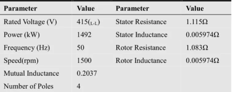
Table 1. Induction motor data.
Parameter Value Parameter Value Rated Voltage (V) 415(L-L) Stator Resistance 1.115Ω
Power (kW) 1492 Stator Inductance 0.005974Ω
Frequency (Hz) 50 Rotor Resistance 1.083Ω
Speed(rpm) 1500 Rotor Inductance 0.005974Ω
Mutual Inductance 0.2037
Number of Poles 4
Figure 2. Simulink model for the balanced and unbalanced conditions.
torque 1.66 stator current 4.479 4.794 rotor speed 1501 rotor current 0.2473 0.002689 Continuous ic2 3.96 ic1 4.794 ic 4.479 Y Voltage Measurement 4 v + -Voltage Measurement 3 v + -Voltage Measurement 1 v + -Vb1 296.2 Va2 766.9 -753 Va1 286.4 Va 291.9 RPM -K-RMS7 signalrms RMS6 signalrms RMS5 signalrms RMS4 signalrms RMS3 signalrms RMS2 signalrms RMS1 signalrms RMS signalrms R Induction Motor Tm m A B C Current Measurement 4 i + -Current Measurement 2 i + -Current Measurement 1 i + - Constant2 0 B Active & Reactive
Power V I PQ 6 5 4 3 2 1 <Rotor speed (wm)> <signal1> <signal2> <Electromagnetic torque Te (N*m)> <Electromagnetic torque Te (N*m)> <signal3>
The influence of unbalanced voltage on its performance is evaluated under rated conditions with balanced voltage at no-load. The motor is tested with three types of three-phase voltage unbalance factors which are the rated, under-voltage and over-voltage factors as shown in table 2.
Table 2. Voltage unbalance factors.
1.05 Over-Voltage Unbalance 1.00 Rated Voltage Unbalance 0.95 Under-Voltage Unbalance
For the analysis of the under-voltage unbalanced condition, the positive sequence voltage is fixed at 95% of the rated voltage and the simulation performed for different values of VUFs (Voltage unbalance factors) between 2% and 10%. For the case of the ratedvoltage unbalanced condition, the positive sequence voltage was fixed at the rated voltage and simulation conducted for different grades of VUF from 2% to 10%. Finally, the over-voltage unbalanced condition is studied with the positive sequence voltage fixed at 105% of the rated voltage and simulation performed for different values of VUFs.
4. Results and Discussion
The simulation results obtained from the analysis of the induction motor under balanced and unbalanced conditions are presented graphically in time domain.
4.1. Balanced Voltage
Figure 3. Rotor currents on no load balanced voltage.
Figure 4. Rotor currents on full load balanced voltage.
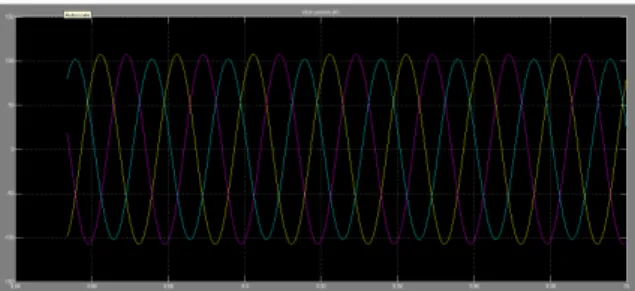
The three-phase stator currents waveforms shown in
figures 3 and 4 are steady and the induced rotor current waveforms are uniform and linear as seen in figures 5 and 6. The Induced rotor currents on no-load and on full load are found to be 0.5A and 15A respectively while stator currents are 3.5A and 17A on no-load and full load respectively.
Figure 5. Stator currents on no load balanced voltage.
Figure 6. Stator currents on full load balanced voltage.
4.2. Unbalanced Voltage
4.2.1. Voltage Unbalance – Under-Voltage
Figures 7, 8 and 9 show the waveforms produced under unbalanced voltage conditions.The waveforms indicate rippled and cloudy stator and rotor currents on full load at under voltage unbalanced conditions. Rotor current are above indeterminate with average value of 23A and 18A on 75%, and 50% of load respectively. While the stator currents are indeterminate with average value of 25A and 20A on 75% and 50% of full load respectively.
Figure 7. Rotor currents on full load at under-voltage unbalance.
At under-voltage unbalance condition, for all values of VUF, the motor’s torque and speed were undefined for full load operation as shown in figure 9. However, at reduced loads, the outputs were determinate with indications of growing gross ripples as the value of VUF increases.
Figure 9. Electromagnetic torque and rotor speed at full load torque at under voltage unbalance (VUF of 2-10% with positive sequence voltage fixed at 0.95 of rated voltage).
4.2.2. Voltage Unbalance – Over-Voltage
The waveforms of the rotor and stator currents at full load over-voltage unbalance condition are presented in figures 10 and 11 respectively. The estimated values of rotor current are 25A, 18A and 12A on full load, 75% and 50% of full load respectively. Stator currents are also estimated to be 28A, 20A and 14A on 75% and 50% of full load respectively.
Figure 10. Rotor current at full load over-voltage unbalance.
Figure 11. Stator current at full load over voltage unbalance.
4.2.3. Voltage Unbalance – Rated Voltage
The waveforms indicated rippled and cloudy stator and rotor currents on full load at rated voltage unbalanced conditions as shown in figures 12 and 13 respectively. Rotor current are indeterminate, 20A, 13A on full load, 75%, and 50% of load respectively. Stator currents are indeterminate, 22A, and 15A on full load, 75%, and 50% of load respectively.
Figure 12. Stator currents at full load rated voltage unbalance.
Figure 13. Rotor currents at full load rated voltage unbalance.
5. Conclusion
This paper has shown that the presence of ripples in both stator and rotor currents’ waveforms, in all cases of unbalance voltages when motor is on load, indicate the presence of harmonics. The simulation results also showthat more current is drawn by the stator and more is induced in the rotor as the load increases in all cases of unbalance. This implies that increase in copper losses accompany voltage unbalance, which may lead to increase heating, horsepower load and thus a reduced rated output power.
At over-voltage unbalance however, motor indicated fair performance at VUF of 2-4% with a load reduction of 50%. At rated voltage unbalance with VUF of 2-4%, good performance was observed on load reduction of 50%. Above VUF of 4% for all types of unbalance, motor operation became grossly inefficient and load reduction did improve operational performance of the induction motor.
From the findings of this paper, it has shown that there is a noteworthy difference in the performance of an induction motor under unbalanced source voltages compared to balanced source voltages. The results proved that the operational performance of an induction motor can be studied
using simulated result from MATLAB® Simulink without
going through the arduous analytical method. Since unbalanced conditions cannot be completely eradicated, it is therefore essential that motors be protected against all types of unbalances with NEMA, IEC and IEEE specifications and appropriately derated for effective and efficient performance.
References
[1] Ezer, D., Hanna, R. A. and Penny, J. (2002). “Active Voltage Correction for Industrial Plants”, IEEE Trans. Industry Applications. 38(6), pp1641-1646.
[2] Bollen, M. H. J. (2000). “Understanding Power Quality Problems,” IEEE Press, New York.
[3] Jouanne, A. and Banerjee, B. (2001). “Assessment of Voltage Unbalance”, IEEE Trans. Power Delivery 16, pp 782-790. [4] Jouanne .A. and Banerjee, B. October 2001 “Assessment of
Voltage Unbalance,” IEEE Transactions on Power Delivery, Vol. 16, No. 4, pp. 782-790.
[5] Kersting, W. H. (2001) “Causes and Effects of Unbalanced Voltages Serving an Induction Motor,” IEEE Transactions on Industry Applications, Vol. 37, No. 1, pp. 165-170.
[6] De Almeida, A.T., Ferreira, F.J.T.E., Both, D., (2005). “Technical and Economical Considerations in the Application of Variable-Speed Drives with Electric Motor Systems.” IEEE Transactions on Industry Applications 41, pp. 188–199. [7] Johan, A. (2011). “Investigation of Issues Related to Electrical
Efficiency Improvements of Pump and Fan Drives in Buildings.” Thesis for the Degree of Doctor of Philosophy, Department of Energy and Environment, Chalmers University of Technology Goteborg, Sweden
[8] Wang, Y. J. (2001). “Analysis of Effects of Three-Phase Voltage Unbalance on Induction Motor with Emphasis on the Angle of the Complex Voltage Unbalance Factor.” IEEE Trans. Energy Conversion 16(3), pp 270–275.
[9] Ibiary, Y. (2003). “An Accurate Low-Cost Method for Determining Electric Motors Efficiency for the Purpose of Plant Energy Management. IEEE Trans. Industry Applications 39(4), pp 1205-1210.
[10] Kothari, D. P. and Nagrath, I. J. (2004). Electric Machines, 3rd Edition, Tata McGraw Hill, New Delhi, India.
[11] Annette, J. and Banerjee, B. B, May 2000 “Voltage Unbalance: Power Quality Issues, Related Standards and Mitigation Techniques,” Electric Power Research Institute, Palo Alto, CA, EPRI Final Rep..
[12] Woll, B.J, January/February 1975 “Effect Of Unbalanced Voltage on The Operation of Polyphase Induction Motors,” IEEE Trans. Industry Applications, vol. IA-11, No. 1, pp. 38 [13] Schmitz, N. L and Berndt, M. M, February 1963. “Derating
Polyphase Induction Motors Operated with Unbalanced Line Voltages,” IEEE Trans. Power App. Syst., pp. 680–686 [14] Williams, J. W, April 1954. “Operation of 3-phase induction
motors on unbalanced voltages,” AIEE Trans. Power App. Syst., Vol. PAS-73, pp. 125–133.
[15] Seematter, S. C and Richards, E. F, Sept./Oct. 1976. “Computer Analysis of 3-Phase Induction Motor Operation Of Rural Open Delta Distribution Systems,” IEEE Trans. Ind. Appl., Vol. IA-12, pp. 479–486.
[16] Muljadi, .E, Schiferl, R. and Lipo, T. A, May/June 1985. “Induction Machine Phase Balancing by Unsymmetrical Thyristor Voltage Control,” IEEE Trans. Industry Applications, Vol. IA-21, No. 4, pp. 669–678.
[17] Lee, C. Y, June 1999 “Effects of Unbalanced Voltage on the Operation Performance of A Three-Phase Induction Motor,” IEEE Trans. Energy Conversion, Vol. 14, No. 2, pp. 202–208. [18] Smith, D. R, Braunstein, H. R, and Borst, J.D, April 1988.
“Voltage Unbalance In 3 and 4-Wire Delta Secondary Systems,” IEEE Trans. Power. Delivery, Vol. 3, No. 2, pp. 733–741.
[19] Krause P.C, 1986. Analysis of Electric Machinery, McGraw- Hill, 1986, New York.
[20] Alwash, J. H. H., Ikhwan, S.H., March 1995. “Generalised Approach to the Analysis of Asymmetrical Three-Phase Induction Motors”, IEE Proceedings Electric Power Applications, Volume: 142, Issue: 2, Page(s): pp87-96.