Application of Product Data Management Technologies for Enterprise
Integration
Dr J X Gao*, Mr Hayder Aziz Department of Enterprise Integration, School of Industrial and Manufacturing Science, Cranfield University, Bedford, MK43 0AL, United Kingdom
Telephone: +44 (0)1234 754073 Fax: +44 (0)1234 750852 Email:[email protected]
And
Prof P G Maropoulos, W M Cheung School of Engineering, University of Durham, South Road, Durham, DH1 3LE, United Kingdom
Telephone: +44 (0)191 3742574 Fax: +44 (0)191 3742546 Email:[email protected]
* Contact person
Abstract
Product Data Management (PDM) systems and their offspring Collaborative Product Development and Product Lifecycle Management technologies aim to bring the engineering enterprises together, allowing seamless interoperability between different departments and throughout the extended enterprises. However, there are a number of shortcomings in the current crop of commercially available systems such as the lack of design knowledge sharing, links with Enterprise Resource Planning systems, knowledge management tools and a generic standard for PDM system implementation. This paper presents a proposed software solution to some of the above problems. In particular, the paper describes methodologies being developed aiming at overcoming the lack of analysable product information at the conceptual stage of product design and manufacturing evaluation, along with the integration of such a concept design tool within a distributed environment. A leading PDM system is used to manage all the information and knowledge which is made available to internet/intranet users in a controlled manner. International Standard for Exchange of Product Data Model (STEP) is being implemented to enable the integration of the design environment with manufacturing and enterprise resource management systems. In addition, the paper also introduces three other recent/on-going projects carried out at Cranfield University in the application of PDM, knowledge management and STEP standard for integrated manufacturing business.
1 INTRODUCTION
Product Data Management (PDM) systems have been widely used in industry now after significant research and development effort made over a decade. However, the primary applications of these tools so far have been limited to the engineering side of the enterprise, although PDM systems are designed for and capable of managing enterprise-wide information especially with the latest Web-based technologies (Yen, D.C, 2002). Bi-directional communications with ERP, manufacturing planning and Customer Relation Management (CRM) systems consist of very simple interfaces and data exchange with no real-time interoperability
between the different functions of the enterprise. In addition, the theme of the extended PDM, that is Collaborative Product Development or Product Lifecycle Management, still lacks the essential “development” aspects and acts simply as a gateway for sharing designs, documents and effect revision control, engineering change and workflow. Knowledge management capability especially those for conceptual design stage is absent in the commercial PDM systems. This is however advancing at a rapid pace in the current commercial arena. This paper gives an overview of the current trend in PDM systems development and their applications within the extended enterprise, and introduces the methodologies being developed in an on-going research project sponsored by the Engineering and Physical Science Research Council (EPSRC) which aims to develop PDM technologies further to remedy some of the current shortcomings. Three other related projects carried out at Cranfield University are also described.
1.1 PDM Technologies in Enterprise
There is a wide variation in the functionalities offered by PDM systems depending on the requirements of the target markets. At the basic level (or ‘low end’) a PDM system provides simple data storage, document management, revision/change/access control, project and workflow management, and simple interfaces with other systems (see website: www.pdmic.com). There is no direct interface to ERP, Customer Relation Management (CRM) or manufacturing planning systems and it generally uses a less complicated database which doesn’t offer such advanced functionality as concurrent view/modification of data, data replication and scalability offered by the ‘high end’ solutions. They also generally lack direct interface with CAD systems, or offer a very simplified connection with data check-in and check-out functionalities. These low end PDM systems are more suitable for small and medium enterprises (SMEs) that only need a single server and have less complex relationships with a supply chain. The high end systems are more sophisticated with customisable and scalable solutions which offer enterprises the ability to connect distributed design and manufacturing sites together to work collaboratively on product development and also allow the supply chain and customers to be involved and access / modify data during the project’s lifecycle. High end PDM systems offer a number of different methods for
either connecting to or offering ERP functionality. Some systems, such as PTC’s Windchill used in this project (see Website: www.ptc.com), offer a connection gateway through a proprietary application layer within the application (in this case Info*Engine) and through this gateway any external application has bi-directional access to data stored in a Windchill repository in real time. However even such connectivity contradicts the ERP philosophy of storing all the data of the enterprise in a single repository.
The next route taken by vendors is to supply specific ‘plug-in’s for different ERP systems. This has achieved a certain level of interoperability. However, the systems were still separated at the core logic and data level. Even if they can, in theory, share the same database, vendors generally shy away from it. On highly customisable solutions such as Enovia from IBM Dassault (see Website: www.enovia.com) and Metaphase from SDRC (see Website:
www.sdrc.com/metaphase/). it is possible to integrate the data and logic / rules of the PDM system with the enterprise system via major and costly customisation. But the real problem is the definition and standardisation of the data/knowledge to be exchanged, and this has not been solved. The product data generated during an engineering project would be useful in an ERP environment to help plan the resources necessary for the successful realisation of the project. Traditionally, data transfer and co-operation between the “technical” and “non-technical” divisions of enterprises has been lacking. Today companies have to operate in a concurrent engineering environment, and this in turn entails multi-disciplinary work teams and sharing of the project development data at every stage. To enable this, engineers have to use the functionality of ERP systems to assess resource availability as well as enable marketing personnel and accounts to direct access the project in a product oriented view. The links between the “technical” and “non-technical” parts of the enterprise can be made using either the ERP system or the PDM system, although inevitably, the two separate systems, one product oriented and the other resource oriented, will remain.
The original PDM paradigm has been extended to encompass the supply chain of the enterprise within the framework of its internal product development processes, and many of the PDM vendors are including functionality to enable customers to access selected data from the PDM portal. This extended PDM is referred to as Collaborative Product Development (CPD) or Product Lifecycle Management (PLM) system (see Website: www.ptc.com). This category of products improved the ability of enterprises in effective supply chain management and collaboration concurrently on product development between separate offices and also with the sub-contractors. CPD systems, however, do have many of the shortcomings. The software is still only a “portal” for storing data and managing projects. The next step in the evolutionary development will be the concurrent and collaborative design of products online. It was reported that (Greco 2001) Alibre, 3G Corporation and ImpactXoft have solutions that enable online collaborative design using solid modelling tools. CPAD (Shyamsundar and Gadh, R., 2001) and Syco3D (Nam and Wright 2001) are experimental tools to allow the generation of geometry as well as the classification of assemblies and parts into libraries for re-use. However there is no provision in these systems to enable collaborative working in real-time, or to generate STEP compatible outputs for later processing.
1.3 PDM and the STEP Standard
PDM vendors use their own proprietary standards to define the product data within their own systems, although many do output XML format data (see Young 2000 about XML). This non-standardised format increases the cost of customisation needed to transfer information between different vendors’ software products. The STEP PDM schema (ISO 1999) is a subset of a number of STEP Application Protocols (APs). It contains many, but not all, the requirements of PDM systems. It contains functionality for both parts and documents (identification, versioning, structures, approvals, authorisation, project, work order, requests, effectiveness, classification and properties). The STEP PDM schemas offer vendors the ability to standardise the functionality, using common nomenclature for much of the functionality of PDM systems, whilst allowing them to extend the functionality using either EXPRESS schemas, or other programming
tools. The PDM schemas are generic in nature and can be applied to most electro/mechanical applications with ease, and can also ensure ease of access to the part information from the Industry standard STEP-based Boundary Representation (B-Rep) models.
There are other models for PDM interoperability (Oh 2001) being developed using UML to map the data between generic CAD and PDM systems. However, this does not provide the same level of support or acceptance as ISO standard-based schemas such as the PDM-Schemas. The widespread adoption of PDM Schemas would herald new levels of interoperability between enterprise level systems with very little customisation. It also opens up the possibility of streamlining many applications that feed data into PDM/ERP systems through the use of STEP native product models and data. This project has been initiated to explore the possibilities of applying STEP technologies for production applications and to drive collaborative and concurrent engineering design.
1.4 PDM and Knowledge Tools
Generally commercial PDM systems lack knowledge management capabilities. There are research prototype tools which aim to integrate Artificial Intelligence (AI) into PDM systems such as the Distributed Open Intelligent PDM System developed by Kim et al (Kim 2001). The philosophy behind this particular PDM implementation is the use of open-standard tools and file formats. The PDM system includes most software tools available in other PDM applications such as PTC Windchill. There are a number of unique features in this implementation. The use of intelligent agents to perform many of the PDM tasks and Knowledge Query and Manipulation Language for queries sets it apart from other PDM implementations. The PDM software consists of a dynamic and flexible workflow model, as opposed to the rigid workflows seen in many commercial PDM applications. This greatly enhanced the flexibility and therefore usability of the system in a real-world situation. In addition, the program is designed from the outset for the use of STEP based model files to store and distribute product information. STEP Data Access Interface is used for content searching of Product data. However, no mention was made about which
Application Protocol of STEP they intended to use. The research project carried out at Cranfield University in integrating PDM with knowledge tools will be described later in this paper.
2 THE METHODOLOGIES BEING DEVELOPED
The project is mainly devoted to the key issues of supporting the concurrent and multi-disciplinary product development process in a collaborative and distributed environment. The conceptual design phase of new product development is deemed to be the area where large savings in time and cost can be made by integrating the engineering, manufacturing and resource planning facets of the enterprise. Therefore the focus is on the development of a conceptual design environment with new tools, knowledge and integration methodologies. The software items used as the basis of the project included a mixture of commercial and academic developments. On the commercial side PTC's Windchill CPD application is used. This application server is written in Java2 and uses an Oracle 8i database. Service to clients is through a Web browser and this is enabled via Apache Web server and the Tomcat Servlet engine. The functionality that Windchill doesn’t include as standard is provided and integrated during this project.
2.1 Integration of PDM and Expert System
First, a generic expert system development tool based on the RETE algorithm - Protégé-2000 is included. It has been developed by Stanford University and written in Java2 (Stanford University, 2002). The whole package includes an automatically generated forms based user interface for any expert system that is defined within Protégé. In addition, the program has the ability to store the knowledge base in many different formats, such as CLIPS (Giarratano 2000), XML, Resource Description Format (RDF) and through a Java Database Connectivity interface straight to a database. Resource Description Format is found to be the most advantageous format for the knowledge base. The knowledge in the knowledge base is defined as text (Rogers 1998). The program can be packaged into a single Java Archive and distributed as an applet to Windchill clients during runtime. In order to define rules within Protégé the Java Expert System Shell
(JESS) was added as a plug-in. This enables standard CLIPS rules to be added to the knowledge base.
The primary aim of this knowledge base is to enable the conceptual product development system to manage knowledge in a more intelligent way rather than simply document management environment. It also enables the project co-ordinator to specify the ontology within their knowledge base thereby standardising the nomenclature and vocabulary used by all persons entering or modifying project information. There are already some implementations of rule-based expert systems to aid in the definition of designs using lifecycle information as ‘features (Esterline 1993, Zhang 2002). These however, like CADET (Rogers 1998), do not include feature geometry or machining features. The solution proposed in this paper may sound inflexible but the Protégé-2000 Expert System editor enables very intuitive and graphical user interface based control of the underlying ontology of the knowledge base. This also means that information such as customer requirements and concept design specifications can be managed more efficiently and yet allow the PDM project managers to tailor the ontology for each project separately.
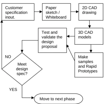
The project data is stored in standard Windchill cabinets and, using Windchill’s data manager; model information can be translated on the fly from most CAD formats to STEP part 21 files. Processes for entering knowledge into the knowledge base can be included as part of the workflow and persons delegated tasks for entering particular data. In this project a specific ontology was developed taking as an example an automotive supply company. This is an ideal example as the company operates over many different sites, and has very close links both to OEMs (its customers) and to specialised manufacturing firms (its supply chain). Figure 1 shows the simplified design process of the collaborating company.
Figure 1: The Simplified Product Design Process of the Collaborating Company
The customer requirements are classified into classes and slots within Protégé and a small-scale knowledge base about a long term project for an OEM is built. The customer requirement knowledge is a particularly important area for the Tier-1 supplier to investigate as dealing with many different OEMs who use different vocabularies to describe essentially the same specifications. Often this confuses the engineering teams who try to draw up the concept design specifications, generate quotations, estimate resource needs and the practicality of the customer’s requests. During this phase of the project it is very important to link together the items of information essential for the accurate estimation of:
• Best design concepts/configurations;
• Likely cost of items based on historical data from earlier projects with similar configurations;
• Likely time-frame for developing/producing the items and estimating the necessary resources to be allocated; and
• Generating conceptual BoM and process plans for early analysis of best concepts intended for design for manufacture and assembly.
YES NO Customer specification input. Paper sketch / Whiteboard 2D CAD drawing 3D CAD models Make samples and Rapid Prototypes Test and validate the design proposal Meet design spec?
The personnel involved in conceptual design must have easy access to historical conceptual design information from previous projects to learn from earlier experience, and access to resource planning and accounting data in a project oriented view that allows them to estimate likely costs, benefits, manufacturing and resource issues.
2.2 Integration of PDM with Manufacturing Planning
The process planning system to be integrated is CAPABLE developed by Durham University as a rough cut process and resource planning tool for conceptual design (Maropoulos 1998). It is also written in Java2 and uses an Oracle 8i database. The system generates plans from non-geometric feature models defined as Java classes. In this project, the STEP AP-224 (SCRA 2001) machining features definition for process planning application protocol is used as the basis for the feature models to be integrated and analysed, as it will be seen later. AP-224 is also used to generate and store feature-complete solid models for conceptual designs. The second application used is a commercial process planning tool LOCAM provided by LSC Group. It is the first application that can take a STEP AP-224 part-21 file as input and automatically generate a process plan from it. This however depends on the creation of the manufacturing rules database. The LOCAM program will be used to generate process plans in real-time as the model is being created to enable the designers to intuitively make changes and assess the design from the conceptual stage. This program is packaged as an ActiveX Dynamically Loaded Libraries (DLLs’) and will be integrated with the AP-224 modeller in a unified user interface.
2.3 Integration of PDM with ERP
The integration with ERP system enables the project team to interact with accounting and material resource planning functions of the enterprise to optimise the design from the earliest phase. Integrating with the supply chain in cases of companies where significant amount of work is sub-contracted reduces the amount of time and money spent on engineering change. The
integration will primarily be between CAPABLE and Windchill with the ERP system SAP/R3, through Windchill’s Info*Engine access layer, which provides the resource and manufacturing information. This enables relevant resource information to be displayed as part of the Windchill project vault. However, in order to access information from the ERP system the team have to construct a program that can send queries to retrieve the correct information from SAP and also to construct process plans in order to analyse its manufacturability. It is also planned to integrate the PDM system with ERP system PICS in the later stage which is implemented in one of the collaborating companies.
2.4 The PDM-based Conceptual Design Environment
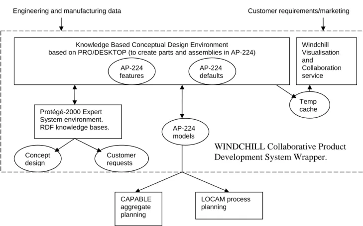
In order to create the process plans and feed data into the PDM systems a conceptual design environment that is easy to use and integrate with the other components of the system is needed. Figure 2 shows the relationship of the tools within the design environment being developed.
Figure 2: Schematic Diagram of the Conceptual Design System
Knowledge Based Conceptual Design Environment
based on PRO/DESKTOP (to create parts and assemblies in AP-224)
Windchill Visualisation and Collaboration service Protégé-2000 Expert System environment. RDF knowledge bases. Temp cache Concept design Customer requests
WINDCHILL Collaborative Product
Development System Wrapper.
AP-224 features AP-224 models AP-224 defaults
Engineering and manufacturing data Customer requirements/marketing
LOCAM process planning CAPABLE
aggregate planning
The Pro/Desktop 2001 solid modeller from PTC was chosen for a number of reasons, i.e., • The software can be distributed over the Windchill system to clients;
• ActiveX Dynamically Loaded Libraries (DLL) and Visual Basic for Applications macros can be integrated;
• It supports most of the features of 3D CAD tools (In fact it uses the same kernel, Granite1, as Pro/Engineer 2001);
• Feature primitives can be defined for drag-and-drop functionality, enabling the construction of AP-224 feature models with ease; and
• Integration with Windchill is possible through PTC’s Pro/Intralink interface.
The software is modified to output AP-224 files to enable other applications to process it and to generate process and resource plans. The AP-224 file generation is done in two steps. First, the feature geometry is generated using the 16 base machining features of AP-224. Then, the remainder of the information is entered using forms. Where possible, default values are supplied for the forms to reduce the amount of form filling necessary to make the AP-224 files. LOCAM is also integrated through ActiveX DLL which allows the generation of process plans during the concept model creation process, optimisation of the design for manufacturing and assembly from the first phases of design.
The output from this phase enables applications such as CAPABLE to generate generic process and resource plans and to supply data to ERP systems. The model data can be entered into the vault within the PDM system and the LOCAM generated process plans stored alongside in an XML file. Collaboration is possible using the Visualisation services within Windchill. The data generated by the Expert System, Process Planning and the AP-224 models can all be stored in an XML file within the Windchill system.
Three major projects and a number of smaller projects have been/are being carried out at Cranfield University aiming at integrating different enterprise applications through PDM technologies. The three major projects are briefly described below.
3.1 Teaching Company Scheme with Design Rule
A Teaching Company Scheme (TCS) with Design Rule Ltd. (Ref:3284) aimed to develop a knowledge based design system within a PDM system (in this case SmarTeam). The aim is to provide designers with graphical tools which allow designers to implement and manage knowledge easily without the need for a 'middle man' (normally an IT specialist). The system breaks down into five main functional categories, i.e., Knowledge Management, Knowledge Acquisition, Evaluation of Knowledge, Application of Knowledge and Knowledge Monitor and Interface. The system is based almost entirely on Windows® technologies. The main reason for this is that it allows the use of some of the most up to date and industry standard computer technologies, including: ActiveX, which is the main method of communication between the various modules on a single machine; COM (Component Object Model), DCOM (Distribute COM) API (Application Programming Interface), which allows access to the open architecture of SmarTeam making it possible to use and control any of the PDM functions. Its is with this COM API open architecture that SmarTeam can carry out all the communications from machine to machine, from client to server, allowing the very best internet transfer technology and giving truly global ramifications for the Intelligent PDM system.
The implementation will be completed through three stages. Stage one involves integrating an inference engine into the PDM along with a GUI to build, manage and store the knowledge base. The system will allow users to build knowledge bases that directly interact with PDM data objects. It also contributes to the overall goal of the system by forming the initial GUI and the input method for the decision-making logic (see figure 3). Stage two builds on the previous by including functions that allow users to interact more deeply with the CAD package CATIA. This will allow the developers to have full advantage of the geometric engine and analysis tools, while being
able to apply the decision making logic of the KBS system and utilize the information stored in the PDM database. With this stage complete it will provide the company with a full knowledge based design solution. Stage three should provide an environment that allows users to model graphically the process they employ when applying their knowledge, including the decision-making logic along with the actions that carry out the tasks. The stage involves implementing a system that can interpret, use and duplicate the code produced for action across a wide variety of applications integrated in the PDM. Once that is done it is a question of creating the action blocks themselves. This will be an ongoing process for the life of the product, but enough basic action blocks should be create at the beginning to allow user to start building knowledge process flows.
Figure 3: The PDM Object Based Graphical Rule Builder Developed by TCS Project
The current stage of the project is drawing towards the end of stage one. Users now have the ability to create rules graphically based on the object definitions (classes) contained within a SmarTeam PDM database using simple drag and drop techniques, removing the requirement for the user to go anywhere near any programming code. The rules can then be uploaded and
managed within SmarTeam from anywhere in the enterprise. The Haley Enterprises rule-based server carries out evaluation of the PDM data based on the uploaded rules using the communication set up between the two server applications and the users can monitor the results on client machines using the SmartDesign mini helper. The system offers a new platform for users to create effective KBS applications from simple event notification to a full-blown smart product configuration system. The PDM base brings life cycle control, enterprise wide distribution and easy visibility to all KBS facts and rules. It is in essence effective data management for KBS on a scale as yet unseen in KBS technologies.
3.2 EPSRC Project in PDM Based Assembly Planning
This project has developed new methodologies for Computer-Aided Assembly Process Planning (CAAPP). This was done primarily by the integration of CAAPP functionality with a PDM tool (Motiva) providing a data control framework and a high-level data structure to form the basis of planning. This project utilised the Motiva DesignGroup, a mid-range, Windows-based PDM system to provide a data control framework on which the CAAPP system is based. The DesignGroup development kit consists of various ActiveX controls and type libraries that give developers access to the majority of the system’s resources. This type of component-based integration provides a quick and effective method of providing engineering software with high quality data with as little coding as possible. Integration of CAAPP and PDM provides various methods to simplify the retrieval of relevant data, dramatically cutting down this wasted time.
MAPS CAAPP System Motiva DesignGroup PDM System: Product Modelling Data Handling Document Management Spatial Technology BuildingBlox: Solid Modelling Feature Extraction Constraint Extraction Lassalle Technology AddFlow: Structure Modelling Sequence Rep. CLIPS Expert System: Process Selection Feature Recognition Visual Basic: Integration Object Modelling Data Configuration
Figure 4: The Tools Used in the PDM based Assembly Planning System
As seen in figure 4, the system was implemented in Visual Basic and C, running under the Windows NT operating system. Motiva DesignGroup PDM System was used to handle product data and related documents. It interacts with Spatial Technology Building Blox (ACIS) to generate solid models for products and extract feature and constraint information as needed. The Lassalle Technology AddFlow software is used to construct liaison graphs both manually and automatically by the algorithms developed or rules in the CLIPS expert system. In using the system, an assembly structure is often represented by a simple graph. The system uses this technique to both display a structure definition and allow interaction with the underlying object-oriented representation of the assembly. The liaison graph is of a typical form, i.e., a component is represented by a circular node and an arc linking two nodes represents a liaison between two components. Fasteners are represented by a square node, midway along a rigid arc. The diagramming component AddFlow is used to provide a dynamic method of representing an assembly structure. AddFlow provides creation, modification and analysis techniques for various types of diagram and was found to be an excellent solution to the problem of generating liaison graphs. The assembly structure can be altered through interaction with the liaison graph; adding (or deleting) nodes, links and fastener details immediately updates the object-oriented model used to represent an assembly. To facilitate rule-based reasoning, the CLIPS expert system is embedded in the system. This allows the system to process rule files and retrieve the results. Getting and setting CLIPS variables and controlling expert processes is facilitated by an external Dynamic Link Library (DLL), containing CLIPS user-defined functions and the code to initialise, run and return results from a knowledge-base. For more details and case studies of this project refer to Gao and Bowland (2002).
3.3 STEP Based Process Planning
This research project was sponsored by a leading consultant company LSC Group, aiming at the development of a new generation process planning system using the latest tools and technologies, and to fully comply with STEP AP224 for process planning using machining
features. Although AP224 has been accepted as an international standard, there is a surprising lack of compatible software packages in the market. The developed prototype STEP-enabled Manufacturing Planning System (SMPS) can generate process plans and associated documents from AP224 files automatically, without any user interaction. The system consists of decision logic stored in an external database that makes it generic and compatible with any manufacturing application. A graphical tool is provided for knowledge capture. The system can also accept a feature tree generated using the Feature Model Editor (FME) which has been developed as an ‘add-on’ to the system. FME is intended to be a tool for conceptual design of simple components, and to be integrated with PDM systems. FME feature tree is used in the early design stage while the AP224 file generated from detailed design model is used in the later stages. The prototype system is intended for single piece machined (prismatic) parts and has been tested with case studies provided by the project collaborators (Sharma 2002).
The overall flow of the application is shown in figure 5 as a block diagram. The physical disk files and applications are clearly marked in the diagram. Each application needs to make a distinct boundary between the application itself and the data it uses. In this system, the Data Access Layer (DAL) has been compiled as a separate ActiveX Dynamic Link Library (DLL). This DLL exposes a single class, which provides the necessary methods and properties for all the bi-directional data access requirements of the program using standard Sequenced Query Language (SQL) calls. Making the appropriate changes to the DAL can easily accommodate any changes to the database schema. If binary compatibility is maintained with the older version, the main system using this DAL needs not be recompiled. All external file access is done using the data access layer.
The AP224 viewer/reader is an application for reading and viewing AP224 files. The application is capable of reading the AP224 file and displaying the solid model as well as displaying the feature tree of the component including all the attributes of the features. The feature can also be selected from the drop-down list in the toolbar. The STEP files are plain ASCII text files. These files are read into the viewer and displayed using ST-Developer from StepTools Inc., which is a set of Computer-Aided Software Engineering (CASE) tools that reduce the effort required in implementing STEP applications. An important component of ST-Developer is the ROSE C++ library. This library makes it possible for application programs to read, write, create, and
Figure 5: The Information Flow of the STEP Based Process Planning System Logic Engine Logic Database Logic Designer AP 224 STEP File Configuration Files/ ROSE Library Intermediate File
Post-processor Resource Manager
Manufacturing Database
Document Generator/ Viewer
Crystal Report Tempelates/ XML Stylesheets Output Plan Database FINISHED PLAN (*.XML) Disk File Program Database FINISHED PLAN (*.RTF) NC Code AP224 Viewer FME Part File CLIPS
manipulate STEP digital product information. This library has been used to develop the AP224 functionality of the system.
The analytical logic, or more specifically the domain and empirical knowledge, is kept in an external database. This logic can be edited and viewed graphically as a flowchart using the Logic Designer. The user also has the options of having multiple nested logic flowcharts. The point of entry into the logic, or the starting flowchart can be selected/ configured by the user. This is very convenient in case the same system is to be used for different domains.
The manufacturing database editor allows the user to edit and maintain the resources data and other tables in the database. The manufacturing database editor can be accessed as a standalone application or accessed from within the Logic Designer for easier navigation. Various types of resource tables are provided to hold data such as standard questions, explanation and help lines, operation macros and standard texts. It is also used to store the CLIPS rules.
The logic engine is the heart of the system, responsible for actually running the logic stored in the logic database. The logic engine also processes and executes any calls to the CLIPS expert system. The logic engine uses the functionality of the AP224 viewer/reader to open AP224 file and generate a feature tree of the component in the memory. This feature tree is loaded into an internal memory data structure and can be interrogated by using the appropriate flowchart commands. For example, the developer could write a logic to load a AP 224 feature tree in the memory and then write a recursive loop to interrogate the features one-by-one and process them depending on their attributes. During a planning session, the Logic Engine runs the stored logic, retrieves the required data from the database and generates an intermediate file. The intermediate file contains macro calls and not the planning details.
The logic postprocessor outputs a plan database, which is a relational database arranged in a hierarchy. Each output plan has a header section and a series of operations. Each operation has
a series of detail lines for that operation. The system is capable of generating the 10 user defined output documents either in Rich Text Format (RTF) files or as Extensible Mark-up Language (XML). The format and layout of RTF documents is decided by the report templates. The XML data is formatted for viewing using Extensible Stylesheet Language (XSL). Each XSL stylesheet describes rules for presenting an XML document source. XSL transformations can turn XML into a grammar and structure suitable for display in a browser and thereby make the output viewable on any hardware platform. The output in the form of RTF and XML documents offers tremendous flexibility in dissemination and annotation of the plans.
4 CONCLUSIONS
The described methodologies and software architecture have the potential to integrate enterprise-wide applications with new functionality to enable knowledge based concurrent design at the conceptual design phase. The unique integration of STEP AP-224 for the generation of conceptual designs and analysis of the design with both ERP and manufacturing planning systems enables managers and engineers to make design decisions with more focus on the supply-chain, manufacturing, assembly and cost issues associated with engineering projects. The three related projects described are complementary to this project and the technologies developed will be incorporated in the future.
ACKNOWLEDGEMENTS
This paper summarised work carried out in a number of projects sponsored by the Engineering and Physical Science Research Council, Department of Trade and Industry, LSC Group and Design Rule Ltd. The authors particularly thanks Mr R Sharma, Mr W Bowland and Mr M Welti for their contribution to the work described.
EDS SDRC Metaphase: www.sdrc.com/metaphase/
Esterline, A., Arnold, M., Riley, D.R. and Erdman, A.G., 1993, Representation of Conceptual Mechanical Design Knowledge, University of Minnesota.
Gao, J. X. and Bowland, N. W., 2002, A PDM Integrated Product Configuration and Assembly Process Planning Environment, Proceedings of the Institution of Mechanical Engineers, part B, Journal of Engineering Manufacture, 216, pp407-418.
Giarratano, J. C., 2000, CLIPS User’s Guide.
Greco J., 2001, Collaboration Tools for Engineering, Computer Graphics World. IBM/Dassault PDM solutions: www.enovia.com
ISO, 1999, STEP PDM: www.iso.ch
Kim, Y., Kang, S., Lee, S. and Yoo, S., 2001, A distributed, open, intelligent product data management system, International Journal of Computer Integrated Manufacturing, 14, pp. 224-235.
Maropoulos, P.G., Bradley, H.D. and Yao, Z., 1998, CAPABLE: an aggregate process planning system for integrated product development, Journal of Materials Processing Technology, 76, pp. 16-22.
Nam, T. and Wright, D., 2001, The development and evaluation of Syco3D: a real-time collaborative 3D CAD system, Design Studies, 22, pp. 557-582.
Oh, Y., Han, S. and Suh, H., 2001, Mapping product structures between CAD and PDM systems using UML, Computer-Aided Design, 33, pp. 521-529.
Parametric Technology Corporation: www.ptc.com
Product Data Management Information Centre: www.pdmic.com
Rogers, P.A. and Huxor A.P., 1998, The role of artificial intelligence as 'text' within design CADET, Design Studies, 19, pp. 143-160.
Sharma, R. and Gao, J. X., 2002, Implementation of STEP 224 in an Automatic Manufacturing Planning System, Proceedings of the Institution of Mechanical Engineers, part B, Journal of Engineering Manufacture, 216, pp1277-1289.
Shyamsundar, N. and Gadh, R., 2001, Internet-based collaborative product design with assembly features and virtual design spaces, Computer-Aided Design, 33, pp. 637-651.
Stanford University, 2002, Protege-2000: http://protege.stanford.edu
Teaching Company Scheme (Ref: 3284), Cranfield University and Design Rule Ltd. 2000 - 2002. Yen, D.C, 2002, A Synergic Analysis for Web Based Enterprise Resource Planning Systems, Computer Standards and Interfaces, 24, pp. 337-346.
Young, M., 2000, XML Step by Step.
Zhang, F. and Xue, D., 2002, Distributed database and knowledge base modeling for concurrent design, Computer-Aided Design, 34, pp. 27-40.