Master of Science thesis
Examiner: Prof. Kari Systä
Examiner and topic approved by the Dean of the Faculty of
Computing and Electrical Engineering on date 29.03.2017
TABLE OF CONTENTS
1. Introduction . . . 1
2. Internet of Things . . . 3
2.1 Definition of the Internet of Things . . . 3
2.2 Internet of Things Technologies . . . 4
2.2.1 Network/Link Layer . . . 6 2.2.2 Internet Layer . . . 6 2.2.3 Transport Layer . . . 7 2.2.4 Data Protocols . . . 8 2.2.5 Discovery . . . 9 2.2.6 Device Management . . . 10 2.2.7 Semantic . . . 11
3. Interoperability in the Internet of Things . . . 14
3.1 Technical Interoperability . . . 14
3.2 Syntactic Interoperability . . . 15
3.3 Semantic Interoperability . . . 15
3.3.1 Proxy Gateway . . . 16
3.3.2 Unified Data Models and Frameworks . . . 16
3.3.3 Ontologies . . . 16
4. Proposed Semantic Interoperability Solution for IoT . . . 18
4.1 Endpoint . . . 19
4.2 Resource Directory . . . 20
4.3 Interoperability Server . . . 21
4.3.1 Apache Jena . . . 21
4.3.2 Thing Description Repository . . . 22
4.3.4 Management Client . . . 26
4.4 Interfaces . . . 26
4.4.1 Peer Interface . . . 27
4.4.2 Resource Directory Interface . . . 27
4.4.3 Interoperability Server Interface . . . 30
4.4.4 Management Interface . . . 32
4.5 Working Principles . . . 36
4.5.1 Temperature Sensor, Fan Actuator, and Central Controller reg-isters their Thing Descriptions with Interoperability Server . . . . 38
4.5.2 Temperature Sensor and Fan Actuator registers their resources with Resource Directory . . . 39
4.5.3 Central Controller query Resource Directory for temperature re-source . . . 40
4.5.4 Central Controller query Interoperability Server for semantic in-formation about temperature resource . . . 40
4.5.5 Central Controller request data from the Temperature Sensor . . 41
5. Conclusion . . . 42
5.1 Discussion . . . 43
5.2 Proposed Future Work . . . 45
A. Thing Descriptions: Temperature Sensor . . . 46
B. Thing Descriptions: Fan Actuator . . . 48
C. Thing Descriptions: Controller . . . 51
D. Translation: Temperature Resource of Temperature Sensor . . . 53
LIST OF FIGURES
2.1 IoT Stakeholders . . . 4
2.2 IoT Communication Stack . . . 5
3.1 Interoperability Layers . . . 15
4.1 Prototype Topology . . . 19
4.2 Interoperability Server Model . . . 21
4.3 Proof of Concept Topology . . . 37
4.4 Register a Thing Description with Interoperability Server . . . 38
4.5 Register a Resource with Resource Directory . . . 39
4.6 Resource Lookup from Resource Directory . . . 40
4.7 Translation Lookup from Interoperability Server . . . 41
LIST OF TABLES
2.1 Layer Model of IoT Technologies . . . 5
LIST OF ABBREVIATIONS AND SYMBOLS
3GPP 3rd Generation Partnership Project
6LoWPAN IPv6 over Low-Power Wireless Personal Area Networks AMQP Advanced Message Queuing Protocol
API Application Programming Interface BLE Bluetooth Low Energy
CoAP The Constrained Application Protocol DNS Domain Name System
DNS-SD DNS Service Discovery
DTLS Datagram Transport Layer Security
ETRI Electronics and Telecommunications Research Institute, Korea ETSI The European Telecommunications Standards Institute
HATEOAS Hypermedia as the Engine of Application State HTTP Hypertext Transfer Protocol
HTTPS HTTP Secure
IEEE Institute of Electrical and Electronics Engineers IETF Internet Engineering Task Force
IoT Internet of Things
IPv4 Internet Protocol Version 4 Ipv6 Internet Protocol Version 6 IS Interoperability Server
ISM The Industrial, Scientific, and Medical (radio band) ISO International Organization for Standardization ITU International Telecommunication Union
ITU-T ITU-Telecommunication Standardization Sector JSON JavaScript Object Notation
JSON-LD JavaScript Object Notation-Linked Data LP-WAN Low-Power Wide-Area Network
M2M Machine-to-Machine
MQTT Message Queuing Telemetry Transport NB-IoT Narrowband IoT
OMA Open Mobile Alliance
OMA-LWM2M OMA Lightweight Machine-to-Machine OSI The Open Systems Interconnection
QUIC Quick UDP Internet Connections RD Resource Directory
RDF Resource Description Framework REST Representational State Transfer RFC Request for Comments
SOAP Simple Object Access Protocol
SPARQL SPARQL Protocol and RDF Query Language SSDP Simple Service Discovery Protocol
SSL Secure Sockets Layer
TCP Transmission Control Protocol TD Thing Description
TLS Transport Layer Security UDP User Datagram Protocol UPnP Universal Plug and Play URI Uniform Resource Identifier URL Uniform Resource Locator U.S United States of America W3C World Wide Web Consortium
XMPP Extensible Messaging and Presence Protocol
The abbreviations and symbols used in the thesis are collected into a list in alpha-betical order. In addition, they must be explained upon first usage in the text.
ABSTRACT
SYED SAFDAR ALI SHAH: Semantic Interoperability in Internet of Things
Tampere University of Technology
Master of Science thesis, 45 pages, 8 Appendix pages May 2018
Master’s Degree Programme in Information Technology Major: Communication Systems and Networks
Examiner: Prof. Kari Systä
Keywords: Internet of Things, Semantic Interoperability, Semantics in IoT, Machine to Machine, Cyber Physical Systems
With every passing day, we are connecting more devices to the Internet. These devices are of various types, ranging from personal devices (e.g. cell phones, com-puters, televisions, game consoles, home appliances controllers) to industrial devices (e.g. industrial robots, navigation equipment, medical equipment, self-driving ve-hicles, digitized monitoring of machines). The interaction of such devices over the Internet without the human intervention introduced a new concept of connectivity named Internet of Things. Where the Internet of Things opens the possibilities for new services, it also brings a few problems alongside. One of those problems is to understand the intended meaning and context of the communication. A successful communication is comprised of two parts, to exchange data between the communi-cating parties and a common agreement on the meanings of the data. This whole process of exchanging data and perceiving the intended meaning of the data is called
Interoperability. The latter part of the interoperability process, where one needs to perceive the intended meaning of the data is called Semantic Interoperability.
The present communication methods in the Internet of Things are good enough to successfully exchange data, but, they do not provide enough information to realize the intended meaning of the data. Thus, we need a solution to provide Semantic Interoperability in the Internet of Things. A major problem with the Internet of Things is that the majority of the IoT devices are resource constrained. There-fore, the required solution should solve the Semantic Interoperability problem while considering the limitations of the constrained devices. This thesis describes and im-plements a solution to solve the Semantic Interoperability problem in the Internet of Things.
PREFACE
I would like to thank all who helped me to complete this challenging task. A special thanks to Prof. Kari Systä, Prof. Jarmo Harju, Oscar Novo, and Bilhanan Silverajan. I would also like to thank my family and friends who always supported me during the work.
Fortunes of nations ripen through individual prowess Each person is one star of their ascendant
(Muhammad Iqbal)
Tampere, May 2018
1.
INTRODUCTION
Internet of Things (IoT) is a network of interconnected devices (either physical or virtual) that communicate without human intervention. Due to its rapid growth, the Internet of Things has a huge impact in our daily lives. Most of the devices we interact with are either already part of the Internet of Things ecosystem or to join IoT. Examples of such devices are sensors(temperature, humidity, light, prox-imity), coffee maker, refrigerator, light bulbs, self-driving cars, elevator, controller of a drilling machine, jet engine of an airplane, micro-satellite etc. As the Internet of Things focuses on machine-to-machine communication without human interven-tion, a mandatory requirement is to have seamless interoperability between devices. Similar to the Internet, many specialized protocols and standards are developed for the Internet of Things to enable the communication and data exchange between IoT devices. In the Internet, a human behind the computer interprets the semantics of received data while in the Internet of Things, devices are required to understand the semantics of data and act accordingly.
There are multiple areas of IoT applications e.g., energy, transportation, health care, logistics, manufacturing, media etc. The devices from different domains can also communicate with each other e.g., a smart electricity meter can simultaneously communicate to a grid station and to an IoT gateway at customer premises which further communicates to the customer’s cell phone or tablet. All these devices must share unambiguous semantics of the received data. This poses a challenge of semantic interoperability when heterogeneous devices are connected to the Internet. To understand the concept of semantic interoperability, it is of utmost importance to individually study the concepts of interoperability and semantics.
Interoperability is the ability of the IoT devices to successfully exchange data and perceive its intended meanings. We can divide the interoperability into three stages: technical interoperability, syntactic interoperability, and semantic interoperability. The technical interoperability deals with the actual transfer of digital data (bits
transferred over wired or wireless medium). The syntactic interoperability makes sure that devices use a common language (symbols & concepts). The semantic interoperability confirms that the devices have a common agreement on meanings of the syntax and symbols.
Semantics, on the other hand, is defined as an agreement on the common meanings of an information. Semantics are extremely important in our daily life, e.g. a single word plant can be interpreted in two different ways, as a living organism or a working unit of a factory. The humans can perceive the intended meaning of the word plant, given the corresponding context. A similar situation can arise in the Internet of Things. Thus, the devices need a mechanism to understand the context of the information to be able to perceive the intended meanings of it.
In the Internet, the target is to achieve connectivity and successful data exchange, while humans are required to solve semantic issues. Following a similar approach, most of the research in IoT is only addressing technical and syntactic interoperability problems. However, IoT requires the devices to communicate and understand data semantics without human assistance, which leaves an open challenge of semantic interoperability in IoT. The research in this thesis focus on semantic interoperabil-ity in IoT domain and devices are expected to be interoperable at technical and syntactic levels. To fully utilize the potential of IoT, interoperability is the primary requirement at every stage. Although several solutions claim to solve the semantic interoperability problem in IoT, there is still need to address some issues. This thesis tries to answer a major research question of semantic interoperability in IoT:
“What is a possible semantic interoperability solution that is independent of un-derlying technical and syntactic technologies in IoT, and meets the requirements of resource-constrained IoT devices?”
The goal of this research is to enable IoT devices to obtain and understand the se-mantics of shared data, and the proposed solution is feasible for resource-constrained IoT devices. This thesis uses constructive research method that includes the design and implementation of a prototype for semantic interoperability in IoT. The re-search work begins with the literature review of IoT technologies followed by the study of interoperability problems and their existing solutions. In the end, the the-sis presents a solution to solve semantic interoperability problem and implements a proof of concept prototype.
2.
INTERNET OF THINGS
2.1
Definition of the Internet of Things
Internet of Things (IoT) is a network of connected devices. The concept of con-nected devices was originated in 1982 when the cold drinks machine at Carnegie Mellon University was connected to the Internet to report its drinks inventory and temperature. Since then there have been few developments in this area. Further-more, Kevin Ashton at MIT introduced the term “Internet of Things”[1] for the first time in 1999. Recent developments and initiative in this area transformed the term “Internet of Things” into a buzzword. Based on network architecture, busi-ness models or application context, there are several definitions of the Internet of Things (IoT) by the standardization organizations, IoT industry, IoT projects and academic institutions. ITU-T (United Nations specialized agency for information and communication technologies) study group 13 that leads the work on standards for next-generation networks, define the Internet of Things as follows,
A global infrastructure for the information society, enabling advanced services by interconnecting (physical and virtual) things based on existing and evolving inter-operable information and communication technologies[2, P.19].
Machine-to-Machine (M2M) Communication and Cyber-Physical Systems are used interchangeably with term Internet of Things. The term Machine-to-Machine com-munication is defined by the European Telecomcom-munication Standards Institute (ETSI)[3] as follows,
Machine-to-Machine (M2M) communication is the communication between two or more entities that do not necessarily need any direct human intervention. M2M services intended to automate decision and communication processes[2, P.12].
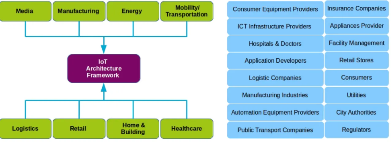
Figure 2.1 Internet of Things Stakeholders.
ETSI has defined Machine-to-Machine communication architecture and a global partnership calledoneM2M[4] has been established to develop standards for Machine-to-Machine communication.
The term Cyber Physical Systems is defined by the National Institute of Standards and Technology (U.S. Department of Commerce)[5] as follows:
Cyber-Physical Systems or "smart systems are co-engineered interacting networks of physical and computational components. These systems will provide the foun-dation of our critical infrastructure, form the basis of emerging and future smart services, and improve our quality of life in many areas[5].
Internet of Things covered a vast range of industries, applications, and use cases. Figure 2.1 lists potential stakeholders in the Internet of Things domain. Few of the areas listed in Figure 2.1 already have a considerable deployment of IoT e.g. home automation, manufacturing, logistics, etc.
2.2
Internet of Things Technologies
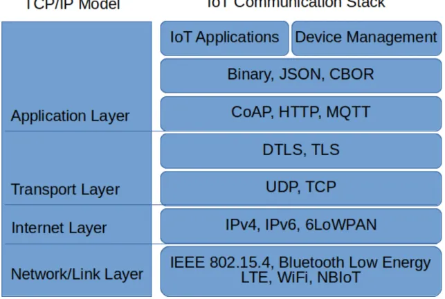
In the Internet of Things, different technologies are in use to facilitate communi-cation and data exchange between the endpoints. Figure 2.2 describes an example of an IoT communication stack compared with TCP/IP model. The Internet uses TCP/IP model or OSI model to divide the protocols into different layers, depending upon their roles. In the Internet of Things, we can also use the similar model to
Figure 2.2 Comparison of Internet of Things communication stack with TCP/IP model
classify the IoT protocols. In addition to that, the Internet of Things includes other application layer technologies that facilitate the communication in an IoT network. Therefore, instead of fitting all of the IoT protocols and technologies in TCP/IP model or OSI model, the thesis introduces a new model described in Table 2.1 to provide a better classification of the IoT technologies[6]. Using this model we can organize the IoT protocols and other related technologies in a single model based on their roles.
Table 2.1 Layer Model of IoT Technologies
8 Semantic 7 Device Management 6 Discovery 5 Data Protocols 4 Transport Layer 2 Internet Layer 1 Network/Link Layer
The following section outlines a brief explanation of the roles and examples of as-sociated technologies at each layer. Understanding of these layer’s functions will provide a base to solve the semantic interoperability problem.
2.2.1
Network/Link Layer
This layer works with hardware and provides connectivity between endpoints. It includes the technologies that provide physical connectivity and link-local addressing features. Few prominent IoT technologies at this layer are,
IEEE802.15.4: IEEE802.15.4[7] is a protocol for low-rate wireless personal area networks. This protocol is used with 6LoWPAN[8] in conjunction with IPv6[9].
Zigbee: Zigbee protocol[10] uses IEEE802.15.4 standard and operates on 2.4 GHz frequency with 250 Kbps output. Zigbee can have a maximum range of up to 200 meters.
Bluetooth Low Energy: Bluetooth Low Energy(BLE)[11] also known as Blue-tooth Smart is a technology for personal area networks. It uses 2.4 GHz ISM band and has a 100 meters range. Bluetooth Low Energy is defined by Bluetooth Special Interest Group.
NB-IoT: Narrowband IoT (NB-IoT)[12] is a Low Power Wide Area Network (LP-WAN) radio technology standardized by 3GPP[13] for IoT. NB-IoT focuses on indoor coverage, long battery life, and low cost for a large number of devices.
2.2.2
Internet Layer
Internet layer protocols provide addressing/identification to IoT devices. Following are examples of this layer technologies.
Internet Protocol: Internet Protocol (IP) is the widely used protocol for address-ing devices at the network layer in the computer networks. Internet Protocol has two versions Internet Protocol version 4 (IPv4)[14] and Internet Protocol version 6 (IPv6)[9]. IPv4 provides 32bit addresses while the IPv6 provides 128-bit addresses.
6LoWPAN: 6LoWPAN[8] is a networking technology to carry the IPv6 packets over the low rate wireless networks such as IEEE 802.15.4. It stands for IPv6 over Low power Wireless Personal Area Networks. 6LoWPAN provide 250 Kbps data rate over a 2.4 GHz frequency.
In addition to IPv6, the Internet of Things include 6LoWPAN at Internet layer. 6LoWPAN is IPv6 adaptation layer for IoT.
2.2.3
Transport Layer
Transport layer includes protocols to establish end-to-end communication channel. Examples of transport layer protocols include:
TCP: Transmission Control Protocol (TCP)[15] provides logical end-to-end con-nection on process level. It works with IP protocol to establish a reliable commu-nication channel. TCP provides ordered delivery of packets, error checking, and retransmissions features.
UDP: User Datagram Protocol (UDP)[16] provides ports numbers for identifying the different application or multiple sessions of an application. UDP is used in combination with IP to create communication sockets.
QUIC: Quick UDP Internet Connection (QUIC) support multiplexed connection between two endpoints over UDP. QUIC is designed to provide security equivalent to TLS/SSL, lower latency, and congestion avoidance through bandwidth estimation. There are some IETF drafts that describe the specifications of QUIC[17] protocol at the time of this writing.
TLS: Transport Layer Security(TLS)[18] provides three functions, encryption, au-thentication and integrity. TLS has two layers, TLS Record Protocol and TLS Handshake Protocol. TLS Record Protocol provides data connection security. TLS Handshake Protocol provides authentication and negotiation of encryption algorithm between client and server.
DTLS: Datagram Transport Layer Security (DTLS)[19] ensure the security for UDP segments. It prevents the UDP segment against eavesdropping, tampering or message forgery. DTLS is based on TLS.
TLS and DTLS protocols are used to establish secure communication channel over UDP and TCP respectively. The TCP/IP model include these protocols at appli-cation layer. In this model we include these protocols at transport layer to simplify things at upper layers.
2.2.4
Data Protocols
Data protocols layer includes protocols used for data exchange between devices. Below is a brief description of well-known data protocols for IoT.
HTTP/HTTPS: Hyper Text Transfer Protocol[20] is used to transfer web pages. IoT devices can also use HTTP as data transfer protocol. HTTP is a stateless application protocol to encode and transport information between a client and a web server. HTTP uses request-response semantics and a particular type of URI called Uniform Resource Locator (URL) which identify the resources. HTTPS[21] stands for HTTP over TLS. It is a secure version of HTTP protocol to provide secure communication between a client and a server.
MQTT: Message Queuing Telemetry Transport (MQTT)[22] is a messaging pro-tocol based on an event-driven architecture (Publish/Subscribe) that enables MQTT to send push messages to the receiver. MQTT Broker handles the communication between MQTT nodes. A node publishes a message to the broker. Each message contains a topic information. The topic is like routing information. Any node that subscribes to the topic receives all messages related to the topic.
CoAP: Constrained Application Protocol (CoAP)[23] is a specialized web trans-fer protocol for constrained devices and constrained networks. CoAP uses Request-Response interaction model. CoAP defines status codes to inform the client about the operation results. It uses UDP as the primary transport protocol. CoAP sup-ports built-in discovery, asynchronous message transfer, block transfer, multicast and observe. CoAP also provides reliability over UDP using confirmable messages. CoAP architecture is composed of two parts, messaging model, and request-response model.
CoAP Messaging Model is based on the exchange of messages over UDP. The sim-ple and concise header of CoAP protocol, minimize the header size overhead for small packets in IoT domain. CoAP provides reliability by marking messages as confirmable and receives acknowledgments from the recipient.
CoAP Request-Response Model carries request-response semantics in CoAP mes-sages as method code or response code. CoAP options carry the optional informa-tion like URI, path, content format, etc. The CoAP header contains a token to relate a response to the corresponding request.
Similar to HTTP, CoAP is also a REST based protocol. CoAP is already being used in many IoT applications and devices.
In addition to the above-mentioned protocols, few other protocols and frameworks related to data exchange are Advanced Message Queuing Protocol, WebSocket, Ex-tensible Messaging and Presence Protocol(XMPP), Simple Object Access Protocol (SOAP) etc.
2.2.5
Discovery
In the Internet of Things, the discovery of devices and their resources is critical. Fol-lowing are examples of well-known technologies and specification for device discovery or resource discovery.
DNS: Domain Name System(DNS)[24, 25] is a way of mapping the domain name of a machine to its IP address. The mapping information is called DNS record. DNS records are stored on a server call DNS server. To use DNS service, a client sends the domain name e.g “example.com”, in a request message to a DNS server.
The DNS server replies back with an IP address of the corresponding machine if a matching record is found.
Multicast CoAP: A CoAP client makes a multicast request to find CoAP server running on a multicast address and default CoAP port. The multicast address for CoAP is named as All CoAP Nodes address. The multicast address for IPv4 is
224.0.1.187 and for IPv6 is FF0X::FD. A client can discover resources on a CoAP server by sending a GET request to /.well-known/core.
Core Resource Directory: Core Resource Directory[26] is a specification of a resource directory server to register and discover resources in an IoT network. A resource directory hosts the description of resources hosted on other web servers. The Core Resource Directory specifies the web interfaces for the resource directory server. The web interfaces are used by the web server to register, update, delete resource descriptions in the resource directory. The clients can retrieve resource descriptions using a GET request.
UPnP: Universal Plug and Play (UPnP) is a set of protocols to discover and a establish connection to other endpoints.
Few more examples of discovery protocols are mDNS, Physical Web DNS-SD, SSDP, XMPP Service Discovery, etc.
2.2.6
Device Management
Device management is related to identity and access management of IoT devices. Device management is divided into the following functions, provisioning, authenti-cation, configuration, control, monitoring, diagnostics, maintenance, and software updates. OMA LWM2M, OMA DM, and TR069 are the examples of well-known de-vice management protocols. Among the above-mentioned protocols, OMA LWM2M is specifically designed for constrained devices in an IoT network.
OMA LightweightM2M: OMA LightweightM2M (OMA LWM2M)[27] is a de-vice management protocol from Open Mobile Alliance (OMA). OMA LWM2M
pur-pose is to facilitate the fast deployment of client-server M2M services. On protocol stack, OMA LWM2M uses Efficient Payload(plain text payload for individual re-sources), CoAP Protocol, DTLS Security, and UDP/SMS Bearer. For client-server communication, LWM2M define following four interfaces between OMA LWM2M Server and OMA LWM2M Client.
• A bootstrapping interface that provides information for the OMA LWM2M client to register with the OMA LWM2M server. OMA LWM2M enabler supports three bootstrapping methods, pre-provisioned bootstrapping, boot-strapping via smartcard and client/server initiated bootboot-strapping.
• A registration interface registers a client and its objects with LWM2M Server. Registration interface supports registration, update and de-register functions.
• A device management and service enablement interface provides access to LWM2M client objects and resources for LWM2M server. This Interface sup-port “write”, “read”, “create”, “delete”, “execute”, “write attributes” and “dis-cover” operations. An object template defines the operations supported by a resource.
• An information reporting interface is used by LWM2M server to observes any changes in LWM2M client resources. Information reporting interface support “observe”, “notify” and “cancel observe” operations.
2.2.7
Semantic
Semantics is the mutual understanding on the meaning of shared data. In the following section, we will discuss the technologies that help to provide data semantics in IoT.
JSON-LD: JSON-LD[28] is an acronym of JavaScript Object Notation- Linked Data. It is composed of two parts, JSON and Linked Data. Linked data provides interlinking between the data on Web, so that it is understandable by computers. On the other hand, JSON is a data serialization format. Together JSON and Linked Data create an enhanced version of JSON data serialization called LD. JSON-LD uses context to provide the mapping between JSON and RDF model. This helps to make relations between the properties of an object described in a JSON document and the related concepts in the ontology of an object.
RDF, RDF Schema, and OWL: Resource Description Framework (RDF)[29] is the standard data representation model on the semantic web. RDF represents data as RDF statements. RDF statements are written as a triple.
subject – predicate – object
The subject in a triple denotes the resource usually specified by a URI. Object denotes another resource or entity. The predicate describes the relationship between the subject and object e.g. apple colour is red. In that example “apple” is subject, “red” is an object, and “colour” is the predicate that associates the red colour with an apple.
RDF Schema[30] is the vocabulary for RDF data. It is an extension to RDF data model and provides semantics to RDF data. RDF Schema expresses the relation between resources by grouping related RDF resources. RDF Schema defines the concept of classes, property, domain, range. Resource groups in RDF Schema are called classes. Property is equivalent of a predicate; it defines a relation between subject and object. Domain and range are the additional constraints to provide semantic meaning to data.
Web Ontology Language (OWL)[31] is semantic web language designed to represent complex knowledge and relationships about things. Documents of OWL are referred as Ontologies. Ontologies are described in section 3.3.3. OWL statements are writ-ten using RDF statements. The commonly used representation language for RDF is XML. RDF also support JSON[32] as an alternative to the XML.
Thing Description: Thing Description[33] is a model defined by W3C to describe metadata and interaction properties of an IoT device. Thing Description uses RDF as underlying data model and JSON-LD as a serialization format. Thing Description has four parts:
• Semantic Metadata: It provides thing generic information and context e.g. vocabulary to define the semantics of things and encoding, supported protocols
• Security: It provides information about the prerequisites to access things and resources e.g. authentication, authorization.
• Communication: It provides information about supported protocols, address location e.g. HTTP, CoAP, etc. and bindings to an interaction resource.
• Interaction Resource: Things interaction resource contains information about thing interactions and functions. It is further divided into:
– Property interaction of a Thing Description provides information of hosted resource data. The data can be static or dynamic. The “writable” attribute defines if data is read-only or writable. Another important information is media type and serialization format of the available data.
– Action field defines the processes that a device can perform, or it is as-sociated. Actions are changes or processes that require time to complete, e.g. fan control, brewing Coffee.
– Eventinteraction defines the ability of a device to notify peer nodes upon certain conditions.
Each section of interaction resource contains meta-data about things supported data format/value types, units, links, etc.
While W3C Web of Things Interest Group defines a vocabulary for Thing Descrip-tion, it can also make use of external vocabulary through context field defined in Thing Description.
3.
INTEROPERABILITY IN THE INTERNET
OF THINGS
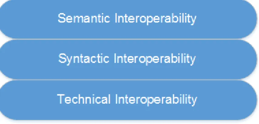
Interoperability is the ability of information systems to exchange, interpret, and understand the unambiguously shared meaning of the information. Interoperability enables a device to work with other devices seamlessly. In the IoT domain, we can divide interoperability into three layers: Technical Interoperability, Syntactic Interoperability, and Semantic Interoperability. Figure 3.1 list interoperability layers in the order of their dependability. Each layer of this interoperability model is the prerequisite for upper layers[34].
Before we discuss the three layers of interoperability, an understanding of the differ-ence between data data model and information model is a prerequisite. The infor-mation model is the conceptual modeling of managed objects independent of any im-plementation or underlying protocol. It describes the relationships between objects. On the other hand, a data model describes the implementation and protocol-specific details of these objects. Further details of the difference between the information model and data model can be referenced in [35]. Following section provide a brief introduction to the above-mentioned interoperability layers.
3.1
Technical Interoperability
The basic requirement for interoperability is Technical Interoperability. Technical Interoperability is defined as the ability of a device to communicate with other devices and is associated with hardware/software components e.g. two devices can communicate using Bluetooth LE or 6LoWPAN. The Network/Link Layer of IoT Technologies model 2.1 provide the technical interoperability.
Figure 3.1 Layered structure of interoperability.
3.2
Syntactic Interoperability
Once communication is established, the next step is syntactic interoperability. Syn-tactic interoperability deals with the data models, communication protocols, data formats, data encoding, and serialization techniques. To achieve syntactic interoper-ability, devices must agree to use same standards on both ends. Providing syntactic interoperability in IoT systems and achieving a consensus is a challenging work. Many organizations and consortia have been developing syntactic interoperability standards for use in IoT domain. The technologies from the Data Protocols layer of IoT Technologies model 2.1 provide the syntactic interoperability.
The technologies from discovery and device management layers do not directly pro-vide the interoperability, but, they facilitate the communication through discovering resources and managing devices in an IoT Network.
3.3
Semantic Interoperability
Semantic Interoperability is related to the meaning of content and is the ability of entities to understand unambiguous, shared meaning of data. In Information Systems like IoT, devices must be able to exchange information in a way that precise meaning of data is understood. Following approaches are currently in use to provide semantic interoperability in an IoT network.
3.3.1
Proxy Gateway
Proxy gateway acts as an intermediate node in communication. Like any other proxy server, it sends requests and delivers responses on behalf of some other nodes. The proxy gateway can communicate with nodes in their native data model and encoding scheme. This enables a transparent communication between nodes. One example of such proxy gateways is “data model translator”. Data model translator is an entity in the network that performs translation between two data models. This approach is simple and provides the ability to communicate but implementing a data model translator that has knowledge of mapping between data models and encoding scheme for all the devices in a heterogeneous network is a complex task and does not scale well. This approach also makes the proxy gateway as a single point of failure in the network. Despite its shortcomings proxy gateway can be useful in a small network[36]. A proxy gateway can provide technical interoperability service (e.g., a proxy gateway with two radio interfaces IEEE 802.15.4 and LTE, can receive data from sensors using IEEE 802.15.4 and then send that data to a server using LTE radio).
3.3.2
Unified Data Models and Frameworks
One approach to solving semantic interoperability problem is through unified data model for all devices. Unified data models provide a universal data model to use in IoT devices. There are some initiatives to develop such models and frameworks e.g. IPSO Smart Objects. LWM2M objects, Cluster Library (Zigbee Alliance) and ETRI Data Model (based on Yang Model). These models provide syntactic and semantic information, but that is not enough to provide a general solution for large-scale IoT implementation as the communication between such frameworks still require an external device e.g. proxy gateway.
3.3.3
Ontologies
Ontology is defined as the formal specification of a concept. It is a working model of the types, properties, interactions, and the relationship of entities in a system. Ontologies can provide semantic interoperability in IoT by providing the contex-t/reference to a wide range of vocabulary. Ontology has four main components:
class, individuals, attributes and relations[31, 37]. Classes can have sub-classes and attributes. Relations in an ontology connect the instances of a class and a subclass. Such instances are called individuals. Ontologies are not limited to physical objects, they are extended to virtual objects and models. Examples of this approach are SSN Ontology[38], IoT-O Ontology[39] and Thing Description 2.2.7.
4.
PROPOSED SEMANTIC
INTEROPERABILITY SOLUTION FOR IOT
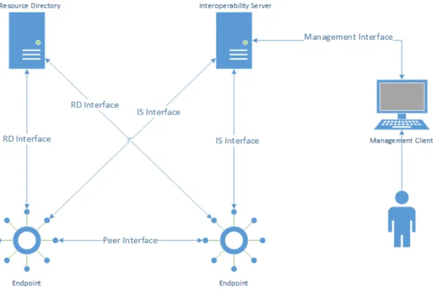
Use of standardized protocols and other IoT technologies helps to solve the syntactic interoperability problem. The semantic interoperability issues at application layer still require attention. As described in section 3.3, the semantic interoperability is related to the agreement on the meaning of data and solving the semantic inter-operability problem is a two-step process. First, we need to devise a method to solve the problem and then select appropriate standards and protocols that support our method. Many working groups, consortia, organizations, or academia have de-veloped protocols, data model, vocabulary, information models, and Ontologies to solve the various parts of the semantic interoperability problem in IoT. In chapter 2, we learned about many IoT protocols, standards and different approaches to solve semantic interoperability problem. Now, we step forward to design a solution that complies with our research goal for this thesis. Figure 4.1 represents the topology of our designed solution and has following entities.
• Endpoint
• Resource Directory
• Interoperability Server
• Peer Interface
• Resource Directory Interface
• Interoperability Server Interface
• Management Interface
Among the above-mentioned components, Interoperability Server and Management Client, IS Interface, Management Interface are implemented by this thesis. The
Figure 4.1 Topology of the Prototype using Thing Description for Semantic Interoper-ability
Resource Directory is specified in IETF draft[26] of Core Resource Directory. The Endpoints are standard CoAP client and server devices. In addition to standard options, the thesis introduces a new mandatory option for registering resources in Resource Directory. Details of above-mentioned components, interfaces, and their role in the prototype are discussed in the following section.
4.1
Endpoint
An endpoint is an IoT device. An endpoint is usually the device running an IoT application or providing some data to other IoT applications, e.g., a temperature sensor, light bulb, coffee maker, controller, etc. An endpoint can be a physical or emulated device or a software instance representing device functions. This thesis implements the endpoints as virtual devices. The endpoints use the CoAP protocol for data exchange and support CoAP GET, POST, PUT, and DELETE methods for different operations.
4.2
Resource Directory
Resource Directory (RD) is specified in an IETF draft[26] (at the time of this writ-ing). In an IoT network, a Resource Directory provides the resource discovery ser-vice. It hosts the description of the resources that are hosted on other constrained servers. This description of each resource is in the form of a web link. Thus a Resource Directory can also be referred as a repository of the web links of the re-sources hosted on the IoT endpoints, and a client can perform a lookup on Resource Directory to discover these resources. This way the Resource Directory solves the resource discovery problem when the IoT endpoints are in sleep mode or do not support resource discovery.
An IoT endpoint advertises its resources to the Resource Directory by sending the registration message. A registration message is in the form of a REST POST request. Following is a sample POST request for resource registration.
POST coap://rd.example.com/rd?ep=node1&ct=41&sem=td1
The parameters ep is endpoint name and ct is the content type. These parameters are defined in Core Resource Directory draft at IETF [26]. Details of parameters
ep, ct are described in Section 4.4.2. The parameter sem is introduced in this thesis as a semantic identifier of an IoT endpoint and it uniquely identifies the endpoint (the constrained server that hosts the resource) in the Interoperability Server. The endpoint obtains its semantic identifier from the Interoperability Server, before reg-istering with Resource Directory. The method of obtaining semantic identifier is described in section 4.3.
An IoT endpoint can also update its registration on the Resource Directory. An IoT endpoint that does not support the registration mechanism, can make their resources available at “/.well-known/core” address. The Resource Directory can scan these resources by sending a GET request at “/.well-known/core” address on each server to retrieve and register these resource. The Resource Directory specifies REST based "RD Interface" for communication. The details of the RD Interface are described in section 4.4.2.
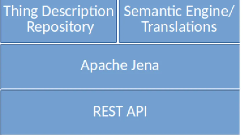
Figure 4.2 Interoperability server model
4.3
Interoperability Server
Interoperability Server (IS) is the main component of our solution. The main func-tions of Interoperability Server are to store Thing Descripfunc-tions of endpoints and provide a translation for resources hosted on an endpoint. For communication, Interoperability Server specifies two interfaces, a northbound interface called "Man-agement Interface", for communication with a Man"Man-agement Client and a southbound Interface called "IS Interface" for communication with the endpoints. Both of these interfaces provide REST APIs for sending and receiving requests. Section 4.4.3 de-scribes the supported operations on IS interfaces. The Management Interface of Interoperability Server supports HTTP protocol. The IS Interface supports CoAP protocol for data transfer. Section 2.2.4 provided a brief introduction of CoAP and HTTP. Before we discuss in detail the functionality of Interoperability Server and its interfaces, let’s take a look at the anatomy of Interoperability Server. The Inter-operability Server is composed of the entities mentioned in Figure 4.2. In upcoming section, we will briefly discuss each component of the Interoperability Server.
4.3.1
Apache Jena
Apache Jena[40] is the open source framework to build semantic web and linked data applications. It provides a high-performance database called TDB to store RDF triples. Apache Jena provides RDF API to query TDB and also supports the SPARQL query language. Apache Jena TDB has two types of RDF graphs called
contain one default graph and can have one or more than one named graph. The thesis uses the Apache Jena TDB to store Thing Descriptions of endpoints inside Interoperability Server.
4.3.2
Thing Description Repository
Thing Description Repository is a storage for the Thing Descriptions of endpoints. The Thing Description Repository is based on Apache Jena TDB. Thing Descrip-tion Repository uses default graph to store the indexes and meta-data of the Named Graphs. When Interoperability Server receives a request to register Thing Descrip-tion of an endpoint, it stores Thing DescripDescrip-tion in Thing DescripDescrip-tion Repository as follows:
• Thing Description data is parsed as RDF graph. This RDF graph is stored as named graph in the Thing Description Repository.
• An entry is created in default graph to store index and meta-data of newly created name graph.
• Interoperability Server allocates a URI called Resource URI to the stored Thing Description.
• Thing Description text is stored in default graph using Resource URI as the key.
The Resource URI can be used to retrieve, update or delete Thing Description from Thing Description Repository. The Resource URI is constructed using the Base URI of the endpoint represented by the Thing Description, Thing Description storage path in Interoperability Server and a unique Semantic ID generated by Interoperability Server. An example of Resource URI is:
http://www.example.com/td/ef124d6d
The Semantic ID is same for a set of similar endpoints. To understand why a set of similar endpoints have a same Semantic ID, consider the following scenario:
Every endpoint connected to an IoT network has a unique URI that is usually a URL address. There can be multiple endpoints with exactly the same functionality e.g. multiple motion sensors in an office. So, their Thing Descriptions will be exactly the same, except URI of the endpoint. Also, an endpoint can have more than one URIs which are either completely different from each other or the same URI with different schemes e.g. CoAP, and HTTP.
The mentioned scenario would have resulted in a different Resource URI inside In-teroperability Server for endpoints with exactly same functionality. Such a situation may not be a problem for smaller IoT networks, but with larger networks, it will increase the complexity of managing endpoints Thing Descriptions inside Interop-erability Server. It will also require redundant efforts to provide translations of resources hosted on these endpoints.
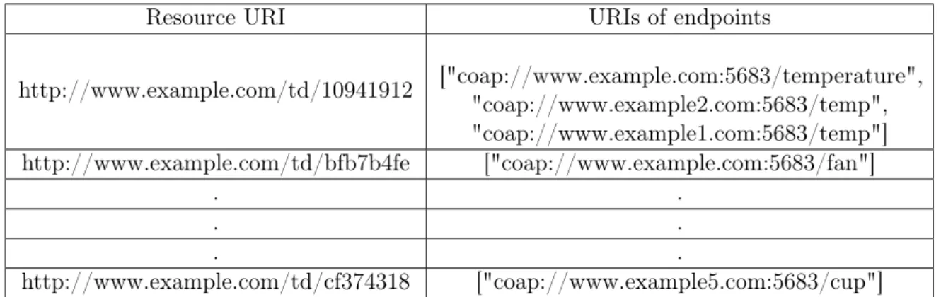
Interoperability Server provides a solution to this problem by introducing a mapping service between URI of an endpoint and Resource URI. This mapping service is named as UriMap. UriMap is a table of mappings between Resource URI and URIs of similar endpoints, as shown in Table 4.1. All the endpoints that have the exact same Thing Description except their URI will have same Resource URI inside Interoperability Server. Using this approach, we have successfully reduced the amount of work for the administrating Thing Descriptions and translations when using the manual approach to create translations (as described in section4.3.3).
Resource URI URIs of endpoints
http://www.example.com/td/10941912 ["coap://www.example.com:5683/temperature", "coap://www.example2.com:5683/temp", "coap://www.example1.com:5683/temp"] http://www.example.com/td/bfb7b4fe ["coap://www.example.com:5683/fan"] . . . . . . http://www.example.com/td/cf374318 ["coap://www.example5.com:5683/cup"] Table 4.1 Resource URI vs Associated URI Mapping
The first row in Table 4.1 shows a Resource URI associated to a list of URIs of different endpoints. As described in Figure 4.2, the Interoperability Server has two main components Thing Description Repository and Semantic Engine. In the previous section, we have discussed the Thing Description Repository in detail, Let’s
have a look at the Semantic Engine part of Interoperability Server.
4.3.3
Semantic Engine
Semantic Engine is an important component of Interoperability Server. It provides translation service for the resources hosted on IoT endpoints. By using these trans-lations, an endpoint will have access to the context and meta-data of a resource it wants to retrieve from the peer endpoint. The Interoperability Server design incor-porates two models to create translations. The first method is manual approach by an Interoperability Server administrator, the second method is to automatically cre-ate the requested translations using Thing Descriptions and Ontologies of endpoints with technologies like semantic reasoning using Ontologies, and machine learning. As the complexity of the second method is beyond the scope of this thesis work, we will use the manual approach to create translations for the proof of concept. Following is the explanation of how these approaches work.
Manual Approach
In manual approach, an administrator of Interoperability Server creates translations for resources hosted on endpoints in an IoT network. The main purpose of a trans-lation is to include the meta-data related to the resource payload and information about vocabulary to provide the context for meta-data. The translation should be created and stored in Interoperability Server before an endpoint requests for it. For the missing translations, the Interoperability Server generates a translation requests when an endpoint query the Interoperability Server for a translation and that spe-cific translation is not found in Interoperability Server. Later, an administrator of the Interoperability Server queries Interoperability Server for translation requests and creates the requested translations. To create a translation, the administrator searches for the Thing Description of requesting endpoint and target endpoint. If the Thing Description of the requesting and target endpoint is found in Interoperability Server, the administrator follows the following steps to create a translation:
Compare the vocabulary for both Thing Descriptions. If requesting endpoint uses a different vocabulary than target endpoint, use the vocabulary of re-questing endpoint in translation.
Collect all the information about the resource from target endpoint Thing De-scription.
Create the translation object with context and resource properties.
Context includes the reference to the vocabulary used in translation.
Resource properties include information about request and response operation
Request part includes information on how to get/update the specified resource, what kind of media type is supported etc.)
Response part includes meta-data about the requested resource.
The Interoperability Server stores the translations the same way as Thing Descrip-tion. The Path of a translation Resource URI /translate distinguishes between a Thing Description and a translation. The translation name is derived from the Se-mantic ID of the requesting and target endpoint Thing Descriptions, as mentioned below:
<requesting: Semantic ID>_<target: Semantic ID>_<resource type>
e.g. if the Semantic ID of requesting endpoint is 965f6543, and Semantic ID of target endpoint is 56d98v74, and resource type is temperature, then the ID of the translation will be 965f6543_56d98v74_temperature. The thesis does not restrict the way a translation can be created manually, although, the translation needs to comply with the Thing Descriptions of requesting and target endpoints. The data encoding can be in any format as long as the endpoints in the network use the same. The thesis uses JSON format for encoding/decoding purpose.
Automatic creation of Translations
The overall design of this semantic interoperability solution is that Interoperability Server should automatically generate the translation upon request. For that purpose the Interoperability Server requires intelligence. As machine learning and artificial intelligence are trying to make ways into the IoT domain, there is a possibility to use these technologies to create required functionality. Machine learning requires
sample data for algorithm training before it can produce desired results. The sample data in our case are Thing Descriptions of endpoints. However, Thing Descriptions only provide information about the endpoints, and we require more data that can somehow provide inferencing information about the Thing Descriptions data. For this purpose, another standard technology Ontologies from W3C can provide the necessary functionality. Section 3.3.3 briefly describes the Ontologies . Ontologies have their application in semantic web to provide inferencing on linked data. We believe, the combination of Thing description along with Ontologies can provide similar inferencing capabilities to generate translation about a target resource. As the implementation of this approach requires expertise in machine learning and artificial intelligence, we leave this work as future enhancements to the solution.
As discussed earlier, the Interoperability Server is using the manual approach to create translations, it requires an administrative interface to manage Thing De-scriptions and translations. For this purpose, we have developed a management client for our semantic interoperability solution.
4.3.4
Management Client
The management client as the name suggests provides a web interface for an ad-ministrator of the Interoperability Server to store and manage Thing Descriptions and translation. The management client resides as a separate entity to ensure com-patibility and simplicity of the project for future development. The management client is based on REST architecture and communicates with the Interoperability Server over REST based management interface. It provides the capabilities to view, create, modify and delete Thing Descriptions and translations. Further details of these capabilities are listed under section 4.4.4
4.4
Interfaces
The semantic interoperability solutions have specified following interfaces to facil-itate communication between different entities. The following section briefly de-scribes each interface in detail.
4.4.1
Peer Interface
Peer Interface is used between two endpoints. This interface is based on REST model and can support CoAP or HTTP. Our recommendations for this interface is to use CoAP as data transfer protocol. Using CoAP to interact with peer endpoints and retrieve data is lightweight and will comply with the resource-constrained nature of IoT endpoints. The peer interface does not have any strict specifications. The peer interface supports the CoAP standard request-response architecture to send and receive data i.e CoAP Requests and CoAP Response messages, options, URI schemes, content formats.
4.4.2
Resource Directory Interface
RD Interface provides the communication capabilities of the Resource Directory. It provides the Resource Directory functions accessible to Endpoints. Resource Directory functions are standardized in [26]. Following are the available functions that endpoint can perform on RD interface.
Register a Resource
Endpoints can register their resources to the Resource Directory using the CoAP POST command. The registration operation requires two parameters “ep, sem” followed by few optional parameters. The specification of this operation is,
Method: POST
URI Template: /rd?<parameters>
Parameters: ep=<mandatory: endpoint name>&sem=<mandatory:endpoint Semantic ID>&<optional:d,lt,con>
Content-Type: application/<JSON or link-format>
Payload: content of JSON or link-format file
Success: 2.01 Created (returns an ID of the resource in Resource Directory)
Failure: 5.03 Service Unavailable (some internal error in RD)
The optional parameters are,
“d” : domain where endpoint belongs “lt” : life time of the registration in seconds
“con” : this parameter sets the scheme address and port e.g “scheme://host:port/path”.
Update a Resource
Endpoints can update their resource by sending a CoAP PUT request to the Re-source Directory. The specification of this operation is,
Method: PUT
URI Template: /rd/<resource ID>
Parameters: <optional:lt, con>
Content-Type: application/<JSON or link-format>
Payload: content of JSON or link-format file
Success: 2.04 Changed
Failure: 4.00 Bad Request (some error in the request parameters or payload)
Failure: 4.04 Not Found (if the requested resource does not exist in RD)
Failure: 5.03 Service Unavailable (some internal error in RD)
The optional parameters are defined as, “lt” : life time of the registration in seconds
“con” : this parameter sets the scheme address and port e.g “scheme://host:port/path”.
“/rd-group/” path is used to create a group of endpoints. All group operations are supported on RD interface using this path. “rd-group” require one mandatory and two optional parameters,
“d” : domain where group belongs
“con”: this parameter sets the scheme address and port where the server is available
Lookup a Resource
Endpoints can perform a lookup for a resource or peer endpoint containing some specific resource type. Endpoints send a CoAP GET request to the resource direc-tory and specify a lookup type. An endpoint can specify optional parameters to filter lookup results. Following is the lookup operation specification,
Method: GET
URI Template: /rd-lookup/<lookup-type: ep, res, d, gp>
Parameters: <optional:ep, d, rt, et>
Success: 2.05 OK ()payload containing information about resource including semantic ID of the target endpoint)
Failure: 4.00 Bad Request (some error in the request parameters or path)
Failure: 4.04 Not Found (if the requested resource does not exist in RD)
Failure: 5.03 Service Unavailable (some internal error in RD)
The lookup type is defined as,
“ep”: endpoint name can also be used as parameter “res”: type of resource
“d” : domain where resource or endpoint belongs “gp”: group where resource belongs
Optional parameters include “ep", "d” as defined above and, “rt”: type of resource e.g. light
“et”: endpoint type e.g. sensor
Many other operations are defined in [26] (e.g. delete a resource, group registra-tion, and group update, etc.) and are available on RD interface. For our semantic
interoperability solution, the mandatory requirements on RD Interface are resource registration, resource update and resource lookup. The RD Interface also supports the resource removal operation.
4.4.3
Interoperability Server Interface
IS Interface also follows the REST model and provides the communication capa-bilities between interoperability server and endpoints. This thesis formalizes the IS Interface to ensure compatibility across the whole IoT domain. IS Interface pro-vides the registration and update operation of Thing Description in Interoperability Server. IS Interface also provides lookup functionality for translations. IS Interface uses CoAP protocol for data transfer between endpoints and Interoperability Server. Endpoints can perform the following operations over the IS Interface,
Register a Thing Description
An Endpoint can register its Thing Description by sending Thing Description con-tent as the payload of CoAP POST request on “/td/” path. Following is the specification of this operation.
Method: POST
URI Template: /td
Content-Type: application/ld+jso
Payload: Content of a JSON-LD file representing the Thing Description of an endpoint.
Success: 2.01 Created a new entry in Interoperability Server.
Failure: 4.00 Bad Request (some error in the payload)
Failure: 5.00 Internal Server Error (if there is some error in processing payload or registering Thing Description)
Update a Thing Description
Endpoints can update their Thing Description by sending the updated content in the payload of PUT operation on “/td/<Semantic ID>” address. Following is the specification for this operation.
Method: PUT
URI Template: /td/<Semantic ID>
Content-Type: application/ld+json
Payload: content of a Updated Thing Description file
Success: 2.04 Changed
Failure: 4.00 Bad Request (some error in the request payload or the existing TD is not found in the database)
Failure: 5.00 Internal Server Error (some error in processing the payload or updating the TD)
Lookup Translations
Endpoints can lookup a translation of a target resource by sending a GET request on “/translate-lookup” address and specify the source endpoint Semantic ID, target endpoint Semantic ID and resource type. The following specification explains the GET request in detail.
Method: GET
URI Template: /translate-lookup?<parameters>
Parameters: source=<source endpoint Semantic ID>&target=<target endpoint Semantic ID>&rt=<resource type>
Success: 2.05 Content (the translation data is sent in the payload)
Failure: 5.00 Internal Server Error (if there is some error processing the param-eters or getting the translation from the database)
4.4.4
Management Interface
The Management Client uses the Management Interface to communicate with the Interoperability Server. The Management Interface is based on the REST model. The management client uses the HTTP protocol to communicate with the Interop-erability Server. All the operations performed on the IS Interface are also possible on the Management Interface. The return code of update and lookup functions will be different to comply with HTTP standards. Upon successful Thing Description update request, the return code on Management Interface is 200 OK. Similarly, upon successful lookup request for translation, the return code on Management Interface is 200 OK.
In addition to the operations specified by IS Interface, the following functions are available on the Management Interface:
GET a Thing Description
The Management Client can retrieve a specific Thing Description from the Interop-erability Server database by sending an HTTP GET request and specify the Thing Description path as request URI. The complete specification of the operation is given as follows.
Method: GET
URI Template: /td/<Semantic ID>
Success: 200 OK (content of Thing Description as JSON-LD document)
Failure: 404 Not Found (if the TD is not present)
Failure: 500 Internal Server Error (if there is some error deleting a TD form the database)
Delete a Thing Description
The Management Client can delete a specific Thing Description by sending a HTTP DELETE request to the Interoperability Server, specifying the Thing Description resource URI. The specification of this operation is given below,
Method: DELETE
URI Template: /td/<Semantic ID>
Success: 200 OK
Failure: 404 Not Found (if the TD is not present)
Failure: 500 Internal Server Error (if there is some error deleting Thing Descrip-tion form the database)
List All Thing Descriptions
The Management Client can request the list of all registered Thing Descriptions from the Interoperability Server. The Management Client will send an HTTP GET request to the Interoperability Server on the “/td” path, and the Interoperability Server will send all the registered TDs in return. Following is the specification of this operation,
Method: GET
URI Template: /td?<parameters>
Parameters: <query, text, rdf> to filter results
Success: 200 OK (Content of all Thing Descriptions stored in Interoperability Server database)
Failure: 400 Bad Request (some error in the request parameters)
Failure: 500 Internal Server Error (if there is some error processing the param-eters or getting a translation from the database)
The request parameters are optional and are defined as, “query”: a sparql query in form <?s ?p ?o>
“text” : text based search for TDs e.g light “rdf” : rdf triple to search for TDs
Register a Translation
The Management Client registers a translation of a specific resource. The Man-agement Client sends an HTTP POST request to Interoperability Server specifying all necessary parameters and includes the translation data in the payload of the message. The detailed specification of the operation is given as,
Method: POST
URI Template: /translate?<parameters>
Parameters: source=<source endpoint Semantic ID>&target=<target endpoint Semantic ID>&rt=<resource type>
Content-Type: application/<JSON, XML or other supported types>
Payload: the content of a translation file
Success: 201 Created
Failure: 400 Bad Request (if there is some error in the request parameters or the payload)
Failure: 500 Internal Server Error (if there is some error storing the translation in the database)
Update a Translation
The Management Client can update a translation by sending an HTTP PUT request to the Interoperability Server. The update request does not require any parame-ters and only includes the translation information in the payload. Following is the specification of this operation,
Method: PUT
URI Template: /translate/<translation ID>
Content-Type: application/<JSON, XML or other supported types>
Payload: the content of a translation file
Success: 200 OK
Failure: 400 Bad Request (if there is some error in the request parameters or processing the payload)
Failure: 500 Internal Server Error (if there is some error storing the translation in the database)
Delete a Translation
The Management Client can delete a specific Thing Description by sending an HTTP DELETE request to the Interoperability Server. Following is the specification of this operation,
Method: DELETE
URI Template: /translate/<translation ID>
Success: 200 OK
Failure: 404 Not Found (if the translation is not present)
Failure: 500 Internal Server Error (if there is some error deleting the translation from the database)
Translations Failed-Lookup Log
An administrator of the Interoperability Server can retrieve the log of failed lookups for translations. Then, it can create the requested translation for to be used in future. The Management Client sends HTTP GET request on Management
Inter-face on “/failed-lookup” path and Interoperability Server returns a JSON formatted document of failed lookups. Following is the specification of this operation,
Method: GET
URI Template: /failed-lookup
Success: 200 OK (Content of a JSON formatted documents containing failed lookup data)
Failure: 500 Internal Server Error (if there is some error retrieving the log)
This approach provides a generic interoperability solution to use in the IoT domain. The concept of Resource Directory provides the capability to discover resources; Interoperability Server performs semantic reasoning to create translations, and the translations provide semantic information about the resource and host Endpoint. The upcoming section4.5 describes the interaction of these entities and how different parts of our semantic interoperability solution work together.
4.5
Working Principles
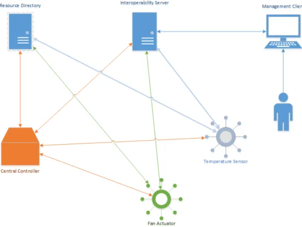
Earlier we discussed the different components of our semantic interoperability so-lution. In this section, we will discuss how all these components work together to provide a solution for the semantic interoperability problem. For a better under-standing of the process, we take an example of an IoT network as given in Figure 4.3.
In this example, we have a central controller that receive temperature data from a temperature sensor, and then send commands to a fan actuator to control the fan speed accordingly. The temperature sensor or fan actuator are constrained devices. Their resources are very limited and hence they usually do not provide meta-data about their output. In an IoT network, where numerous constrained devices from different manufacturers are connected to the network, there is a high probability of misunderstanding the semantics of output of these devices. A simple example of such a scenario would be multiple temperature sensors sending data to a central controller, where few temperature sensors use Fahrenheit as temperature unit and rest are using Celsius unit. Such a situation can easily lead to some unintended consequences causing semantic interoperability problem. In this section, we will
Figure 4.3 An IoT network using Interoperability Server and Resource Directory
demonstrate the working principles of our solution using the example given in Figure 4.3.
We divide the whole process into the following steps,
1. Temperature Sensor, Fan Actuator, and Central Controller registers their Thing Descriptions with Interoperability Server
2. Temperature Sensor and Fan Actuator registers their resources with Resource Directory
3. Central Controller query Resource Directory for a resource
4. Central Controller query Interoperability Server for semantic information about temperature resource
Now we have a high-level concept of how the Endpoints can make use of Interoper-ability Server to receive semantic information of the target resource. In the following sections, we will discuss each of the steps in detail.
4.5.1
Temperature Sensor, Fan Actuator, and Central
Con-troller registers their Thing Descriptions with
Interop-erability Server
The first step in the communication is that every endpoint is identified by a semantic ID. The semantic ID is a unique identifier allocated by the Interoperability Server to an endpoint upon registration of its Thing Description with Interoperability Server. The endpoint can register its Thing Description with the Interoperability Server by sending a POST request over IS Interface. Specifications of the POST request are defined in section 4.4.3. Example of such request is given in Figure 4.4
Figure 4.4 An example of the registration of the Thing Description with the Interoper-ability Server
The Figure 4.4 shows the output of the temperature sensor registration Thing De-scription registration request. The output has two import important things to no-tice. First, the CoAP 2.01 message for successful operation, second, a string output "/td/1831d3ad". The text string contains the Semantic ID "1831d3ad" of the tem-perature sensor. This string is also the path of Thing Description inside the Interop-erability Server. Using this path, we can create a URI to get the Thing Description
from the Interoperability Server (as shown in Figure4.4.3). Every Endpoint is re-quired to perform this procedure to get a Semantic ID. If the Endpoint does not have enough capabilities to do registration with Interoperability Server, an adminis-trator can add the corresponding endpoint Thing Description to the Interoperability Server to get a Semantic ID.
4.5.2
Temperature Sensor and Fan Actuator registers their
resources with Resource Directory
Next step in the communication is that the endpoints register their hosted resources with Resource Directory. Endpoint uses the Semantic ID for Uri-Query option "sem", in the registration message along with the other options as specified in section 4.4.2. An Example of a resource registration with Resource Directory is given in Figure 4.5.
Figure 4.5 An example of the registration of the temperature resource with the Resource Directory
The registration request in Figure 4.5 shows the output of a temperature resource registration request with Resource Directory. The response message indicates the re-turn code of "2.01 Create" i.e. the registration was successful. The important things to notice in POST request message are the Semantic ID, resource type, and path of the resource. If an Endpoint hosts more than one resource, the same Semantic ID will be used with all the resources
The same way every endpoint can register resources with Resource Directory. If the endpoint does not have capabilities to register resources with Resource Directory, a third party can also do the registration on behalf of an endpoint.