A University of Sussex DPhil thesis
Available
online
via
Sussex
Research
Online:
http://sro.sussex.ac.uk/
This
thesis
is
protected
by
copyright
which
belongs
to
the
author.
This
thesis
cannot
be
reproduced
or
quoted
extensively
from
without
first
obtaining
permission
in
writing
from
the
Author
The
content
must
not
be
changed
in
any
way
or
sold
commercially
in
any
format
or
medium
without
the
formal
permission
of
the
Author
When
referring
to
this
work,
full
bibliographic
details
including
the
author,
title,
awarding
institution
and
date
of
the
thesis
must
be
given
Numerical Simulations of Rotating
Stall in Axial Flow Compressors
Yan-Ling Li
Department of Engineering and Design
University of Sussex
A thesis submitted for the degree of
Doctor of Philosophy
Declaration
The work presented in this thesis is, to the best of the candidate’s knowledge and belief, original and the candidate’s own work, except as acknowledged in the text. The material has not been submitted, either in whole or in part, for a degree or comparable award of University of Sussex or any other university or institution.
Author
Yan-Ling Li Date
Yanling Li, Doctor of Philosophy
Numerical Simulations of Rotating Stall
in Axial Flow Compressors
Summary
Gas turbine compressor performance may encounter deterioration during service for various reasons such as damage by debris from the casing or foreign objects impacting on the blades, typically near the rotor’s tip. Moreover, mal-schedule of Variable Stator Vanes (VSVs) during start-up may also result in performance deterioration and reduction in the surge margin. Ability to assess the effect of compressor deterioration using Computational Fluid Dynamics (CFD) is important at both design stage and in service. Compressor blade damage breaks the cyclic symmetry and the VSVs mal-schecule creates mis-match between stages together with geometric variations, thus computations are desirable to be performed using full annulus assemblies. Furthermore, downstream boundary conditions are also unknown during rotating stall or surge and simulations become difficult.
This research presents unsteady time-accurate CFD analyses of compressor per-formance with tip curl blade damage in a single stage axial flow compressor and VSVs mal-schedule in a 3.5 stage axial flow compressor. Computations were per-formed near stall boundary to predict rotating stall characteristics. The primary objectives are to characterise the overall compressor performance and analyse the detailed flow behaviour. Computations for the nominal blade configurations were
iii
also performed for comparison purposes for both compressors. All unsteady simula-tions were performed at part speeds with a variable nozzle downstream representing an experimental throttle.
For the blade damage study, two different degrees of damage for one blade and multiple damaged blades were investigated and compared with the results from the undamaged case. For the VSVs mal-schedule study, the first two stators were as-sumed to be variable and were used to create mal-schedule vane settings for the investigation. The effects of blade damage and VSVs mal-schedule on the aerody-namics performance and rotating stall characteristics for both compressor assemblies were investigated respectively and discussed in detail.
Firstly, I would like to express my great gratitude to my principal supervisor Professor Abdulnaser Sayma for his technical and non-technical support throughout my time at University of Sussex. He substantially influenced the direction of my work and taught me so much during the many in-depth discussions, and also for being so understanding of my situation as an international student. I am extremely thankful, he continued to offer his support and encouragement during the final stage of this work, after he took up an academic post at City University London.
I would like to thank Dr Zhijun Peng as he kindly agreed to act as my official supervisor for a short period before he took up an academic post at University of Hertfordshire after Naser’s move. Thanks are due to Dr Zhiyin Yang who kindly agreed to act as my supervisor for the short period after Dr Peng’s move. Special thanks are due to Dr Herwart Honen from RWTH Aachen University for providing the IDAC compressor geometry and experimental data. I would like to thank Dr Shaobin Li who was a visiting fellow in 2011 at University of Sussex from Beihang University, China. He kindly provided the CFX steady state solutions of the IDAC compressor for the VSVs mal-schedule study in this research. He also provided very valuable discussions in compressor aerodynamics and CFD simulations.
I would like to thank Dr Xia Hao for valuable discussions we had about CFD simulations. Thanks are due to Dr Vasudevan Kanjirakkad with whom I had valu-able discussions about compressor aerodynamics and instabilities. I would also like to thank my colleague Mr Pascal Nucara for the interesting discussions we had and Mr Harri Koivisto a colleague who always gave me useful advice and support throughout my studies. Special thanks to all other staff in TFMRC who gave me non-academic support. The financial support of University of Sussex funding this project is gratefully acknowledged.
I would like to dedicate this thesis to my parents and friends who supported me in the long journey, especially for my father’s financial
Contents
Contents vi
List of Figures ix
List of Tables xvi
Nomenclature xix
1 Introduction 1
1.1 Background . . . 1
1.2 Objectives . . . 6
1.3 Contributions . . . 8
1.4 Structure of the thesis . . . 8
1.5 Publications . . . 9
2 Literature review 10 2.1 About this chapter . . . 10
2.2 Rotating stall studies . . . 10
2.2.1 Influencing factors . . . 11
2.2.2 Investigations of mechanisms of rotating stall . . . 16
2.3 Blade damage studies . . . 23
2.4 Variable Stator Vanes studies . . . 24
vii CONTENTS
3 Numerical method and validation 28
3.1 About this chapter . . . 28
3.2 Flow model . . . 28
3.2.1 Governing equations . . . 28
3.2.2 Numerical discretisation . . . 31
3.3 Description of the rotor . . . 34
3.4 Boundary conditions . . . 34
3.5 Grid independence study . . . 36
3.6 Validation with experimental data and discussion . . . 44
3.7 Summary . . . 54
4 Rotating stall of a single stage axial flow compressor with nominal blade settings 56 4.1 About this chapter . . . 56
4.2 Computational domain and boundary conditions . . . 57
4.3 Unsteady simulation away from stall boundary . . . 60
4.4 Unsteady simulation near stall boundary . . . 63
4.5 Summary . . . 74
5 Blade damage effects on compressor performance 76 5.1 About this chapter . . . 76
5.2 Computational geometry . . . 76
5.3 Unsteady simulation away from stall boundary with one damaged blade 79 5.4 Effects of different degrees of damage of one blade . . . 80
5.5 Effects of multiple damaged blades . . . 91
5.6 Summary . . . 96
6 VSVs mal-schedule effects on a 3.5 stage axial flow compressor 99 6.1 About this chapter . . . 99
6.2 Description of the compressor . . . 99
6.4 Study of rotating stall indicators . . . 102
6.5 Unsteady investigation for the Nominal case near stall boundary . . . 118
6.6 Investigation with VSVs mal-schedule . . . 124
6.6.1 Flow in IGV and stage 1 . . . 126
6.6.2 Flow in stage 2 . . . 133
6.6.3 Flow in stage 3 . . . 135
6.7 Summary . . . 143
7 Conclusions and recommendations 145 7.1 Main findings of the blade damage study . . . 146
7.2 Main findings of the VSVs mal-schedule study . . . 148
7.3 Recommendations for future work . . . 149
ix LIST OF FIGURES
List of Figures
1.1 Axial flow compressor characteristics at given rotational speeds (NASA
Rotor 37) . . . 2
1.2 Propagation of rotating stall in NASA Rotor 37 . . . 4
3.1 Typical 2D control volume . . . 32
3.2 View of one Rotor 37 blade . . . 35
3.3 Typical mesh for Rotor 37 . . . 36
3.4 Geometry demonstration for single passage steady state analysis . . . 36
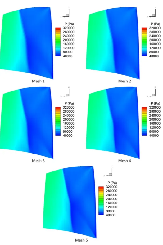
3.5 Mesh comparison in the blade to blade direction . . . 37
3.6 Mach Number Contour Comparison at 95% span . . . 39
3.7 Mach Number Contour Comparison at 90% span . . . 40
3.8 Mach Number Contour Comparison at 50% span . . . 41
3.9 Pressure Contour Comparison on the suction side of the blade . . . . 42
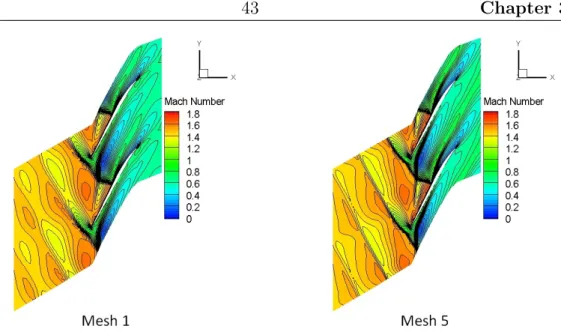
3.10 Mach Number Contour Comparison at 95% span at near stall condition 43 3.11 Pressure profile comparison at 95% span . . . 45
3.12 Pressure profile comparison at 90% span . . . 46
3.13 Pressure profile comparison at 50% span . . . 47
3.14 Radial distribution of circumferentially averaged pressure and tem-perature ratios at downstream of the rotor . . . 48
3.15 Comparisons of Overall Characteristics with Experimental Data (Left to right: 60% speed, 80% speed and 100% speed) . . . 50
3.16 Contours of Mach number in a blade-to-blade view along the 95% span at high flow condition for design speed(Measured data is from
Suder [1997]) . . . 51
3.17 Contours of Mach number in a blade-to-blade view along the 95% span at low flow condition for design speed(Measured data is from Suder [1997]) . . . 52
3.18 Contours of Mach number in a blade-to-blade view along the 70% span at low flow condition for design speed(Measured data is from Suder [1997]) . . . 53
3.19 Comparisons of Radial Flow Characteristics . . . 55
4.1 Computational geometry for unsteady simulation . . . 57
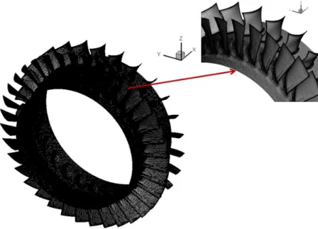
4.2 Partial view of the mesh used for full annulus simulations . . . 58
4.3 Steady state solution at 60% of rotor speed . . . 60
4.4 Circumferential positions of numerical sensors . . . 61
4.5 Unsteady static pressure history at the inlet of rotor without rotating stall . . . 62
4.6 Fourier Transform components from one of the numerical sensors . . . 63
4.7 Pressure profiles comparison between steady and time averaged un-steady solution . . . 64
4.8 Instantaneous static pressure contour plot at the upstream of the rotor 65 4.9 Instantaneous axial velocity contour plot near the tip surface of the rotor . . . 65
4.10 Instantaneous streamline structure inside the rotor . . . 66
4.11 Compressor performance during rotating stall . . . 67
4.12 Circumferentially averaged axial velocity profile comparison at the downstream of Rotor 37 . . . 68
4.13 Mach number contour comparison at 75% span of Rotor 37 . . . 68
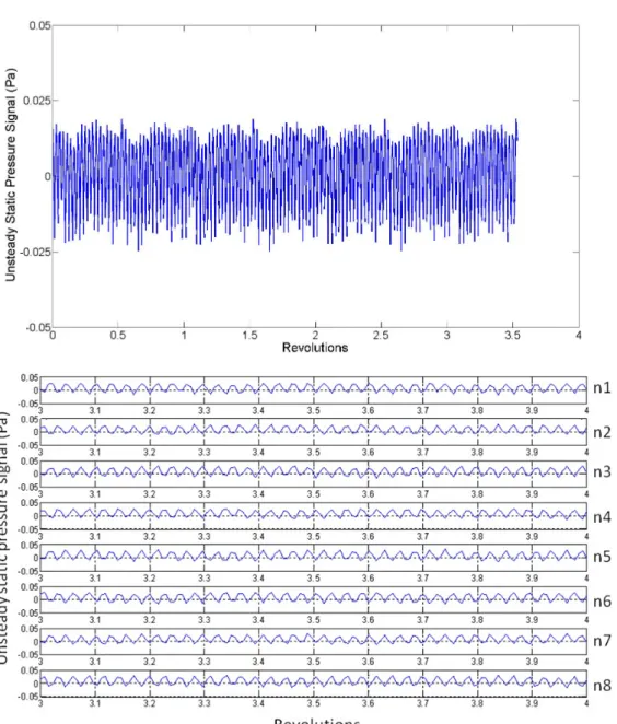
4.14 Unsteady static pressure signal full time history from numerical sen-sors on the casing . . . 69
xi LIST OF FIGURES
4.15 Unsteady static pressure signal from numerical sensor 1 on the casing
in one rotor revolution . . . 70
4.16 Fourier Transform components from numerical sensor 1 . . . 70
4.17 Development of rotating stall cells . . . 72
4.18 Instantaneous negative axial velocity on an axial cut plane . . . 73
4.19 3D streamline inside the stall cell . . . 74
5.1 Partial view of mesh used for unsteady computation with one medium damaged blade . . . 77
5.2 Views of damaged blades . . . 78
5.3 Circumferentially averaged axial velocity profile comparison away from stall boundary . . . 80
5.4 Unsteady static pressure history at the inlet of rotor without rotating stall . . . 81
5.5 Instantaneous axial velocity on an axial cut plane upstream the rotor 82 5.6 Instantaneous axial velocity at 95% of rotor span . . . 82
5.7 Compressor performance during rotating stall . . . 83
5.8 Circumferentially averaged axial velocity profile comparison at the downstream of Rotor 37 . . . 85
5.9 Unsteady static pressure full time history comparison (Up: Damage Case 1, Down: Damage Case 2) . . . 86
5.10 Unsteady static pressure time history comparison in one rotor revo-lution (Up: Damage Case 1, Down: Damage Case 2) . . . 87
5.11 Fourier transform components of numerical sensor 8 on the casing for Damage Case 1 . . . 88
5.12 Fourier transform components of numerical sensor 8 on the casing for Damage Case 2 . . . 89
5.13 Instantaneous negative velocity near the tip of the rotor . . . 90
5.14 Instantaneous negative velocity comparison on an axial cut plane . . 90
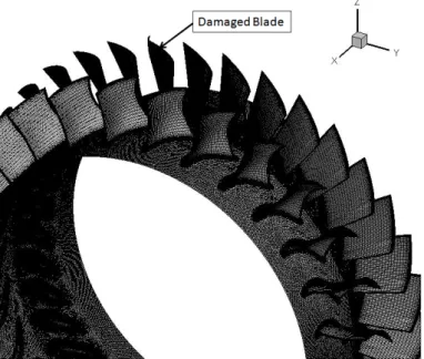
5.16 Part of the rotor assembly for Damage Case 3 . . . 92 5.17 Compressor performance for Damage Case 3 . . . 93 5.18 Circumferentially averaged axial velocity profile comparison at the
downstream of Rotor 37 . . . 94 5.19 Mach number contour plot comparison at 75% span of Rotor 37 . . . 94 5.20 Unsteady static pressure signal time history from numerical sensors
on the casing(Up: Time history in last 10 revolutions; down: Time history in 1 revolution) . . . 95
5.21 Instantaneous negative axial velocity near the tip of the rotor . . . . 96
5.22 Instantaneous negative axial velocity on an axial cut plane through rotor blade . . . 97
6.1 View of IDAC compressor . . . 100
6.2 View of computational domain of IDAC compressor for unsteady
sim-ulations . . . 103
6.3 Mesh view for rotor 1 . . . 103
6.4 IDAC characteristics at three different speeds (Higher mass flow to
lower mass flow: 100% speed, 84% speed and 68% speed) . . . 104
6.5 Stage performance characteristics at three different speeds (Low mass
flow to high mass flow: 68% speed, 84% speed and 100% speed) . . . 107
6.6 Blade profile comparison at mid span . . . 108
6.7 Overall compressor performance comparison at 68% speed . . . 109
6.8 Mach number contour plot near the hub of the blades at near stall
point at 68% speed (Upper: Nominal case; Lower: MS case) . . . 111
6.9 Mach number contour plot at the mid-span of the blades at near stall
point at 68% speed (Upper: Nominal case; Lower: MS case) . . . 112 6.10 Mach number contour plot near the tip of the blades at near stall
point at 68% speed (Upper: Nominal case;Lower:MS case) . . . 113 6.11 Pressure profile comparison on S1 at mid span . . . 114 6.12 Pressure profile comparison on R2 at mid span . . . 115
xiii LIST OF FIGURES
6.13 Pressure profile comparison on S2 at mid span . . . 115
6.14 Pressure profile comparison on R3 at mid span . . . 116
6.15 Pressure profile comparison on S3 at mid span . . . 116
6.16 Axial velocity radial profile comparison upstream of S1 . . . 117
6.17 Axial velocity radial profile comparison upstream of S2 . . . 117
6.18 Overall compressor performance during surge with steady state solution120 6.19 Mass flow time history for the Nominal case . . . 120
6.20 Unsteady static pressure signal time history from eight numerical sensors on the casing upstream R1 for Nominal case . . . 122
6.21 Fourier transform components from one sensor upstream R1 . . . 122
6.22 Unsteady static pressure signal time history from six numerical sen-sors on the casing in different axial locations for Nominal case(D: downstream; U: upstream) . . . 123
6.23 Instantaneous circumferentially averaged axial velocity radial profile upstream of S3 . . . 124
6.24 Overall compressor perfomance during rotating stall with steady state solution . . . 125
6.25 Mass flow time history for VSVs mal-schedule case . . . 126
6.26 Instantaneous negative axial velocity contour plot at 95% of blade span after 30 revolutions . . . 127
6.27 Unsteady static pressure signal time history from numerical sensors at the inlet of R1 for the MS case . . . 128
6.28 Fourier Transform Components from one of the numerical sensor at the inlet of R1 for case with VSVs mal-schedule . . . 128
6.29 Instantaneous axial velocity in the middle of IGVs after 30 rev for MS case . . . 129
6.30 Instantaneous negative axial velocity on axial cut planes near the leading edge of R1 at different time frames for MS case . . . 130
6.31 Instantaneous negative axial velocity on an axial cut plane in the middle of R1 at different time frames for MS case . . . 131 6.32 Instantaneous negative axial velocity on an axial cut plane near the
trailing edge of R1 at different time frames for MS case . . . 132 6.33 Axial velocity on an axial cut plane in the middle of S1 after 30 rev
for MS case . . . 132 6.34 Unsteady static pressure signal time history from numerical sensor at
the inlet of R2 for case with VSVs mal-schedule . . . 133 6.35 Fourier Transform Components from one of the numerical sensor at
the inlet of R2 for MS case . . . 134 6.36 Instantaneous negative axial velocity contour plot on an axial cut
plane near the leading edge of R2 at different time frames for the MS
case . . . 135
6.37 Instantaneous negative axial velocity contour plot on an axial cut plane in the middle of R2 at different time frames for the MS case . . 136 6.38 Instantaneous negative axial velocity contour plot on an axial cut
plane near the trailing edge of R2 at different time frames for the MS
case . . . 137
6.39 Instantaneous axial velocity contour plot in the middle of S2 after 30 rev for the MS case . . . 137 6.40 Unsteady static pressure signal time history from numerical sensor at
the inlet of R3 for case with VSVs mal-schedule . . . 138 6.41 Fourier Transform Components from one of the numerical sensor at
the inlet of R3 for case with VSVs mal-schedule . . . 139 6.42 Instantaneous negative axial velocity on the axial plane near the
lead-ing edge of R3 at different time frames for the MS case . . . 140 6.43 Instantaneous negative axial velocity on the axial plane in the middle
xv LIST OF FIGURES
6.44 Instantaneous negative axial velocity on the axial plane near the trail-ing edge of R3 at different time frames for the MS case . . . 142 6.45 Negative axial velocity on the axial plane in the middle S3 after 30
List of Tables
3.1 Specifications of Rotor 37 . . . 35
3.2 Overall performance comparisons for different grids . . . 38
6.1 Specifications of IDAC Compressor . . . 101
xvii Nomenclature
Nomenclature
Greek Symbols
∆τ pseudo-time step
Γ boundary of the control volume
γ constant specific heat ratio
µ total viscosity of the fluid
Ω control volume
ω rotational speed of rotor bladerow
ρ fluid density
σ viscous stress tensor
Subscripts
δij Kronecker delta function
µl molecular viscosity
µt turbulent eddy viscosity
ΩI area of the control volume constructed by connecting the dual median
of the cells surrounding nodeI
I,J1,...,Jn node index in the mesh
P rl laminar Prandtl number
P rt turbulent Prandtl number
Bi boundary integral
FIJS inviscid fluxes along side IJS
GIJS viscid fluxes along side IJS
SI rotational source term at nodeI
Uτ pseudo-time derivative term
UI solution vector at node I
ηIJS side weight
Other Symbols
e specific total energy of the fluid
H total enthalpy of the fluid
n time level
p pressure of the fluid
x rotational axis of the compressor
F inviscid flux vector
G viscous term
n outward normal unit vector of the control volume boundary Γ
S source term
U conservative variable
xix Nomenclature
v fluid velocity in the relative frame of reference
Acronyms / Abbreviations
CDA controlled diffusion airfoils
CFD computational fluid dynamics
DES detached eddy simulation
FOD foreign object damage
IDAC inversely designed Aachen compressor
IP intermediate pressure
LES large eddy simulation
MCA multiple circular arc
OGV outlet guide vane
PR total pressure ratio
RANS Reynolds-Averaged Navier-Stokes
RWTH Rheinisch-Westfalische Technische Hochschule
TFMRC Thermo-Fluid Research Centre
TR total temperature ratio
URANS unsteady Reynolds-Averaged Navier-Stokes
Chapter 1
Introduction
1.1
Background
Axial flow compressors are the principal type of compressors commonly used in gas turbines for aircraft and power generation. To meet the needs of gas turbines, the demanding requirements of axial flow compressors are high efficiency, high flow capacity within a relatively small structure, high pressure ratio, reasonable manu-facturing costs, robustness and reliability. For a compressor in service, it is found to be difficult to maintain the originally designed aerodynamic performance when de-terioration occurs (Levine [1998]). Compressor performance plays an important role in gas turbine engines. Any change could influence the efficiency and power output both of which are essential factors. It is normally characterised by a map in the form of pressure rise versus mass flow function as partially shown in Figure 1.1. The operating range of the compressor is bounded by the choke and surge boundaries as seen from the figure. It is well known that the region between the working line and surge line is defined as surge margin. Flow under most of the operating conditions on the map is normally steady, in the rotor’s frame of reference, and axisymmetric. As seen in Figure 1.1, the characteristic curve tends to be vertical at high flow, indicating the maximum mass flow going into the compressor which is also known as the choke boundary; at low flow, it tends to be more horizontal, indicating the maximum pressure rise with minimum mass flow in the compressor which is also
2 Chapter 1
Figure 1.1: Axial flow compressor characteristics at given rotational speeds (NASA Rotor 37)
known as the surge boundary. When compressors operate near the surge boundary, mass flow is reduced and excessive positive incidences on the rotor blades occur. When the incidence reaches a critical value, instability may be encountered in the form of flow separation. If the situation becomes worse, it may lead to surge. Surge limits the maximum pressure ratio and minimum flow conditions for stable opera-tion. It is a global phenomenon which is normally characterised by large mass flow rate fluctuation or flow reversal. There are two types of surge commonly reported in the literature: classic surge and deep surge. Classic surge normally occurs with large oscillation of mass flow being pressurised and unpressurised periodically. The latter one, deep surge, is a more severe phenomenon possibly with flow reversal. Deep surge is also typically manifested by high abnormal noise or flames reaching the inlet; in which case leading to compressor destruction as reported by Levine [1998]. More details regarding the classification of surge can be referred to Greitzer [1981] and de Jager [1995]. The degree of stability of the compressor is represented by the slope of the characteristic curve. As the slope of the tangent line of the curve tends to be zero, compressor stability diminishes and the flow tends to be unstable and the chance for surge increases.
Another phenomenon compressors normally encounter, rotating stall, will be the focus of this study. Rotating stall is normally found at compressor part-speeds dur-ing start-up process. It is normally the precursor of surge and the compressor could be in operation with rotating stall if a new equilibrium for the flow can be estab-lished. However, it is frequently accompanied with pulsating loads and extra blade vibrations due to stall cells rotating around the annulus. At extreme conditions, this can lead to component failure. Compared to surge, rotating stall is a localised phenomenon to a particular rotor or particular stages in which a compressor could operate without failure and may recover from. It commonly consists of one or more stall cells covering one or more blade passages that propagate in the same direction of the rotor rotation at some fraction of the shaft speed. The number of stall cells and the propagation speed may vary at different operating conditions in different compressors, but typically, the propagation speed is around half of the shaft speed. The mechanisms of rotating stall initiation and its characteristics are still the subject of continuous scientific debate; however, for clarity it may be explained by reference to Figure 1.2. A localised flow perturbation could cause blade 2 to encounter higher positive incidence more than the neighbouring blades and the flow separates on its suction side lead to the formation of a stall cell which reduces the flow passing into the passage above that blade. This may occur either due to the impurity of the inflow, manufacturing tolerance or different numbers of blades in each bladerow. Then the blocked flow diverts flow around the blade so that the incidence increases on blade 1 and decreases on blade 3. This leads to the stall cell moving to the passage above blade 1. At a subsequent time, due to blockage above blade 1, blade 2 encounters lower positive incidence leading to the recovery of the passage above, while blade 1 will have higher positive incidence leading to stall in the passage above. This is the start of propagation of stall cells around the annulus. Therefore, a very strong reason to avoid rotating stall is the consequent blade excitation which may lead to high cycle fatigue damage as claimed by Walsh and Fletcher [2004].
4 Chapter 1
Figure 1.2: Propagation of rotating stall in NASA Rotor 37
As discussed above, surge and rotating stall are two common instability phenom-ena which compressors could encounter when they operate close to the surge line. There are various reasons which may cause compressor instabilities, for instance engine deterioration or Foreign Object Damage (FOD). Surge could be initiated from stall of compressor blades. Stall of compressor blades is caused by the flow separations on the suction sides of blades as mentioned above. When blades stall, flow through the compressor is blocked and becomes unstable. When the condition becomes worse, it may lead to a situation that the compressor can no longer provide pressure rise as expected. When the compressor reaches the deep surge condition, the compressed high-pressure reversal flow behind the stall goes forward through the compressor and out from the inlet. The whole process is usually fast, rapid and often quite audible along with a ‘bang noise’ in the engine. Engine surge can be accompanied by a visible flash forward out from the inlet.
Based on its characteristic on the compressor map, stall can be classified into two categories as reported by Gong [1999]: progressive or abrupt stall. For progressive stall, pressure ratio will drop gradually by reducing the mass flow. Rotating stall occurring consequently is normally formed of more than one stall cell in part span
pattern in the radial direction. On the other hand abrupt stall normally results from a discontinuous drop in pressure ratio and efficiency. Rotating stall observed in this case normally consisted of one single cell in full span pattern in the radial direction. Based on inception condition, it has been observed that rotating stall can be initiated by two types of inception: the long length-scale or modal type and the short length-scale or spike type, which was reported by Camp and Day [1998]. They could be distinguished by the type of initial perturbation in static pressure or velocity signal. Modal inception normally has a small amplitude disturbance with long wavelength seen in the pressure/velocity time histories and needs a large number of revolutions to develop. With modal inception, stall cells can rotate at 30% to 50% of rotor speed. Spike inception normally has larger amplitudes in the initial perturbation with a propagation speed of stall cells at 70% to 80% of the rotor speed (Vo et al. [2008]).
As mentioned above, rotating stall could result from or be affected by compressor deterioration. Although investigations on rotating stall drew attention since the 1950’s and a lot of work in this area has been done so far, surge and/or rotating stall continue to occur for the reasons listed below which are not exhaustive (Levine [1998]):
• Rotating stall due to Inlet Guide Vanes (IGV), Variable Stator Vanes (VSVs)
and bleed valves that do not operate properly during start-up.
• Surge or stall due to deterioration of the compressor condition such as fouling,
erosion and roughness.
• Surge or stall due to deterioration of the compressor condition such as blade
damage caused by ice or foreign object injection.
• Surge due to operation beyond the recommended operating limits.
As a result of the limited time scale in this research, only blade damage effects and the effects of VSVs mal-schedule were investigated.
6 Chapter 1
Compressor blades may encounter damage during service for various reasons such as loose casing liner, Foreign Object Damage (FOD) or ice formation at the intake. FOD from other sources, such as tire fragments, injection of bird (bird strike) and runaway debris or animals, may also be encountered. This may result in deterioration of the compressor performance and in extreme conditions, may cause compressor stall or surge. During the design process, it is important to be able to predict the aerodynamic behaviour of the compressor in such events to enable the design of robust blades capable of coping with these events.
During start-up process, the flow may pass through the regions of potential stall and beyond surge margin. For multi-stage compressors, flow condition is controlled during start-up by using Variable Inlet Guide Vanes (VIGVs) or VSVs and/or bleed valves to avoid compressor instabilities. By changing VSVs settings, it allows com-pressors to operate in a safe region on its characteristic map without stall or surge. In detail, during the start-up process, the flow density is low in the rear stages, resulting in a mismatch of the aerodynamic design which needs to avoid stall at all speeds. To overcome this mismatch, VSVs are commonly used to reduce the air flow at low speeds and thereby reduce the flow velocities in the rear stages to avoid stall and surge (Levine [1998]). Approaching the design point, VSVs are opened to allow more flow in to achieve the expected mass flow. Normally, the design schedule of VSVs is a function of corrected engine speed at different shaft speeds and ensure the compressor is operating near the peak efficiency region (Campbell [1958]). However, improper settings and malfunction of VSVs systems could lead to rotating stall or surge. The malfunction operation of VSVs will be termed as mal-schedule of VSVs in this thesis.
1.2
Objectives
In this thesis, issues regarding the effects of blade damage and mal-schedule of VSVs were investigated. As explained in the previous section, bird strikes or ice ingestion and FOD are common issues which could happen in aero engines. They may also
cause fan or compressor blade damage which may initiate rotating stall or surge. Although there were investigations published on blade damage effects on compressor performance, the influences from aerodynamics point of view have been overlooked. Meanwhile, VSVs are commonly used in front stages in multi-stage compressors. The control mechanism of VSVs may malfunction in some circumferences which could change the performance completely. There are very few investigations regarding the effects of VSVs mal-schedule on compressor aerodynamics and rotating stall characteristics. Therefore, the specific objectives in this research are:
1. To gain a fundamental understanding of the impact of blade damage on a single stage axial flow compressor aerodynamic performance and its rotating stall characteristics at off-design condition, in particular:
• To investigate compressor performance and rotating stall characteristics
with nominal blade settings.
• To investigate effects of different degrees of one damaged blade on
com-pressor performance and rotating stall characteristics.
• To investigate effects of multiple damaged blades on compressor
perfor-mance and rotating stall characteristics.
2. To investigate the effects of VSVs mal-schedule on the performance of a multi-stage axial flow compressor and its rotating stall characteristics, in particular:
• To investigate whether steady state solutions close to stall boundary have
precursors for potential stall.
• To characterise compressor performance near stall boundary with
nomi-nal blade settings.
• To investigate compressor performance at near stall boundary with VSVs
mal-schedule which might provide information regarding the resilience of the compressor.
8 Chapter 1
1.3
Contributions
The key contributions of this thesis are:
• Most of the work related to blade damage in the literature was performed on
fan blades and/or investigations from aeroelasticity point of view. The effects on compressor aerodynamics performance and rotating stall characteristics
have been overlooked. This thesis presents the first account of impact of
compressor rotor blade damage on compressor aerodynamics performance and rotating stall characteristics. It was found that compressor assemblies with mild damage on the blade(s) do not have significant effects on the overall performance.
• There are very few studies regarding VSVs mal-schedule effects on compressor
performance, as reviewed in Chapter 2. This thesis presents one of the first few accounts of the effects of VSVs mal-schedule on compressor aerodynamics performance and rotating stall characteristics, to improve understanding of the problem. It seemed that the assembly with VSVs mal-schedule was more stable than the one with nominal blade settings based on available data which do not represent the general case and requires further investigation.
1.4
Structure of the thesis
This thesis is divided into seven chapters, including this one which provides the background information and objectives of this research. A literature review will be presented in Chapter 2. Studies including experimental and numerical (mainly CFD related) on rotating stall have been reviewed. The physical mechanisms behind rotating stall of both modal and spike inception as proposed will be summarised as well. In chapter 3, the numerical methodology used in this research will be described and validated using a transonic axial flow compressor. Grid independence study has been also investigated to determine the suitable meshes for code validation and
unsteady analyses to compromise the accuracy of the solution and computing time needed.
The thesis consists of two main parts. The first part, the blade damage study, will be presented in Chapters 4 and 5. Before discussing blade damage effect near stall boundary, it is better to have the understanding of the flow behaviour without any damaged blade. Therefore, in Chapter 4, the unsteady simulation with nominal blade settings near stall boundary will be presented first. Then, in Chapter 5, the blade damage effects will be analysed, including different degrees of one damaged blade and multiple damaged blades with identical degree of damage. The second part of the thesis, VSVs mal-schedule effects, will be presented in Chapter 6. Two cases are compared in order to investigate the VSVs mal-schedule effect: compressor assemblies with nominal blade settings and VSVs mal-schedule. Finally, Chapter 7 summarises the main findings and the outcomes of this research. Suggestions for future work will then be provided based on the discussion and analyses from the results obtained.
1.5
Publications
Selected parts of this thesis have been published which is listed as the following paper:
• Part of the blade damage study was presented at the conference of ASME
Turbo Expo 2012, Copenhagen, Denmark, 11-15 June 2012 (Li and Sayma [2012]).
• Part of the VSVs mal-schedule study was accepted for the conference of ASME
Turbo Expo 2014, Dusseldorf, Germany, 16-20 June 2014 (Li and Sayma [2014]).
10
Chapter 2
Literature review
2.1
About this chapter
In this chapter, literature which is relevant to the objectives of this research will be reviewed. Firstly, studies including experimental and numerical (mainly CFD related) on rotating stall have been summarised. Both influencing factors which may cause rotating stall and investigations regarding the mechanisms of rotating stall are presented. Secondly, reviews of blade damage studies and VSVs studies are given separately. At the end, concluding remarks regarding the reviewed literatures are presented.
2.2
Rotating stall studies
There are two main routes for rotating stall studies in the literature: experimental and numerical, both will be included in this chapter. Within numerical studies, there are two commonly used methods: Computational Fluid Dynamics (CFD) and analytical method. In the past two decades CFD has become popular for the following reasons: 1) Full scale experiments are normally difficult and extremely expensive to perform; 2) Experiments are not possible at the design stage; 3) CFD could provide the flow details within the computational domain which may lead to a better understanding of the flow behaviour. Reviews on numerical work will be
focusing on CFD related issues which are relevant to this research. Thus, the relevant analytical work could be referred to Longley [1994], Greitzer [1976], Moore and Greitzer [1986], Greitzer and Moore [1986] and Abed et al. [1991] which will not be reviewed in this chapter. The review of experimental work provides understanding of the physics of the phenomenon. Although the work in this research is investigated using CFD, it is also worthwhile to understand rotating stall through experimental investigations. Rotating stall is observed either when the compressor operates close to stall boundary at specific rotational speed or it is caused by other features in the compressor such as inflow with foreign object injection.
Theoretically, studies on rotating stall could be divided into three aspects: 1) inception; 2) development; 3) fully developed pattern. Studies on rotating stall in-ception aim at finding the working mechanism and causes for rotating stall initiation. It is also important to find the indicators for rotating stall to help developing active control system for its avoidance. For information about rotating stall avoidance which is not the concern of this research, one can refer to the techniques on early stall warnings such as the work done by Tahara et al. [2004]; and stall detection systems, design of control or avoidance systems are also beyond the scope of this research. More information can be found in Bindl et al. [2009], Feulner et al. [1996], Schulze and Hennechke [1998] and Christensen et al. [2008].
In the next subsection, influencing factors or possible causes which could be responsible for rotating stall will be presented. Previous efforts which resulted in better understanding of the mechanisms of rotating stall are discussed afterwards.
2.2.1
Influencing factors
The early rotating stall studies date back to the 1950’s. One of the early experiments was performed by Benser [1953] in a high pressure ratio multi-stage compressor at Lewis Flight Propulsion Laboratory. Part span rotating stall was observed. Results showed that the influence from stage interaction could result in performance discon-tinuities in later stages when rotating stall was observed in the inlet stage. Since
12 Chapter 2
then, a large amount of work has been done such as rotating stall inception, criteria for two different types of rotating stall inception, flow behaviour during rotating stall and rotating stall avoidance or recovery systems. Despite that, the mechanisms of rotating stall are still with lack of understanding.
Rotating stall is commonly observed at lower rotational speeds (Lewis et al. [1954]) and is generally three dimensional in nature (Beknev et al. [1973]). That indicates 3D numerical simulations are necessary. A 3D unsteady Euler equations based solver was used by Nakano et al. [1999] because it was not possible to ap-ply 3D unsteady Navier-stokes solver within the whole flow regions in multi-stage compressors with the capability of supercomputers at that time. Simulations were conducted at 100% speed to match the condition for the available experimental data. Results had a good agreement with the experimental data for the 6-stage transonic compressor. The 3D calculation was performed on the 3-stage transonic compressor and spike type disturbance was predicted as in the experiment. Results showed that three-dimensional simulations were necessary when rotating stall was initiated by short length scale disturbances.
Rotating stall is a very complex phenomenon because it could be affected by many factors. The testing environment is one factor which has significant effect on rotating stall characteristics. An experiment was carried out by Longley and Hynes [1990] using a refurbished C106 compressor at the Whittle Laboratory Cambridge University. The experiment aimed at finding out how much the compressor perfor-mance (characteristics) including stall was affected by the testing environment. A compressor stage was tested operating separately and also as a part of the whole compression system. Results showed that when the compressor stage operated both separately and with two identical downstream stages, the pressure ratio character-istic rise monotonically until stall; while when the compressor stages operated with two mismatched downstream stages, instability occurred at a much lower pressure ratio and mass flow. They also found out that the stall characteristic of a stage was affected by the whole compression system in multi-stage compressors. Therefore,
the rotating stall characteristic in an isolated rotor is different from the one when the rotor is part of the multi-stage compressor which indicates that to accurately in-vestigate rotating stall in multi-stage compressors, a model of the whole compression system is desirable.
For isolated rotor stage test rigs, rotating stall is not only relying on the specifi-cations of the rotor, but also the stator vanes located downstream. An experiment was carried out by Montgomery and Braun [1957] in a single stage compressor. Ro-tating stall was observed both with and without stator blades. With stator blades, it was found that there was less stall cells observed and rotating stall tended to occur at a higher mass flow. Thus, the stator used downstream would influence the rotating stall characteristics.
Another factor which may influence rotating stall is the stator/rotor gap. An experiment in a low speed compressor was conducted by Inoue et al. [2002]. The rotating stall process was similar for a large gap and a mild gap: first spike type rotating stall was observed and then it turned into modal wave rotating stall. For the small gap, it was initiated with modal wave rotating stall and then spike type rotating stall was observed; eventually it was formed to be a modal wave stall cell.
Boundary layers also have influence on rotating stall characteristics. As pro-posed by Lakhwani [1973], different boundary layers on the casing would lead to different stall patterns in an isolated rotor bladerow test rig. When the casing wall boundary layer was increased, rotating stall took place at higher mass flow rate and it was highly likely to obtain a progressive type stall. It was also found that the entry boundary layer thickness had no effect on the propagation speed of rotating stall. Choi et al. [2008] investigated the effects of inlet boundary layer thickness on rotating stall in an axial subsonic compressor using a three-dimensional numerical simulation. The in-house code is based on compressible Reynolds-Averaged Navier-Stokes (RANS) equations. The unsteady simulation was performed on a sector of the annulus which was two sevenths of total blade passages with 4.2 million nodes. It was found that the inlet boundary layer thickness had obvious effect on both the
14 Chapter 2
flow coefficient at stall inception and the size of the rotating stall cell.
Rotating stall could be affected by the operating conditions as well, such as the rotational speed. A Rolls Royce VIPER Mk522 was tested by Freeman [1992] to study the inception of stall at a range of speeds and analyse the post stall behaviour. Part-span rotating stall was found when the compressor was operating at or below 62% of design speed and front stages were severely stalled. A 3D RANS code was used by Cai et al. [2004] to investigate rotating stall in a low speed fan. Results showed that the propagation speed of rotating stall cells depends on the compres-sor operating speed. Spanwise contour plots showed the flow detail which agrees with the experimental data. That also demonstrated the capability of accurately modelling rotating stall using CFD.
The effects of fan speed on rotating inception was also investigated by Choi et al. [2011] in an axial flow fan using an implicit, time-accurate 3D compressible RANS solver. The computational domain was simulated in a full annulus fashion at 70%, 80% and 90% speed. The fan speed was found to be a critical factor to determine the final pattern of rotating stall. When the fan speed was increased, the number of rotating stall cells was reduced and their size enlarged while the propagation speed was reduced. They reported that the flow incidence difference at different fan speed could be the reason for the different flow patterns.
Stall inception was investigated in full-scale engine tests by Hoss et al. [2000]. The engine used is a two-spool turbofan engine. Different types of stall precursor were found at different shaft speeds: spike-type at low speed and modal wave at mid-speed. At higher speeds, the rotor shaft imbalance was found to be the key to the stall inception.
Another factor that could be responsible for rotating stall is the radial loading distribution of rotor blades. The relevant effect on the stall inception pattern was investigated experimentally by Nie [2003] using a single stage low speed compres-sor. With low loading distributions near the tip regions, modal stall inception was observed; while high loading distributions near the tip regions would lead to spike
type inception. They also found that loading distributions near the hub regions had no effects on the stall inception pattern.
Effects of radial loadings on stall inceptions in a low speed compressor were also numerically and experimentally investigated by Zhang et al. [2009a]. Results showed that different radial loadings had significant effects on the stall limit. The compressor became more unstable when the distortion was closer to the blade tip. The position of radial distortion would lead to different rotating stall characteristics: hub distortion to modal inception rotating stall while centre and tip distortion to spike inception rotating stall.
Inflow conditions could also contribute to rotating stall inception. Experimental investigations on fourteen different stages from low speed compressor were performed by Cyrus [2000]. It was found that the rotor bladerow played the main role on the inception of rotating stall; and the onset was also affected by the stage inlet flow condition. Inlet distortion was also proved to be one of the causes of rotating stall by Lin et al. [2005] and Jiang et al. [2009]. The role of tip leakage flow under inlet distortion to trigger rotating stall was investigated by Zhang et al. [2009b]. It was also found that tip clearance flow played an important role in the development of stall regions near the casing in most of the cases. Due to the rotor-stator interaction influence, separations were also found in the stator bladerow near the casing. This also showed that stator downstream could influence the rotating stall characteristics. Another important influencing factor is the tip clearance flow. The interaction of tip clearance flow with flow in adjacent blades could be one of the causes which lead to rotating stall as reported by Mailach et al. [2001]. A full annulus 3D time-accurate simulation was conducted on a compressor by Hah and Rabe [2001]. They found that rotating stall may be caused by the interaction of tip clearance vortex and passage shock. The role of tip clearance flow on stall inception was also numerically and experimentally investigated by Bennington and Du [2010] using a transonic compressor. It was believed by the authors that their work was also the validation for the spike inception criteria proposed by Vo et al. [2008]. The criteria related to
16 Chapter 2
the role of tip clearance flow will be summarised in the next subsection.
The relationship between unsteady behaviour of tip leakage vortex and a rotating disturbance was numerically investigated by Yamada et al. [2008]. The simulation was performed on one ninth of the whole annulus with about 5.4 million points. Rotating disturbances were predicted to be initiated by the fluctuation of tip leakage flow in the rotor.
Flow injection can also contribute to inception of rotating stall. A time-accurate CFD code was used to simulate the stall inception in the compression system of the T700 engine used in Army Blackhawk Helicopeter in the US by Hathaway et al. [2004]. In that study a high speed compressor was investigated. The simulation used three bladerows which consist of an injector, a rotor and a stator bladerow. Two conditions were studied: one with injection and the other without injection. Stall inception was predicted under injection condition. With an injection of 5.9% of the design mass flow (20.34 kg/s), the results showed it can stabilise the unstable flow which may be responsible for the stall inception. Results showed that injection was one effective way to avoid rotating stall under certain conditions.
To sum up, rotating stall is three dimensional in nature and could depend on the testing environment, casing boundary layer thickness, operating condition such as rotational speed, radial loading distributions on rotor blades, inlet distortion, tip clearance flow and flow injection. Those made the phenomenon more complicated and less understood. In the next section, efforts which have been made to get better understanding of the mechanisms behind rotating stall will be presented.
2.2.2
Investigations of mechanisms of rotating stall
Although rotating stall characteristics would be distinct with different operating conditions in different compressors and could be affected by many factors, Day [1993] proposed that there were two types of rotating stall based on its inception route: modal-wave and spike type initiation. They can be distinguished by the type of initial disturbances in the unsteady pressure or velocity signals. Modal
inception normally has a small amplitude disturbance with long wavelength seen in the pressure/velocity time histories and needs a large number of revolutions to develop. Spike inception normally has larger amplitudes with a propagation speed of 70-80% of the rotor speed. Compared to modal wave rotating stall, spike type rotating stall is less understood which is the reason that many efforts have been devoted to investigate the mechanisms behind it. In this subsection, previous work will be reviewed in historical order.
In a multi-stage compressor, spike inception was highly likely to be observed in the first rotor as reported by Longley et al. [1996]. Also in multi-stage compressors, when rotating stall was found in the front stage(s), it would act as an inlet rotating distortion for the downstream stages and could influence their stability. On the other hand, it also suggested that the testing environment was important for the formation of rotating stall.
The spike type rotating stall was investigated both experimentally and numer-ically by Hah et al. [1999]. An unsteady time-accurate three-dimensional viscous Navier-Stokes code was used for the numerical simulations. The computation was performed on the full annulus of a low speed compressor which contained about 1.7 million nodes. A standard two-equation turbulence model was applied. Spike type inception was predicted from the unsteady simulation which matched the experi-ment. The propagation speed of rotating stall was between 60% to 80% of rotor speed which requires more accurate prediction. Results showed that the inception was very similar to the one observed from the experiment.The role of the local flow structures on rotating stall inception was unknown including tip clearance flow based on the available data.
A 2D unsteady Navier-Stokes simulation was conducted by Outa et al. [1999] for a compressor cascade stage of rotor and stator to investigate the evolution of rotating stall under uniform inlet conditions. An implicit time-marching scheme was applied in the solver. The stator stalled first and led to the formation of stall cells in the rotor. Rotating stall cells were mainly contained in a vortex upstream the
18 Chapter 2
rotor and that caused a spike fluctuation in the inflow velocity. The limitation of 2D analysis was that the mass flow during rotating stall and stall cell from initial vortex were not correctly predicted. Also the 3D effects of the unsteady flow including tip clearance flow was excluded.
The propagation of spike type rotating stall cells in a low speed compressor was experimentally investigated by Inoue et al. [2000]. Under mild stall state, five rotating stall cells were observed with a rotating speed of approximately 72% of rotor speed. By throttling the compressor further, it turned to a modal wave with one large cell under deep stall condition with a rotating speed of 29% of rotor speed. The spike type rotating stall cell was formed a low pressure bubble with a leg travelling ahead of the rotor. The leg was linked to a blade suction surface while changing the blade in turn as the pressure bubble travelled. The mechanism was believed to be that the vortex leg broke down with the bubble and merged with a new one as it travelled.
Mechanisms of rotating instabilities in a low speed compressor was numerically and experimentally investigated by Marz et al. [2002]. The numerical simulation was performed on the full annulus of the compressor rotor without the downstream stator using a 3D time-accurate unsteady Navier-Stokes code. A modified two-equation turbulence model was used with wall function near the wall. The computational domain contained about 3.5 million nodes. Results showed that the code was able to capture similar flow behaviour as in the measurements. Results also showed that a rotating instability vortex was formed near the leading edge resulting from the interaction of tip clearance flow, axially reversed flow and the inflow. This was believed by the authors to be the precursor of the rotating stall.
Spike type rotating stall inception in a transonic compressor was experimentally investigated by Bergner et al. [2006]. When the compressor was operating near stall, unsteadiness showed a strong fluctuation of tip clearance flow; and the inception of rotating stall was believed to be initiated by the resulting spill forward of the tip clearance flow. The spike disturbances could be caused by the upstream motion
of one blade passages shock based on the available data. With the development of new techniques in experimental instrumentation, attempts have been made to investigate flow features inside rotating stall cells by Lepicovsky and Braunscheidel [2006]. Results showed that the measurement methodology used was capable to determine the unsteady flow parameters inside a rotating stall cell. It was also found that the compressor used which was operating at design speed had a rotating stall with one cell propagating at 50.6% of the rotor speed.
The stability of NASA Stage 35 was numerically investigated using a 3D unsteady CFD code by Chima [2006]. The code used is a multiblock Navier-Stokes solver which uses an explicit finite difference scheme. The Baldwin-Lomax turbulence model was used. Rotating stall with two part-span stall cells was observed from the unsteady simulation. It was shown that the code was capable of predicting rotating stall inception and its recovery. No detailed discussions regarding rotating characteristic and the relevant mechanism were provided.
A quasi 3D code based on solving the Navier-Stokes equations on stream surfaces was used by Gourdain et al. [2006a] to investigate rotating stall in an axial single stage low speed compressor. The Baldwin-Lomax turbulence model was used. Two rotating stall cells with a propagation speed of 48% of rotor speed were observed. Results showed that Baldwin-Lomax model could not predict the stability limit of the compressor accurately.
A full annulus unsteady 3D simulation was performed in a single stage low speed compressor by Gourdain et al. [2006b]. It was also validated by experimental mea-surements. The solver used solves the RANS equations using a finite volume method. The Sparlart-Allmaras turbulence model was used. The computational domain con-tained approximately 31 millions nodes. Two types of rotating stall were observed in this compressor stage with the same throttle parameter. The first was caused by the interaction between the tip clearance flow, in-passage separation vortex at mid-span and inflow. It had a propagation speed of 75% of the rotor speed. The second was the modal wave rotating stall which was observed later. The stall point
20 Chapter 2
matched well with experiment, but the number of stall cells was not well predicted. An experimental study of rotating stall inception was performed in a single stage low speed compressor by Simpson and Longley [2007]. Results showed that spike type inception could be correlated to the incidence in the tip region of the rotor blade. Both rotor geometry and the flow around it will determine the critical incidence for rotating stall inception.
Full annulus CFD simulations of pre-stall behaviour using NASA Stage 35 was performed by Chen et al. [2007] using high-performance parallel computations. The
solver uses the unsteady Navier-Stokes equations with decoupled k- turbulence
model. The computational domain contained about 67 million points and simula-tions were performed on an IBM P4 cluster using 328 CPUs for 24 hours. Spike type inception was predicted. The spike was caused by the interaction between the tip clearance vortex and the dual-shock flow structure in the passage. That study also demonstrated the capability of CFD methods to investigate this type of flow problems.
Criteria for spike type rotating stall were firstly proposed by Vo et al. [2008]. One criterion is that the interface between the tip clearance flow and the inflow becomes parallel to the leading edge plane of the rotor. The other one is the flow through some passages turns into the adjacent passages at the trailing edge of the blades. The work showed that their hypothesis agreed with all published observations of this type of rotating stall initiation in axial flow compressors at that time.
An investigation using Large Eddy Simulation (LES) was performed on a sin-gle passage model by Hah [2009] to investigate the mechanisms behind the spike type rotating stall inception in a transonic compressor. Their reason to use LES was to capture unsteady flow features which can not be accurately computed by RANS model. Non-reflecting boundary conditions were applied at the inlet and the exit boundaries. They found that when the compressor operated at the near stall condition, the unsteadiness was caused by the interaction between the tip clear-ance vortices and the in-passage shock. That also confirmed the theory proposed
by Bergner et al. [2006] which was also believed by the authors to be the natural phenomenon in a transonic compressor. When the in-passage shocks were fully de-tached from the leading edge, spike type rotating stall started. Results from LES simulations showed that flow features obtained were more close to the real flow physics for the single passage simulations. The numerical simulations agreed well with the measurements for the circumferential size of the rotating stall cell and its propagation speed. Due to the limitations of single passage simulations, it was not possible to know the number of rotating stall cells and their distributions.
An experimental investigation was conducted using the Notre Dame Transonic Axial Compressor by Bennington and Du [2010]. An interface between the tip-leakage flow and the incoming axial flow was observed. When the compressor was operating at near stall condition, that interface moved upstream and when it reached the leading edge of the rotor rotating stall was initiated. That confirmed the proposal by Vo et al. [2008].
Stall inception in a two-stage low-speed compressor was numerically and ex-perimentally investigated by Tu et al. [2010] using 3D unsteady computations. The solver is based on dimensional unsteady Euler equations and the three-dimensional multi actuator-disks model. The simulation was performed on full an-nulus geometry. Results showed that stall cells were firstly observed in the second stage and the propagation speed of the fully developed stall cells were about 40.4% of rotor speed which agreed with the experimental data. However, the type of ro-tating stall could not be determined with the available data since the development of rotating stall happened within very short time according to the authors.
Rotating stall was simulated in the full annulus of a compressor stage using an URANS code by Gourdain et al. [2010]. The Spalart-Allmaras turbulence model was used because it was shown to be capable of providing a good compromise between cost and accuracy. By comparing with experimental data, it showed that the code was capable of predicting the phenomenon of spike type rotating stall. However, the number of rotating stall cells and their propagation speed were not correctly
pre-22 Chapter 2
dicted. Also the development process was quite different which also needed further improvement on the code or inlet boundary conditions. That could be because the inlet boundary conditions for experiment were not well known and were different from the simulation.
The full annulus of an isolated rotor was numerically and experimentally inves-tigated by Wu et al. [2011]. The solver is based on URANS methods. The Spalart-Allmaras was employed to calculate the eddy viscosity. The negative slope near stall boundary from the computational results indicated that spike type rotating stall inception could be encountered and that was also proved by the experimental data. The unsteady simulation also showed that spike type rotating stall was ob-served. It propagated at approximately 33.3% of rotor speed which matched with the experimental data. Each stall cell covered approximately 2-3 rotor pitches in the circumferential direction and less than 30% span in the radial direction. Features of rotating stall cell in both the circumferential and radial directions agreed well with the experimental data.
Numerical stall simulations were validated by Choi et al. [2011b] with experimen-tal data at 60% and 95% of the shaft speed in a modern transonic fan. An implicit, time-accurate 3D compressible RANS solver was used. The numerical study was based on 3D unsteady full annulus simulations. When a fully developed spike ini-tiated rotating stall was obtained in the simulation, solutions of mass flow rate, number of rotating stall cell and their propagation speed were well matched with the experimental data. It provided the confidence in using CFD simulations in this type of flows.
Detailed experimental measurements of spike-type rotating stall inception were presented by Weichert and Day [2012]. The measurements were done in a single stage compressor at the Whittle Laboratory Cambridge University. It was found that a radial vortex was involved in the spike inception. It also showed that with the development of instrumentation techniques experiments could reveal the flow better in the three dimensional sense which provides very good validation data for
CFD solutions. However, this type of measurements are still very expensive. Pullan et al. [2012] tried to describe the evolution from spike inception to rotating stall and to explain the physical mechanism behind them from numerical simulations. Simulations were performed by using an unsteady RANS code with one-equation
Spalart-Allmaras turbulence model. NASA E3 rotor was used in their simulations.
It was performed in 2D and 3D full annulus with and without tip clearance. All cases have similar general features that spikes were formed from flow separation near the blade leading edge on the suction side. It was also found that radial vortex was involved in the spike formation. The comparisons of all solutions and also with experimental data suggested that the spike formation did not necessarily depend on tip leakage flow in their cases.
The unsteady behaviour and three-dimensional flow structure spike-type stall inception in a low-speed compressor rotor was numerically and experimentally inves-tigated by Yamada et al. [2012]. The in-house code solves 3D compressible Navier-Stokes equations using Detached Eddy Simulation (DES) for flow modelling. The numerical solutions showed that the spike disturbance was caused by a vortex which was caused by the separation at the leading edge near the rotor tip.
2.3
Blade damage studies
A literature search showed that there are very few published research work about flow behaviour in blade damaged compressors. Most of the available material con-cerns about fan blades damaged by bird strike. Bird impact analysis on aeroengine fan blades was investigated by Audic et al. [1999] without analyses of aerodynam-ics performance. A 3D simulation of a bird-damaged aero-engine fan assembly was investigated by Kim et al. [2001]. The fan assembly had two blades with different degrees of damage. The simulations were performed at two points on the compressor characteristic map which were at higher mass flow/lower pressure ratio and at lower mass flow/higher pressure ratio respectively. It was found that flutter stability was reduced and stall was observed at higher mass flow compared to the undamaged
24 Chapter 2
fan.
Another investigation by Frischbier and Kraus [2005] using advanced numerical methods was reported on bird ingestion in a multiple stage turbofan. However, the results showed that the model had a considerable loss of accuracy with the mass flow of the low pressure compressor. Recent studies using the commercial code ANSYS/LS-DYNA by Meguid et al. [2008] and Guan et al. [2008] were about analysis of structural deformation of fan blades caused by bird strikes and no aero-dynamics studies were attempted.
A study of the performance, forced response and surge caused by ice-damaged blades in Intermediate Pressure (IP) compressor assemblies were investigated by Dhandapani et al. [2008]. Results showed that surge margin was reduced by in-creasing the number of damaged blades and the severity of performance degradation depended on both the number of damaged blades and their distributions around the annulus. However, no information about unsteady flow simulation was presented in their paper.
An aerodynamics study of bird strike using NASA Rotor 67 was investigated by Bohari and Sayma [2010] using Computational Fluid Dynamics (CFD). Two damaged assemblies were simulated at different rotational speeds. It was found that the surge margin has deteriorated at higher rotational speeds and stall was found before the working line for both assemblies. No unsteady time accurate simulations for rotating stall were attempted.
2.4
Variable Stator Vanes studies
For given Variable Stator Vanes (VSVs) in a specific compressor, there is a limit of varying the range for their scheduling. In the XJ79-GE-1 turbojet engine, it was found by Campbell [1958] that when VSVs were closed halfway, the peak compressor efficiency was reduced by 0.02%. However, if the VSVs were further closed, the peak compressor efficiency would drop sharply. The net thrust was affected by closing VSVs slightly. While the specific fuel consumption can be only affected when VSVs
were closed more than halfway with significantly reduced compressor peak efficiency. Kau [1998] proposed that the challenge of the VSVs system was the positional accuracy and hysteresis. And VSVs fault can be manual errors caused by installation and mal-function of the control system. Work has been done on fault diagnosis of VSVs system by Muir et al. [1989], Eustace et al. [1994], Merrington [1994] and
Stamatic et al. [1990]. All of those works were focused on the development of
techniques used to identify VSVs system fault without analyses of their effects on compressor aerodynamics effects.
Goebel et al. [2004] investigated few faults including sensor faults and actuator faults where an actuator was used to control the schedule of VSVs system. In their paper, those faults were chosen to be tested for general diagnostic techniques. It was found that if the VSVs failed in a fully open condition, the engine could not maintain its operability. If the VSVs failed in an inter-medium condition, the operation condition could be changed to cope with the situation which may keep the operability of the engine.
A 3D viscous time-accurate flow solver was used to model rotating stall and surge by Vahdati et al. [2008]. A variable-area nozzle was used at the back instead of a fixed back pressure. This model can simulate the steady flow near stall and can also represent a simplified axial surge event. It allows a total flow reversal. In the rotating stall case, rotating stall was induced by geometrically mis-tuning the rotor blade. The first three bladerows have variable-angle vanes using datum and mal-scheduled vane settings. The front nine bladerows were modelled in a whole-annulus fashion and the rest bladerows were modelled in a single passage fashion. It has a grid of 60 million points. After 13th revolutions, the variation of the static pressure upstream of rotor 1 showed that rotating stall was observed for the mal-scheduled case. There were about 10 to 13 rotating stall cells.
Effect of VSVs schedule on rotating stall inception in multi-stage compressor at part speed was numerically investigated by Peng [2011]. An eight-stage compressor was chosen for this study. VSVs were located at the front three stages. Spike type
![Figure 3.16: Contours of Mach number in a blade-to-blade view along the 95% span at high flow condition for design speed(Measured data is from Suder [1997])](https://thumb-us.123doks.com/thumbv2/123dok_us/1877335.2774074/72.892.296.704.128.1056/figure-contours-mach-number-condition-design-measured-suder.webp)
![Figure 3.17: Contours of Mach number in a blade-to-blade view along the 95% span at low flow condition for design speed(Measured data is from Suder [1997])](https://thumb-us.123doks.com/thumbv2/123dok_us/1877335.2774074/73.892.305.674.120.1048/figure-contours-mach-number-condition-design-measured-suder.webp)