A generic model for representing software development
methods.
WONG, Alan C.Y.
Available from Sheffield Hallam University Research Archive (SHURA) at: http://shura.shu.ac.uk/20559/
This document is the author deposited version. You are advised to consult the publisher's version if you wish to cite from it.
Published version
WONG, Alan C.Y. (1996). A generic model for representing software development methods. Doctoral, Sheffield Hallam University (United Kingdom)..
Copyright and re-use policy
See http://shura.shu.ac.uk/information.html
3
1 01 522 987 5
Fines are charged at 50p per hour
2 4 APR 2002
ProQuest Number: 10701206
All rights reserved
INFORMATION TO ALL USERS
The quality of this reproduction is dependent upon the quality of the copy submitted.
In the unlikely event that the author did not send a com plete manuscript and there are missing pages, these will be noted. Also, if material had to be removed,
a note will indicate the deletion.
uest
ProQuest 10701206
Published by ProQuest LLC(2017). Copyright of the Dissertation is held by the Author.
All rights reserved.
This work is protected against unauthorized copying under Title 17, United States C ode Microform Edition © ProQuest LLC.
ProQuest LLC.
789 East Eisenhower Parkway P.O. Box 1346
A Generic Model for Representing
Software Development Methods
Alan C.Y. WONG
A thesis submitted in partial fulfilment of the requirements
Sheffield Hallam University
for the degree of Doctor of Philosophy
ABSTRACT
ACKNOWLEDGMENTS
TABLE OF CONTENTS
PAGE
ABSTRACT
i
ACKNOWLEDGEMENT
ii
TABLE OF CONTENTS
iii
TABLE OF FIGURES
xii
TABLE OF TABLES
xvii
1. INTRODUCTION
1.1
1.1 INTRODUCTION 1.1
1.1.1 Background 1.1
1.1.2 History of Software Engineering 1.2
1.1.3 Managing Complexity of Software Engineering 1.3
1.2 THE REAL PROBLEMS 1.4
1.2.1 Panacea Syndrome 1.4
1.2.2 Looking Under the Lamppost Syndrome 1.5
1.2.3 Three Blind Men Touching an Elephant Syndrome 1.6
1.3 THE PROPOSED SOLUTION 1.7
1.4 EPISTEMOLOGICAL HIERARCHY OF KNOWLEDGE 1.8
1.5 ROAD MAP 1.10
1.6 CONCLUSION 1.12
2. INVESTIGATION OF SOFTWARE DEVELOPMENT
2.1
METHODS
2.1 INTRODUCTION 2.1
2.2 STRUCTURED METHODS 2.3
2.2.1 DeMarco Structured Analysis (DeMarco SA) 2.3
2.2.2 Jackson Structured Design (JSD) 2.4
2.2.3 Yourdon Modern Structured Analysis (Yourdon) 2.5
I able oj contents
2.3 OBJECT-ORIENTED METHODS 2.7
2.3.1 Object-Oriented Structured Design (OOSD) 2.8
2.3.2 Object-Oriented System Analysis (OOSA) 2.9
2.3.3 Object-Oriented Analysis/Design (OOA/OOD) 2.10
2.3.4 Nielsen Object-Oriented Design (Nielsen OOD) 2.11
2.3.5 Object-Oriented Software Engineering (OOSE) 2.12
2.4 CHOSEN METHODS 2.13
2.4.1 Booch Object-Oriented Design (Booch OOD) 2.14
2.4.2 Hierarchical Object-Oriented Design (HOOD) 2.16
2.4.3 Object Modelling Technique (OMT) 2.18
2.4.4 Ptech 2.20
2.4.5 Codarts/DA 2.22
2.5 OTHER METHODS 2.25
2.5.1 Class, Responsibility and Collaboration (CRC) 2.25
2.5.2 ASTS Development Method 3 (ADM3) 2.26
2.5.3 The Fusion Method (Fusion) 2.27
2.5.4 The KADS Method 2.29
2.6 SUMMARY OF INVESTIGATION 2.31
2.7 CONCLUSION 2.32
3. INVESTIGATION OF METHOD INTEGRATION, META
3.1
MODELLING RESEARCH AND METACASE TOOLS
3.1 INTRODUCTION 3.1
3.2 METHOD INTEGRATION 3.2
3.2.1 CASE Data Interchange Format (CDIF) 3.2
3.2.2 Portable Common Tool Environment (PCTE) 3.3
3.3 META MODELLING RESEARCHES 3.5
3.3.1 ALF-MASP 3.5
3.3.2 SOCRATES Project 3.9
3.3.3 MethodBase 3.12
3.4 METACASE TOOLS 3.16
3.4.1 ObjectMaker 3.16
3.4.2 MetaEdit 3.18
3.5 SUMMARY OF INVESTIGATION 3.6 CONCLUSION
4. SEMANTIC KNOWLEDGE BASE
4.1 INTRODUCTION
4.2 EVOLUTION APPROACH 4.2.1 Traditional Approach 4.2.2 Prototyping Approach
4.2.3 Method Engineering Approach
4.2.3.1 Requirement Specification Prototyping 4.2.3.2 Methodology Prototyping
4.2.3.3 Software Development Prototyping 4.3 THREE LAYERED MODEL
4.4 SINGLE METHODOLOGY MODEL 4.5 KNOWLEDGE BASE REPRESENTATION 4.6 METHODOLOGY PROTOTYPING
4.6.1 Method Controller
4.6.2 Canonical Concept Dictionary 4.6.3 System References
4.7 CONCLUSION
5. PRODUCT MODEL
5.1 INTRODUCTION 5.2 AIMS & OBJECTIVES 5.3 CONCEPT MODELLING
5.3.1 Concept Types
5.3.1.1 Entity Concept 5.3.1.2 Fragment Concept 5.3.1.3 Property Concept 5.3.1.4 Link Concept 5.3.1.5 Group Concept
5.3.2 Concept Relationship Properties 5.3.2.1 Cardinality
i aoie oj moments
5.3.2.4 Role 5.7
5.3.2.5 Overlapping and Completeness Features 5.8
5.3.2.6 Constraint Rule 5.9
5.3.3 Concept Relationships 5.11
5.3.3.1 Subtyping 5.11
5.3.3.2 Composition 5.12
5.3.3.3 Linking 5.13
5.3.3.4 Grouping 5.15
5.3.3.5 Referencing 5.17
5.4 ADVANCED CONCEPT MODELLING 5.19
5.4.1 Aggregation vs Decomposition vs Referencing 5.19
5.4.2 Composition vs Referencing 5.20
5.4.3 Merging Source and Target Links 5.21
5.4.4 Overriding 5.21
5.4.5 Inclusion and Exclusion 5.22
5.5 PROCESS MODEL OF PRODUCT MODEL 5.24
5.6 ZOOM HIERARCHY 5.29
5.6.1 Zoom by Detail 5.29
5.6.2 Zoom by Feature 5.30
5.7 PRODUCT MODEL OF CONCEPT DIAGRAM 5.30
5.8 CONCLUSION 5.32
6. PROCESS MODEL
6.1
6.1 INTRODUCTION 6.1
6.2 META MODELLING PROCESSES 6.2
6.2.1 Method Process 6.3
6.2.2 MetaCASE Process 6.4
6.2.3 CASE Tool Process 6.5
6.3 BASIC ISSUES 6.6
6.4 THREE PRELIMINARY APPROACHES 6.7
6.4.1 Menu Driven Approach 6.7
6.4.2 Event Sequence Approach 6.8
6.4.3 Frame Based Navigation Approach 6.9
laoie oj moments
6.5.1 perform Function 6.11
6.5.2 do Function 6.11
6.5.3 draw Function 6.12
6.5.4 insert Function 6.12
6.5.5 delete Function 6.12
6.5.6 modify Function 6.12
6.5.7 adjust Function 6.13
6.5.8 retype Function 6.13
6.5.9 specify Function 6.13
6.6 TASK SEQUENCE 6.14
6.7 TASK MODELLING 6.16
6.7.1 A Task 6.16
6.7.2 Task Trigger and Concept Flow 6.17
6.7.3 Task Diagram 6.19
6.7.4 Task Decomposition 6.19
6.7.5 Task Refinement 6.20
6.7.6 Parallel Tasks 6.21
6.8 META PROCESS MODEL 6.22
6.9 META META MODEL 6.23
6.10 CONCLUSION 6.26
7. HEURISTIC MODEL
7.1
7.1 INTRODUCTION 7.1
7.2 METHOD HEURISTIC 7.2
7.2.1 Concept Heuristic 7.2
7.2.2 Task Heuristic 7.3
7.3 HEURISTIC TEXT 7.4
7.4 HEURISTIC RULE 7.5
7.5 HEURISTIC LINK 7.6
7.5.1 Composition Link 7.7
7.5.2 Reference Link 7.8
7.6 MAPPING TO THE TWO MODELS 7.9
7.7 CONCLUSION 7.10
Table oj contents
8.1 INTRODUCTION 8.1
8.2 OVERVIEW OF GMR REPRESENTATION 8.2
8.3 ADDITIONAL CONSIDERATIONS 8.3
8.3.1 Dissection Set 8.3
8.3.2 Shared Concept 8.5
8.3.3 Other Relationships 8.7
8.3.3.1 Derived Relationship 8.7
8.3.3.2 Multiple Inheritance 8.8
5.3.3.3 Delegation 8.9
8.3.4 Text Fragment 8.9
8.4 METHOD SPECIFICATION LANGUAGE 8.11
8.5 PROLOG CLAUSE FORMAT 8.14
8.6 CONCLUSION 8.16
9. METHOD EVALUATION
9.1
9.1 INTRODUCTION 9.1
9.2 FRAGMENT DISSECTION 9.1
9.2.1 Product Dissection 9.2
9.2.2 Process Dissection 9.5
9.3 METHOD COMPARISON 9.9
9.3.1 Numerical Comparison 9.10
9.3.2 Fragment Comparison 9.13
9.4 SELECTION OF METHOD 9.15
9.5 CONCLUSION 9.16
10. KNOWLEDGE ACQUISITION OF METHOD MODELS
10.1
10.1 INTRODUCTION 10.1
10.2 METHOD KNOWLEDGE ACQUISITION 10.2
10.2.1 Knowledge Acquisition Problems 10.2
10.2.2 Knowledge Acquisition Techniques 10.3
10.3 KNOWLEDGE ACQUISITION MEDIA 10.4
10.3.1 Advantages of Method Acquisition Media 10.6
10.3.2 Disadvantages of Method Acquisition Media 10.6
10.4 ELICITATION OF METHOD KNOWLEDGE 10.7
Table of contents
10.4.1.1 Cursory Reading 10.9
10.4.1.2 Chronic Reading 10.11
10.4.1.3 Conclusive Reading 10.12
10.4.2 Method Knowledge Fabrication 10.13
10.4.3 Method Knowledge Verification 10.14
10.4.3.1 Correctness 10.15
10.4.3.2 Completeness 10.15
10.4.3.3 Contradiction 10.16
10.4.3.4 Consistency 10.16
10.4.3.5 Contrast 10.16
10.5 METHOD MODEL ELICITATION 10.17
10.5.1 Product Model Elicitation 10.17
10.5.2 Process Model Elicitation 10.18
10.5.3 Heuristic Model Elicitation 10.19
10.6 CONCLUSION 10.20
11. MAPPING METHOD SEMANTICS TO METACASE TOOLS
11.1
11.1 INTRODUCTION 11.1
11.2 SIGNIFICANCE OF METACASE TECHNOLOGY 11.3
11.2.1 Incremental Equilibrium in Method Engineering 11.3
11.2.2 Method Engineering in MetaCASE 11.4
11.2.3 Two CASE Studies 11.4
11.3 CASE STUDY A - SCRATCH METHOD 11.6
11.3.1 Product Model Mapping 11.6
11.3.1.1 Basic Product Mapping 11.7
11.3.1.2 Mapping Method Specific Semantics 11.8
11.3.1.3 Extra Semantics 11.11
11.3.2 Process Model Mapping 11.14
11.3.2.1 Basic Process Mapping 11.14
11.3.2.2 Five Steps Mapping Approach 11.15
11.3.2.3 Mapping Concept Dependence to Process Routes 11.19
11.3.3 Heuristic Model Mapping 11.20
11.3.4 More Points on Mapping Semantics 11.22
i aoie oj moments
11.4.1 Product Model Matching 11.23
11.4.2 Process Model Matching 11.26
11.4.3 Heuristic Model Matching 11.29
11.5 CONCLUSION 11.30
12. CONCLUSION
12.1
12.1 INTRODUCTION 12.1
12.2 CURRENT ACHIEVEMENT 12.2
12.3 FUTURE WORK 12.4
12.4 CONCLUSION 12.5
APPENDIX A. GLOSSARY
A.l
APPENDIX B. IPSYS TOOLBUILDER
B.l
B.l Toolset Architecture B.l
B.2 Entity Model B.2
B.3 Frame Model B.7
B.4 Shape Model B.10
APPENDIX C. THE KADS AND MIKE METHODOLOGIES
C.l
C.1 The KADS Methodology C.l
C.2 The MIKE Methodology C.9
APPENDIX D. CONCEPT DIAGRAMS
D.l
D.l HOOD Concept Diagram D.l
D.2 Booch OOD Concept Diagram D.2
D.3 Codarts/DA Concept Diagram D.3
D.4 OMT Concept Diagram D.4
D.5 Ptech Concept Diagram D.5
APPENDIX E. OMT TASK DIAGRAMS
E.l
E.1 OMT: Top Level Task Diagram and objectModelling Decomposition E .l
E.2 OMT: perform(identifyClass) Task Diagram E .l
E.3 OMT: perform(identifyAssociation) Task Diagram E.2
E.4 OMT: perform(identifyAttribute) Task Diagram E.2
i u u i c u j x ^ u n tc/**o
E.6 OMT: perform(verifyObjectModel) Task Diagram E.3
E.7 OMT: do(checkClass) Task Diagram E.3
E.8 OMT: do(checkAssociation) Task Diagram E.4
E.9 OMT: do(checkAttribute) Task Diagram E.4
APPENDIX F. OMT MSL STATEMENTS
F.l
APPENDIX G. OMT PROLOG CLAUSES
G.l
TABLE OF FIGURES
PAGE
Figure 1.1 A Generic View of Software Engineering 1.2
Figure 1.2 Epistemological Knowledge Hierarchy 1.9
Figure 1.3 Road Map of This Thesis 1.10
Figure 2.1 DeMarco Structured Analysis 2.3
Figure 2.2 JSP Structure Diagrams and Structure Text 2.4
Figure 2.3 Yourdon Modern Structured Analysis Tools 2.5
Figure 2.4 Introduction to SSADM 2.6
Figure 2.5 OOSD Notations 2.8
Figure 2.6 OOSA Models for a One-Minute Microwave Oven 2.9
Figure 2.7 Coad/Yourdon OOA Notations 2.10
Figure 2.8 Nielsen OOD Notations 2.11
Figure 2.9 Jacobson OOSE Notations 2.12
Figure 2.10 Booch OOD Models and Process 2.14
Figure 2.11 Booch Class Diagram and Object Diagram Notations 2.15
Figure 2.12 HOOD Notations 2.17
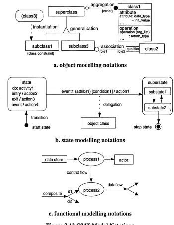
Figure 2.13 OMT Model Notations 2.19
Figure 2.14 Ptech Notations 2.21
Figure 2.15 Codarts/DA Notations 2.24
Figure 2.16 Codarts/DA Cruise Control Device I/O 2.24
Figure 2.17 CRC: ATM Graphs 2.25
Figure 2.18 ADM3 Icons for Interaction Diagram 2.27
Figure 2.19 Influences on the Fusion Method 2.28
Figure 2.20 Class Description 2.28
Figure 3.1 CDIF Standards 3.2
Figure 3.2 PCTE Standards 3.3
Figure 3.3 MASP Specification 3.6
Figure 3.4 ALF-MASP Approach 3.7
Figure 3.5 SOCRATES Three Levels of Abstraction 3.9
Figure 3.6 SOCRATES Concept Structure 3.10
i upie oj r igures
Figure 3.8 MethodBase Architecture 3.13
Figure 3.9 MethodBase Description of OOA 3.14
Figure 3.10 MetaEdit Approach 3.18
Figure 3.11 MetaEdit OPRR Modelling 3.19
Figure 3.12 OPRR Specification of DFD 3.20
Figure 4.1 Traditional Software Development Approach 4.3
Figure 4.2 Prototyping Approach 4.4
Figure 4.3 Three Stages Prototyping Approach 4.5
Figure 4.4 Three Levels of Software Development 4.8
Figure 4.5 Semantic Knowledge Base 4.9
Figure 4.6 Proposed Methodology Prototyping 4.12
Figure 5.1 OMT: concepts in a stateDiagram 5.4
Figure 5.2 OMT: splittingControl Grouping Cardinalities 5.7
Figure 5.3 Bi- and Uni- Directional Relationships in process 5.7 Figure 5.4 Examples of Overlapping and Completeness Features 5.8
Figure 5.5 A Simple dataFlowDiagram Product Model 5.9
Figure 5.6 HOOD: objectType Subtyping 5.10
Figure 5.7 OMT: state and transition Subtyping 5.11
Figure 5.8 OMT: state-action Compositions in stateDiagram 5.12
Figure 5.9 Composition Cardinalities 5.13
Figure 5.10 A Simple stateTransitionDiagram Example 5.14
Figure 5.11 OMT: transition Links in stateDiagram 5.14
Figure 5.12 OMT: nestedStateDiagram Grouping 5.15
Figure 5.13 OMT: splittingControl and mergingControl Grouping 5.16 Figure 5.14 Ptech: product and activity Decompositions 5.16
Figure 5.15 OMT: Referencing between Three Fragments 5.17
Figure 5.16 OMT: Bidirectional Referencing Relationships 5.17
Figure 5.17 Concept Diagram Notations 5.18
Figure 5.18 Aggregation vs Decomposition vs Referencing 5.19
Figure 5.19 Composition vs Referencing 5.20
Figure 5.20 Merged Link between interstate and transition 5.21 Figure 5.21 OMT: instantiation Concept Overrides the Superconcept Relationship 5.21
Figure 5.22 Four Cases of Possible Confusions 5.22
laoie ojrigures
Figure 5.24 Example of Cut Operations 5.23
Figure 5.25 IPSYS ToolBuilder Notation for Resolving Cut Operation 5.24
Figure 5.26 Step One: Fragment Concepts 5.25
Figure 5.27 OMT: Notation for state and transition Properties 5.26
Figure 5.28 Step Four: Properties of Existing Concepts 5.26
Figure 5.29 Step Five: Complex Grouping 5.27
Figure 5.30 Final Step: a Complete Product Model of stateDiagram 5.28
Figure 5.31 Codarts/DA: Overview Mode 5.29
Figure 5.32 Product Model of Concept Diagram 5.31
Figure 6.1 Meta Modelling Processes 6.2
Figure 6.2 IPSYS ToolBuilder: An Example of MetaCASE Process 6.4
Figure 6.3 Booch OOD: the Configurable Process 6.5
Figure 6.4 Menu Driven Approach 6.7
Figure 6.5 Event Sequence Approach 6.8
Figure 6.6 Frame Based Navigation Approach 6.9
Figure 6.7 Behaviour of Task Functions 6.10
Figure 6.8 Process Model: Task 6.16
Figure 6.9 Ptech: Trigger Rule 6.17
Figure 6.10 Process Model: Task Trigger and Concept Flow 6.18
Figure 6.11 OMT: dynamicModel Task Diagram 6.19
Figure 6.12 OMT: draw(stateDiagram) Task Diagram 6.20
Figure 6.13 OMT: do(verifyAssociation) Task Diagram 6.20
Figure 6.14 OMT: Parallel Tasks in Identifying Elements 6.21
Figure 6.15 Step 2: OMT dynamicModel Task Sequence 6.22
Figure 6.16 Task Diagram of Product Model 6.24
Figure 6.17 Concept Diagram of Process Model 6.25
Figure 6.18 Task Diagram of Process Model 6.25
Figure 7.1 OMT: Heuristic Network 7.6
Figure 7.2 Codarts/DA: objectStructuringCriteria Composition Link 7.7 Figure 7.3 Codarts/DA: taskCohesionCriteria and tasklnversionCriteria 7.7
Figure 7.4 Codarts/DA: Reference Link offunctionalCohesion 7.8
Figure 8.1 Method Development by GMR 8.2 Figure 8.2 Codarts/DA: dataFlow and dataTransformation Concepts 8.3
Figure 8.3 Codarts/DA: Dissection Sets 8.4
Figure 8.4 HOOD: constrainedOperation Shared Concept 8.5
Figure 8.5 Common Concepts between Fragments 8.6
Figure 8.6 OMT: Derived Relationship 8.7
Figure 8.7 Multiple Inheritance 8.8
Figure 8.8 Actor Delegation 8.9
Figure 8.9 HOOD: Relationships Between Graphical and Textual Fragments 8.10
Figure 8.10 BNF Definition of MSL 8.12-8.13
Figure 9.1 Method Product Dissection 9.3
Figure 9.2 OMT: Product Fragment Dissection 9.4
Figure 9.3 Ptech: Product Fragment Dissection 9.4
Figure 9.4 Simple Process Dissections 9.6
Figure 9.5 Codarts/DA: Process Model 9.8
Figure 9.6 Booch OOD: Process Model 9.9
Figure 10.1 General Approach for Knowledge Acquisition 10.4
Figure 10.2 Specific Approach for Method Knowledge Acquisition 10.6
Figure 10.3 Top Level Process Model for Method Elicitation 10.7
Figure 10.4 Method Knowledge Inspection 10.8
Figure 10.5 Method Knowledge Fabrication 10.13
Figure 10.6 Method Knowledge Verification 10.14
Figure 11.1 Two Ways of Modelling Method in MetaCASE Technology 11.2
Figure 11.2 Reflective Equilibrium in Inductive Inference 11.3
Figure 11.3 Incremental Equilibrium in Method Engineering 11.3
Figure 11.4 Semantic Gap in Method Engineering 11.4
Figure 11.5 Work-Flows of The Two CASE Studies 11.5
Figure 11.6 Concept Diagram for Scratch 11.6
Figure 11.7 ToolBuilder Entity Model Diagram for Sratch 11.9
Figure 11.8 ToolBuilder Entity Model of the startState to stop State Constraint 11.11
Figure 11.9 Task Diagram for Sratch Method 11.15
Figure 11.10 Creation Paths of Scratch Method Entities 11.16
Figure 11.11 ToolBuilder Navigation Model for Scratch 11.17
laoie oj rigures
Figure 11.13 Frame Based ToolBuilder Entity Model of Booch91 11.24
Figure 11.14 Booch91 Navigation Model in ToolBuilder 11.26
Figure B.l ToolBuilder Windowing System B.l
Figure B.2 ToolBuilder: Three Basic Models in ToolBuilder B.2
Figure B.3 ToolBuilder: Entity Types and Inheritance B.4
Figure B.4 ToolBuilder: Reference Relationships B.5
Figure B.5 ToolBuilder: Derived Relationships B.6
Figure B.6 ToolBuilder: Examples of Subsections B.8
Figure B.7 ToolBuilder: Graphics Primitives B.10
Figure B.8 ToolBuilder: Possible Shape Sets and LinkStyles B.10
Figure B.9 Frame Based ToolBuilder MetaCASE Tool B .ll
Figure C.l KADS Architecture Overview C.2
Figure C.2 KADS Graphical Representation of a Domain Description C.3
Figure C.3 KADS Inference Structure C.4
Figure C.4 KADS Task Structure C.6
Figure C.5 MIKE Hierarchical Process Model C.10
Figure C.6 MIKE: Example of Context and Model Connections C .ll
Figure D.l HOOD Concept Diagram D.l
Figure D.2 Booch OOD Concept Diagram D.2
Figure D.3 Codarts/DA Concept Diagram D.3
Figure D.4 OMT Concept Diagram D.4
Figure D.5 Ptech Concept Diagram D.5
Figure E.1 OMT: Top Level Task Diagram and objectModelling Decomposition E .l
Figure E.2 OMT: perform(identifyClass) Task Diagram E .l
Figure E.3 OMT: perform(identifyAssociation) Task Diagram E.2
Figure E.4 OMT: perform(identifyAttribute) Task Diagram E.2
Figure E.5 OMT: perform(organizelnheritance) Task Diagram E.3
Figure E.6 OMT: perform(verifyObjectModel) Task Diagram E.3
Figure E.7 OMT: do(checkClass) Task Diagram E.3
Figure E.8 OMT: do(checkAssociation) Task Diagram E.4
TABLE OF TABLES
PAGE Table 2.1 Basic Supported Features of the Five Chosen SDMs 2.13 Table 2.2 ADM3 Applicability of Models and the Associated Diagrams 2.26 Table 3.1 Cross Reference of Semantics amongst Meta-Modelling Techniques 3.25
Table 4.1 Examples of the Three Layered Models 4.8
Table 5.1 Uniform Roles for Concept Relationships 5.8
Table 5.2 HOOD: objectDescriptionSkeleton layout based on objectType 5.10
Table 6.1 Booch OOD: Method Process 6.3
Table 6.2 OMT: Analysis Phase Sequence 6.14
Table 6.3 Step 1: OMT dynamicModel Tasks and Operations 6.22
Table 6.4 Step 3: OMT dynamicModel Concept Tokens 6.23
Table 6.5 A Map for Meta Meta Model 6.24
Table 6.6 Task Sequence of Product Model 6.24
Table 6.7 Task Sequence of Process Model 6.25
Table 7.1 Mapping Heuristic Links to Product and Process Models 7.10
Table 8.1 BNF Grammar Rule 8.11
Table 9.1 Numerical Comparison of the Five Chosen Methods 9.11
Table 9.2 Fragment Comparison based on State Modelling 9.14
Table 11.1 Mapping Product Model to ToolBuilder Semantics 11.8
Table 11.2 Mapping Cardinality Constraints 11.9
Table 11.3 Mapping Process Model to ToolBuilder Semantics 11.14 Table 11.4 Mapping Method Semantic Dependence to Tool Process Routes 11.19 Table 11.5 Mapping Heuristic Model to ToolBuilder Semantics 11.22
Table 11.6 Matching Functionality 11.28
Table 11.7 Matching Dependence 11.29
Table B.l ToolBuilder: Summary of Derived Relationships B.6
Table C.l KADS Typology of Knowledge Sources C.5
Table C.2 KADS Knowledge Identification C.8
1. INTRODUCTION
A number of groups have conducted research into systems development. Some projects aim to develop new (requirement/analysis/design) methods of modelling, whereas others aim to develop new software tools. A common short-coming of these approaches is that they are usually specific to certain problem domains and/or work environments. They fail to unify the diversification amongst themselves. An interesting research challenge is to seek a generic model to represent these modelling techniques so that they can be chosen and/or fabricated into a customised tool to suit the requirement of various applications. This introductory chapter outlines and explains the significance of this approach. A few anticipated advantages are listed, together with the constraints and assumptions of this research project.
1.1 INTRODUCTION
To give an understanding of the ideas and thoughts behind the hypothesis, we will present the background of this work. This section introduces how the research originated, and is followed by a brief history of software engineering (hereinafter abbreviated as SE). It then discusses how complexity can be managed in SE.
1.1.1 BACKGROUND
The original aim of this research was to investigate and/or identify an appropriate in-house object-oriented design method for a medium size software company, in order to improve the efficiency and workability of its software development [Wong 93]. The main products of the company are expert systems and computer-based training packages which make extensive use of graphical user interfaces and message passing techniques. An object-oriented design method seems an ideal choice for such applications, so a large number of object-oriented methods (see chapter 2) are investigated for this purpose.
different stages of a single system design. Moreover, the available models and techniques are themselves evolving and advancing day by day. The current technology may very soon be outdated. A system that allows new ‘ingredients’ to be mixed (or integrated) with the exisiting ones at any time, and can accommodate the rapidly changing environment of SE effectively, is required.
Nevertheless, this does not alter the primary objective of the research, but it tackles the problem in a broader (or more general) way. That is, instead of finding a single method suitable for the current requirement of the company, it presents a generic model to represent ‘all’ methods such that the appropriate techniques can be selected and used.
1.1.2 HISTORY OF SOFTWARE ENGINEERING
The classic paradigms of SE, such as waterfall life cycle, prototyping and fourth generation techniques etc., are described in the various literature of the field, i.e. [Davis 83], [Pressman 87] [Sommerville 89]. The software development process contains three generic phases as shown in figure 1.1, regardless of the SE paradigm chosen, the application area, the project size and its complexity. The definition phase focuses on what: what information is to be processed, what performance is desired, what design constraints exist etc. Thus the key requirements of the system are identified. The development phase focuses on how: how data structures and the software architecture are to be designed, how procedural details are to be performed etc. The implementation phase focuses on the development of the final software: coding, testing and general maintenance. The approach to each step in a phase varies from paradigm to paradigm, but well-defined methods can be adopted in different phases.
Definition
requirement performance
consMiB Development
architecture analysis
design Implementation
[image:23.614.144.420.479.601.2]coding testing maintenance
Figure 1.1 A Generic View of Software Engineering
The history of SE1 as a whole can be considered as a software project itself performed in phases. The definition phase started in the late 1960s and continued for some years. There were no methods and standards or agreed ways in doing things. At the same time, a Babel of programming languages were developed. This was followed by the development phase, which covered most of the seventies. Researchers concentrated on methods for software analysis and design. These methods were mostly intended to suit a part of the software life cycle or were sometimes restricted to specific areas of application [Wynekoop 93]. Then the implementation phase began in the late 70s and is still ongoing. Massive numbers of software tools implemented the methods and promoted their practical use in industrial environments. Nowadays, many tools are commercially available as products.
One of the purposes in SE is to ‘model chaos (or real-world situations) into formality’. In other words, the objective of SE is to manage real-world complexity by software techniques and engineering disciplines. There is, however, another layer of complexity within SE.
1.1.3 MANAGING COMPLEXITY OF SOFTWARE ENGINEERING
The benefit of methods and tools is clarified in the literature [PACT 85] [Gillies 94]. Their richness of variety results in our requiring certain ‘meta’ techniques to help select, compare and evaluate them. The following list of generic method types may be exhausting, but it is not exhaustive: business analysis, systems analysis and design, application design, application development, systems integration, project planning and version control [Madsen 95]. Similarly the tools implemented with these methods also possess various generic types, such as transformation tools, interpreters, simulators and integrated programming support environments (IPSE) [Tontsch 90]. Even considering software development methods alone, there are distinctions to suit different needs: structured methods, real-time methods, object- oriented methods, etc. Hence the mapping of available methods (or tools) to the required analysis techniques of the problem domain is an important role in ‘modem SE’.
Method (or tool) integration promises to synthesise portable components into combined systems (see chapter three). This approach allows multiple viewpoints on a specific application, but it does not properly handle the analytical problem stated above. Instead it merely defers the decision back to the software developer. The embedded information (or semantics) gathered in the methods are not efficiently addressed.
Hence there are three areas of systems development needing research [Freeman 92]. The first one is the gathering of information about the problem domain. This is a generic activity
that includes analysis of requirements or needs, preparation of reusable components, writing of specifications, design, testing, etc. The second general area is analysis of design decisions, which are methods of analysing a proposed system to determine characteristics of interest. They embody consistency of successive design decisions; system performance and resources needed to take the next step of development. The third area, naturally enough, is that of representations.
This research concentrates on the last area by pursuing a standard or generic model to represent software development methods. In order to stress the goals of this hypothesis, it is necessary to note three current syndromes in SE.
1.2 THE REAL PROBLEMS
This section describes problems faced by most software engineers in the industry, especially those who are working in medium to large sized software systems in a collaborating environment. The problems are illustrated as syndromes of software development.
To give a better picture of each syndrome, a real situation from the collaborative company (SAT) is demonstrated below. The project involved is known as IFA (intelligent financial advisor). IFA is a software system comprised of three separate components: a spreadsheet style data model, a human-computer interface (HCI) windowing system and an expert advisor. Each component is designed and developed by a dedicated software engineer. The prime technique employed by SAT is a programming model called MVC (model-view-controller), which is based on modelling the data, presentation and control aspects of a system. Since the main concern of this research is a method in the development phase, MVC is not considered appropriate for this purpose in the first place. It is just a technique to describe program models, although it is an ad-hoc approach learned by SAT.
1.2.1 PANACEA SYNDROME
There are two reasons why software engineers often find themselves using the wrong language, method or tool for a description. They are closely related but distinct [Jackson 92]:
• The first is that we are still immature enough to claim that each new medicine will cure all diseases. To a Prolog interpreter, everything in the world looks like a set of Horn clauses; to a systems analyst with a relational database management system, everything in the world looks like a relation in third-normal form.
easy way out: we choose one modelling formalism, for which we have the skill or the tools, and we make all our descriptions in that model.
The outcome is to make the best of a bad job, and then to claim the chosen formalism is all that is needed. MVC is a good technique for identifying various aspects in the implementation phase. For instance, in the IFA project, the spreadsheet describes the data model, the HCI module shows the presentation view and the expert advisor forms the control mechanism. However, when the software engineer attempted to develop the expert advisor in isolation there was no sufficient technique to describe the internal structure of inferencing and he had to replace it with the conventional ‘hacking’ method.
For this syndrome, a multiple viewpoints approach is necessary to widen the descriptive power upon the specific problem domain. A proverb says that ‘no person can break a bunch of arrows in one go, but it can be done by a group of people each splitting a few arrows’.
1.2.2 LOOKING UNDER THE LAMPPOST SYNDROME
This is a thought pattern best illustrated by the following story [Gilb 88]:
... a drunk person is found searching for his lost wallet under a lamppost at a street comer. When asked where he lost the wallet, he says, “Oh, down the street there by the alley. But I'm looking for it up here because the light is so much better/ ”
The typical SE and management solutions are found primarily by looking under the lampposts, such as algorithms, formal specification or specific software acquisition methods. The lamps illuminating areas such as software maintainability, portability and user-friendliness have been relatively faint. This syndrome suffers in overemphasis on certain areas where the developer is strong and underestimating the grey or weak areas. It differs from the panacea syndrome by contrasting the shortcoming of personal and social awareness.
1.2.3 THREE BLIND MEN TOUCHING AN ELEPHANT SYNDROME
This syndrome is borrowed from a famous Chinese idiom with a similar meaning. The blind wise men came to three different opinions about the ‘reality’ they were dealing with after touching different parts of an elephant [Yourdon 89]:
• One blind man touched the sharp end of one of the elephant’s long tusks. “Aha”, he said, “what we have here is a bull I can feel its horns. ”
• The second blind man touched the bristly hide of the elephant. “Without a doubt”, he said, “this is a ... what? A porcupine? Yes, indeed - a porcupine!” • The third blind man felt one of the elephant's thick legs and said, “this must be a
tree that we're dealing with. ”
Yourdon uses this story to illustrate what he called ‘balancing the models’ in his modem structured design (see section 2.2.3). This is essentially a direct mapping between different aspects of a system, so that they maintain a consistent interpretation of the reality. In a larger scope of integration we can consider the coherence between different models from various methods specifying a unique system. The syndrome may be observed as a number of developers viewing the reality from different perspectives. Thus, it also promotes the idea of multiple viewpoints on a system specification.
It is obvious that different initial viewpoints will lead to people employing different modelling formalisms to interpret the system. In the IFA project the software engineers viewed the common data repository differently. The HCI developer regarded it as a set of information to be displayed; the expert advisor regarded it as a formulated cell for calculating data elements for ratio analysis, whereas the spreadsheet developer regarded it as a storage item in the relational database. Since there was no common agreement on the formalism they communicated through a complex interface for data integration. The overhead was vast. In addition, this complexity - albeit induced complexity - will prevent any future system modifications.
1.3 THE PROPOSED SOLUTION
The body of this thesis developes a generic model for representing software development methods. The model is named GMR, which stands for generic method representation.
Various components and aspects of GMR are described in the succeeding chapters, however it is important to stress the hypothesis and the goals of the research at this point. The advantages, constraints and assumptions are also listed in the following subsections.
THE HYPOTHESIS
Meta modelling (that is generic representation of methods) enables methods to be used unambiguously, since they are defined by an abstract model. Moreover, it permits comparison between methods and the ability to assess the suitability of the semantics of a method to a problem domain.
THE GOALS
1. By investigating various methods and meta modelling systems, identify the components and techniques to represent software development methods.
2. For each component, determine the internal characteristics to provide a concise and precise representation of that component. The interrelationships between components must also be addressed in the representation.
3. The representation should comprise both textual and graphical forms. The former should be a specification language of the method, whereas the latter should capture different components by a finite set of diagrammatic notations.
4. Try out the representation in as many proficient methods as possible, so that it covers all modelling aspects.
5. Develop a knowledge acquisition model for sketching methods in the representation; certain appropriate verification techniques must also be investigated.
THE ADVANTAGES
1. Provide a generic standard for representing methods. Avoid specific tool modelling mechanisms but rather bridge the semantic gap with metaCASE tools.
2. Support the model with acquisition techniques of method knowledge.
THE CONSTRAINTS
1. GMR is constructed from the current modelling formalism available.
2. Although there are a number of metaCASE tools in the market, the only tool accessible for this research is the IPSYS ToolBuilder.
3. Due to the limitation of time (three working years), a full proof of items in Advantage 3 is impossible. However, an informal attempt is shown to an appropriate level.
THE ASSUMPTIONS
1. GMR only serves class-based software development methods (see chapter two for a detailed definition). Although it may be adapted in a larger scope of method taxonomy, we make no claim about GMR’s utility outside this scope.
2. There are hundreds of software development methods in the world. Since it is impossible to verify all methods within the time limitation, it is necessary to assume that if GMR works for a finite set of complex methods, it works for all methods.
3. As the fact of resource limitation in constraint 2, there is an assumption that if GMR maps into a competent metaCASE tool, it can map to other tools.
1.4 EPISTEMOLOGICAL HIERARCHY OF KNOWLEDGE
Before ending this introductory chapter it may interest the reader to look at the nature of GMR in a knowledge hierarchy. [Hirschheim 92] shows the nature of human knowledge and inquiry broken down into four fundamental sets of beliefs:
ontological (beliefs about the nature of the world around us); epistemological (beliefs about how knowledge is acquired); methodological (beliefs about the appropriate mechanisms for acquiring knowledge); and beliefs about human nature (i.e. whether humans respond in a deterministic or nondeterministic way).
Figure 1.2a depicts an epistemological hierarchy of a system modelling a world [Gaines 87]. The foundational role in knowledge acquisition is evident in the hierarchical representation of distinctions in the modelling system. The levels of hierarchy itself are the results of distinctions made so that no additional primitives are introduced (see [Klir 76] for the meaning of terminology). Note that the upper levels of modelling are totally dependent on the system of distinctions used to express experience through the source system.
it i n i / u u u i s t H s u
illustrates the direct mapping of Klir's modelling hierarchy to the software method modelling hierarchy. Each level presents the differences between those distinctions in the lower level, that is a higher abstraction of the respective semantic model. The formal representation of each model has an associated modelling (or specification) language. All languages of this software method modelling hierarchy are basically in textual form, though graphical representation is always possible and often useful. Moreover, each model should be capable of sketching both static and dynamic behaviours of the respective level.
Meta-Meta System relations between relations below
Meta System relations between relations below
Structure System relations between models below
Generative System models that generate data below
Data System events in terms of distinctions below
Source System
distinctions made J
Meta-Meta Model meta specification language
Meta Model method specification language
Method Model method language Software Model programming language Application Model
technical language
V
Fundamental Model
native language J
Events Actions
World
a. Klir’s Knowledge System
Events Actions
World
[image:30.615.62.508.179.399.2]b. Method Knowledge Model
Figure 1.2 Epistemological Knowledge Hierarchy
The fundamental model provides descriptive terms of the system's domain in the world. This is normally given in simple native language. The application model provides formal descriptions in these terms by a technical language appropriate to the expertise. The software model provides a regeneration of these descriptions in terms of executable statements by a programming language. The rational construction bridges the two models below (levels 1 and 2) to the models above (levels 4 through 6). The method model provides a theoretical framework in assisting the development of software models. The language incorporated is called method language. The meta model provides a descriptive form of the method known as method specification language. The meta-meta model provides an attempt to further classify the description in meta model specification language.
i •i m t u u i * L , u v u
1.5 ROAD MAP
Since the GMR has evolved from the investigation of current approaches and related technologies it is essential to give a brief report on the significant points of the literature reviewed in order to show the progression of observations and implications. In addition, apart from the main body of the GMR approach, there are a few associated areas that must be considered to fully explain the meta model. To convey these complex matters logically this thesis is structured as depicted in figure 1.3. The solid arrows denote the main route through the report, whereas the v-shaped arrows show the supporting materials. Rectangles represent chapters and circles denote appendice. There are altogether twelve chapters (1-12) and seven appendices (A-G) in this thesis.
abstract Method
Evaluation GMR Meta Model
2 Software Development
Methods
Introduction Heuristic
Model Process
Model Product
Model ° Method
Representation
Meta Modelling Techniques
TFT--- 1 MethodKnowledge Acquisition
Mapping
Conclusion MetaCASE
chapter
number Introduction
\
V
chapterCD CD
-logical sequence supporting information
chapter heading
A. Glossary
[image:31.615.59.510.240.461.2]B. IPSYS ToolBuilder C. KADS Approach D. Concept Diagrams E. Task Diagrams F. MSL Statements G. Prolog Clauses
Figure 1.3 Road Map of This Thesis
The abstract of each chapter is as follows:
1. Introduction - This chapter identifies certain problems and complexities in software engineering, and proposes an evolutionary approach towards system development. Then it focuses the research on the goals and advantages of the approach. A road map of this thesis is given.
3. Meta Modelling Techniques - The current meta modelling techniques are observed from three categories, namely method integration, meta modelling researches and metaCASE tools. The drawbacks of each approach are noted, and their significant points about method representation are gathered. Chapters two and three contribute to the basis of meta modelling in GMR.
4. GMR Meta Model - This chapter presents an overview of the GMR meta model. Detailed descriptions of individual components (i.e. product, process and heuristic models) are given in the three succeeding chapters. The semantic knowledge base for GMR is also considered, with examples.
5. Product Model - This chapter demonstrates a formal and rigorous representation of concepts in software development methods. This model consists of concepts, relationships and their properties, which can be denoted individually in a concept diagram. The activities involved in produce modelling are also illustrated.
6. Process Model - This chapter presents a generic process model, which is loosely defined in order to provide flexibility and freedom for developer creativity. The structure of a task and task functions are identified. Task sequence is introduced to document the process model in a tabular form, which can easily map to a task diagram.
7. Heuristic Model - This chapter discusses the two types of method heuristics. The textual structure and graphical presentation are also described.
8. Method Representation - Some representation topics are presented in further detail. A method specification language (MSL) is introduced as a formal declaration of GMR.
9. Method Evaluation - The anticipated advantages of GMR for fragment dissection, method comparison and selection of method (see later for the definitions) are ascertained in this chapter.
10.Method Knowledge Acquisition - Although there are some rudimentary difficulties in knowledge acquisition of methods, a variety of technqiues can help to enrich the quality of expertise transfer. The method acquisition media are introduced and an IFV model is shown to guide the knowledge elicitation.
11. Mapping to MetaCASE Tool - A model is ineffectual unless it can be implemented into a tool, so it is important to show that GMR can be mapped into practical metaCASE tools. Although the GMR does not depend on any particular tool, IPSYS ToolBuilder is chosen for this illustration. Two case studies are given to demonstrate the mapping.
Seven appendices are provided. They are mainly supportive information for this thesis, and are briefly described as follows:
A. Glossary - defines the main terminology used in this research;
B. IPSYS ToolBuilder - gives a detailed description of a general metaCASE tool that is referred to throughout the thesis;
C. KADS Approach - outlines this knowledge-based engineering approach to advocate the modelling techniques and knowledge acquisition of methods;
D. Concepts Diagrams - depict the GMR product models of five selected methods, namely Booch OOD, Codarts/DA, HOOD, OMT and Ptech (see section 2.4 for details), to illustrate the discussion in chapter 5;
E. Task Diagrams - shows the GMR process model of OMT;
F. MSL Statements - presents a complete representation of a sample software development method (i.e. OMT) by using the method specification language (MSL), which is developed by the GMR approach;
G. Prolog Clauses - shows the compiled Prolog form of the MSL statements illustrated in appendix F.
1.6 CONCLUSION
2. INVESTIGATION OF SOFTWARE
DEVELOPMENT METHODS
In this chapter, a large number of software development methods (SDMs) are reviewed with no bias on any particular programming paradigm. The investigation emphasises the prospects of meta modelling, where method components are resolved. Also, the significance of meta modelling in method comparison and tool integration is highlighted, together with extensive comments about each analysis and design methods.
2.1 INTRODUCTION
Nowadays most software methods are concerned with either structured or object-oriented paradigms. One must appreciate how the semantics of these analysis and design methods can be unified, thus allowing components from any stage in the development life cycle and from different environments and methods to be shared via a common meta model [Carmichael 94]. This meta model must be allowed to represent the semantics of various methods from different programming paradigms. [Masini 91] investigates three types of object-oriented languages; each of them has a different emphasis in software development viewpoints:
• Class based languages consider objects from a structural point of view. An object is a data type defining a model of the structure of its physical representatives and a set of operations applicable to this structure. Languages of this type, such as C++ [Stroustrup 86], are mainly for system engineering with traditional software life cycle. A large number of methods are available for these languages, such as those described in [Graham 94]. • Frame based languages consider objects from a conceptual point of view. An object is a
unit of knowledge representing the prototype of a concept. These languages are used to develop executable knowledge systems, for instance KRL, KL-ONE [Rich 91] and conceptual graphs [Sowa 84]. Since these applications have a very specific problem domain, there is no particular development method associated with them. However, the technology of KADS [Schreiber 93] [Tansley 93] is emerging, which provides some general techniques for developing knowledge-based systems from frame based languages. • Actor based languages consider objects from an active point of view. An object is an
Different problem domains and/or work environments demand different sets of development languages and techniques. Although there are various languages or tools to suit the specific needs, not all of them are accompanied by a proper development method. For instance, LPA Prolog has an extension to the Prolog++ language [Moss 94], which tries to amalgamate frame-based programming with object-orientation. The consequence is an extra set of techniques inserted to form a hyper-language so no rigorous method is encountered.
Hence, the meta model is only dedicated for software development paradigms with distinct methods, which have concise and precise notions of semantics and apparent design strategies or specifications. The model mainly concerns class based system development (though KADS is also discussed). Due to the limitation of time and resources, the suitability of other approaches is not considered within the scope of this research.
The review of software development methods is not just a literature survey of current available methods, but it shall also look into ways of comparing methods, of structuring concepts, of identifying tools and formalising design guidance etc. In addition, it shall stress the products and activities of methods in order to distinguish various component types as well as to represent them as semantics in an efficient and effective way. The following points summarise the particular interests of the investigation (not in any order of preference):
• meta modelling viewpoints, including components and techniques;
• method paradigms, such as structured paradigms or object-oriented paradigms
• development phase(s) in software life cycle, i.e. requirements, analysis and/or design; • structural, dynamic and behavioural (i.e. object, state and function) aspects of the method; • textual and graphical notations;
• costs and benefits, i.e. comparison and evaluation of the method; • application domain of programming language or tool dependence; • support with automated CASE tool(s);
• relationship or integration with other methods, such as CRC and Fusion method; • other development features, such as real-time, concurrency and distributed.
2.2 STRUCTURED METHODS
From the 1960s to the late 70s, there was an urgent software crisis [Cox 87], due to the increasing requirements on software quality and quantity in vast problem domains. The computer industry has been revolutionised by a number of new philosophies and techniques [Yourdon 79]. One of the most popular of these techniques, structured programming, has led to order-of-magnitude improvements in the productivity, reliability and maintenance costs associated with computer systems. The methods embodied by these techniques have emerged and evolved, and some of them are still in use or affecting the present software (and/or method) development. This section looks at four historically prominent structured methods.
2.2.1 DEMARCO STRUCTURED ANALYSIS (DEMARCO SA)
DeMarco SA was perhaps the most influential of the early structured analysis method [DeMarco 79]. It promotes a structured description based on functional decomposition and process specification. The structured analysis tools include data flow diagram (DFD), data dictionary, data structured diagram (DSD), structured English and decision table (or tree). Individual components in a DFD are described further in the data dictionary, and a process in the DFD can be extended to a lower level DFD (such as figure 2.1a). This parent-child relationship effectively outlines a top-down refinement approach. In addition, each processes denoted in the bottom level DFD must be defined in the process specification by structured English, flow graphs or decision tables (such as figure 2.1b).
dataflow edit toada print [process word-list correctly-spelled words [correct' [Spelling, corrected Rules Conditions 1. Domestic 2. Over E350
1 2 3 4 Y N Y N Y Y N N Actions
1. Cocktails served Y Y Y N 2. Free N Y N N
cocktails served domestic cocktails
served & tree cocktails served domestic ink file ship-name ship file ship-number fleet file Ship-File = { Shio-Name + Ship-Number)
cocktails
Fleet-File = { Shio-Number + Ship-Name + Planned-Routing + Crew-Name + Crew-Allocatlon-Date}
a. levelled DFD b. decision table/tree c. data structured diagram Figure 2.1 DeMarco Structured Analysis
2.2.2 JACKSON STRUCTURED DESIGN (JSD)
Jackson Structured Programming (JSP) is a program design method for sequential processes [Jackson 75]. It is therefore specific for sequential languages such as PL/I, Cobol, Fortran, Pascal or assembly languages. JSP program design describes input and output data streams and allocates them with proper operations in the program structure. Figure 2.2 shows the JSP notations of three basic components in structured diagrams and structured text:
B
A seq B; C; D; A end
A sel (cond-B) B;
A alt (cond-C) A alt (cond-D)
D; A end
A itr while (cond-B) B;
A end
a sequence component a selection component an iterative component Figure 2.2 JSP Structure Diagrams and Structure Text
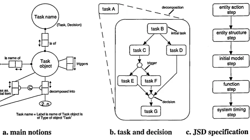
Jackson Structured Design (JSD) [Jackson 83] has grown out of JSP. It is a method for specifying and implementing computer systems with a strong time dimension. Again the functional specification describes the decomposition, detailing and refinement of processes. Apart from DSD and structure text, JSD uses an entity structure diagram (ESD) which employs the JSP notations to express the classical constructs of structured programming (figure 2.2). In addition, the system specification diagram (SSD) is used for arranging processes and data streams; and the system implementation diagram (SID) for process dismembering1. The major differences with the DeMarco SA is that JSD provides six clear steps for software development as follow:
• entity action step - define real world area of interest by entities and actions;
• entity structure step - arrange actions by each entity in their orderings with time (by ESD); • initial model step - describe connections with real world in terms of entities and action; • function step - specify functions to produce the outputs of the system (by SSD);
• system timing step - consider process scheduling which affect the system function outputs; • implementation step - consider software and hardware provided for running the system. Each step has detailed criteria. The important distinction in JSD is not between analysis and programming, but between specification (the first five steps) and implementation (the last step). JSD also stresses that structured design is an iterative process, though the aim is to minimise the number of cycles. Therefore, JSD is not a top-down design.
2.2.3 YOURDON MODERN STRUCTURED ANALYSIS (YOURDON)
Yourdon modern structured analysis (Yourdon) is another well-recognised method in software engineering. Aside from the traditionally structured tools, such as DFD, data dictionary and
process specification, Yourdon borrows the entity-relationship diagram (ERD) [Chen 76] to describe the stored data layout of a system at a high level of abstraction (figure 2.3a). In addition, the time-dependent behaviour of a system is described in a state transition diagram
(STD in figure 2.3b), which is a more effective way to describe event sequences in a complex entity than the entity structure diagram in JSD. Yourdon also handles real-time issues by introducing the control processes and control flows in DFD (figure 2.3c). One distinction of Yourdon is that it gives detailed techniques for balancing the models, that is for managing the various dependencies between different tools. For instance, each control process in DFD must be further specified in a STD. The control process in figure 2.3c is depicted as the STD in figure 2.3b where each state refers to the corresponding process in the DFD.
has, supertype
entity
subtyplm
X signal activate process B entity 1
Y signal activate process C
state C
I
subtype I entity 2 II
association! ^>bject_Jstate B state A
control (low X control proces
dataflow 1
control flowY proces proces
dataflow 2
data store
a. entity-relationship diagram b. state-transition diagram c. data flow diagram Figure 2.3 Yourdon Modern Structured Analysis Tools
Although Yourdon does not explicitly denote the analysis steps, the development process can be worked out from the four analysis models in the order presented below. For each model, Yourdon presents both the classical approach and its approach. In this way, the method description has a bigger contrast with the general practice.
2.2.4 STRUCTURED SYSTEMS ANALYSIS & DESIGN METHOD
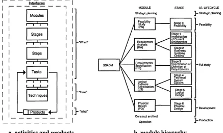
This method is normally abbreviated as SSADM [Downs 92], which is a method for developing computer-based information systems. It originated with the UK government’s Central Computer and Telecommunications Agency (CCTA), and is widely used in many development projects. The method consists of activities and products (figure 2.4a). The activities include ‘when’ and ‘how’ something should be done, whereas the products describe ‘what’ is delivered. The activity structure of SSADM is presented as a five module hierarchy (figure 2.4b). Each module, as shown below, is broken down into stages, steps and tasks. • feasibility study (FS) - includes non-SSADM work, such as financial cost/benefit analysis,
social evaluation or writing a feasibility report;
• requirement analysis (RA) - has two stages: it describes the investigation of current environment and establishes a range of business system options;
• requirement specification (RS) - reworks the descriptions of the current environment and business system option, produced in RA;
• logical system specification (LS) - has two stages: it determines and helps management to select the technical system options; and defines dialogues, updates and enquires in a non procedural logical design;
• physical design (PD) - takes the LS and combines it with information about the target hardware, software and organisation setting.
Interfaces
Modules
I—t*t—i
Stages i—r~i—i Steps i—r^ r Tasks i—r*T i i
i-Techniques -•H ow "
•f j Products
a. activities and products
Y
MODULE STAGE I.S. LIFECYCLE — Strategic planning Strategic planning
Stage 0
Feasibility - Feasibility
Stage 1 Investigation of Current Environment Stage 2 Business Systems Options Stage 3 Specification of Definition of Requirements Full study Stage 4 Technical System Options Stage 5 Logical Design Stage 6 Physical
Design - Development
Construct and lest
Production Operation SSADM Systems Specification
Ml
_____ Feasibility Study (FS) Physical Design (PD) Requirements Specification Requirement Analysis (RA) [image:39.615.57.495.435.696.2]b. module hierarchy
The individual stage and step descriptions can be found in [Downs 92]. However, it is interesting to note that SSADM defines each step in great detail by its input(s), output(s), tasks and techniques. The inputs and outputs provide the links to other steps, as well as giving the products associated with the step. SSADM comprises an extensive number of products for various tasks, such as DFD, logical data structure (LDS), entity life history
(ELH), effect correspondence diagram (ECD), business system option (BSO), technical system option (TSO) etc. This is illustrated by the feasibility study step 010 below:
Input(s)
• Project Initiation Document (from Project Procedures) Tasks
10. Working from any docum ents which initiated the study, create an outline description of the existing system and record known requirements
20. Establish the scope of the Feasibility Study, and agree with the Project Board
30. Tune SSADM to m eet the needs of the feasibility study and agree with the Project Board Techniques
• Data flow modelling • Logical data modelling • Requirem ents definition New or modified output(s) • Context Diagram (to 020)
• Current Physical Level-1 DFD (to 020) • Overview LDS (to 020)
• Requirem ents Catalogue (to 020)
• Agreed study method (to Project Procedures)
From the meta modelling viewpoint, these are significant pieces of information for describing the execution of products (concepts) in terms of tasks and techniques. The inputs and outputs are virtually the requirements and consequences of the step. Since SSADM is a structured method, the meta-structure of the method is also revealed in a top-down hierarchical form. That means it can only handle sequential processes so it does not promote iterative or parallel steps. This is considered as a drawback of the representation. As with other structured methods, SSADM does not stress data abstraction or information hiding. However, the latest version of SSADM (and JSD) has taken in some object-oriented (OO) features to solve this inadequacy and to accommodate the corresponding programming paradigm. SSADM is accompanied with automated tools such as LBMS SSADM and Automate-Plus, so it is not just a ‘paper-model’.
2.3 OBJECT-ORIENTED METHODS
a lot of software developers [Blair 91]. Object-oriented technology has entered the mainstream of industrial applications [Taylor 92] and research interests [Khoshafian 90]. In fact, ‘object-oriented’ has become an extremely overloaded term and very few commercial systems live up to the pure concept of object-orientation. Nevertheless, object-oriented methods have a major role in the technology. The main concern is not so much whether a method is object-oriented or not, but how it is object-oriented and in what way it delivers the associated benefits [Graham 91].
2.3.1 OBJECT-ORIENTED STRUCTURED DESIGN (OOSD)
Object-Oriented Structured Design (OOSD) is a method intermediate between analysis and design [Wasserman 90]. It is a notation for architectural design which combines structured methods with object-orientation, as promoted by [Ward 89] and [Champeaux 91]. OOSD is influenced by Yourdon’s structure charts, such as data flow, parameter passing and exception handling (figure 2.5a), but it also adopts object-oriented concepts such as encapsulation, instantiation and inheritance (figure 2.5b). In addition, concurrent or asynchronous processes are catered for by using monitors which are shown as parallelograms (figure 2.9c). These are important semantics for a requirements analysis as well as for a design method.
over t f <stack> t f under Item ^u l < stack> |.r£ item
under
class class
name name
instantiation f.
L b u ffe r/ buffering
inheritance
I generic
L class derivedclass
buffer
buffer data
a. exceptions in a stack object b. relationships
Figure 2.5 OOSD Notations
c. buffering monitor
2.3.2 OBJECT-ORIENTED SYSTEMS ANALYSIS (OOSA)2
Shlaer/Mellor’s OOSA [Shlaer 91] is a method for identifying the significant entities in a real- world problem domain and for understanding and explaining how they interact with one another. The entity modelling is descended from the Ward/Mellor real-time notation [Ward 85], hence OOSA users tend to be developer who migrated from the Ward/Mellor approach. The method is best described in three models, which OOSA refers to as three steps:
• information model - focus on abstracting the conceptual entities in the problem by objects, attributes and relationships - advanced entity-relationship diagram (figure 2.6a);
• state model - formalise lifecycles of objects and relationships from information model over time, in other words, express dynamic behaviour in state transition diagram (figure 2.6b); • process model - depict actions in state model as a fundamental and reusable process by an
enhanced form of the traditional DeMarco data flow diagram - action DFD (figure 2.6c).
is installed in powers
is powered by R2 \ I contains 1. OVEN [V]
* oven ID • status
3. LIGHT [L] * light ID • status 2. POWER TUBE [P]
• tube ID • wattage
• status___________
a. information model
LIGHT POWER TUBE
1. off
7K
L2: turn off [light ID] 1. de-energized /fT L1: P2: turn on de-energize [light ID] [tube ID]PI: energize [tube ID] V
2. on 2. energized
tube ID . L.1
light on tube ID L.2 light off P.2 turn off . tube . P.1 turn on . tube .
b. state model c. process model
Figure 2.6 OOSA Models for a One-Minute Microwave Oven
The early version of OOSA [Shlaer 88] cannot really be regarded as object-oriented due to the absence of inheritance. Entity subtyping is only introduced in a later book [Shlaer 91]. OOSA considers object identities by sets of attributes and keys (the status and IDs in figure 2.6a), then applies normalisation rules to the objects. Thus objects are regarded as relational tables rather than abstract data types.
From the meta modelling viewpoint, OOSA lays stress on strong cohesion between models. The labels and IDs provide the reference links amongst the models. For instance, in the
microwave oven example of figure 2.6, the tube ID in the information model is used in the data flows of the process model, whereas the actions PI and P2 in the state model refer to the processes P. 1 and P.2 in the process model. Furthermore OOSA is partially supported by the
teamwork CASE tool and commonly used in real-time applications, though the method does not have a rich description on either design steps or heuristic guidance.