Testing and Code Coverage of Fiber Channel Based
Transceiver for Avionic Applications
Anurag IM1, Dr Ananda CM2, Mrs. Hamsaveni N3
1P.G Student, Dept. of Electronics and Communication Engineering, SJB Institute of Technology, Kengeri, Bengaluru, India
2Head, Aerospace Electronics and Space Division CSIR National Aerospace Laboratories, Bangalore, India
3Associate Professor, Dept. of Electronics and Communication Engineering, SJB Institute of Technology, Kengeri, Bengaluru, India
Abstract: In present era of communication there is an urge for high speed data access along with high quality multimedia
transmission of audio, video and data which has seen a drastic increment in computer network bandwidth capacities at a faster rate. Increase in performance utilization of bandwidth is demanding for discrete consequences and thereby stressing the importance in areas of interconnect and the area of performance. Because of all these reason, it can be seen that there is an exponential increase in aircraft and avionic environments in case of the technological requirements of networks. In this paper we test the crucial test scenarios for the major modules of the transceiver designed. It can be seen that transceiver that has been designed for faster communication is being tested for its reliability and efficient handling of the errors using Xilinx ISE and code coverage for the proposed system is determined by the QuestaSIM tool.
Keywords: Fiber channel, Avionic, Testing, Reliability, Critical conditions, Xilinx-ISE Testbench, QuestaSIM, Code coverage.
I. INTRODUCTION
In general, testing is done to provide the information related to the product about its quality or the service by the product which is kept under test for the stakeholders. The testing also provides the objective of viewing the design to understand the risks and cons of the design implemented. The technique which includes the process of execution of a design in an expectation of bugs is called as errors and defects. Testing and verification is mainly carried out in order to ensure the product or the design implemented is worth for use.
In general, these properties figure out the duration to which the component or the design module that is under the test: Accomplishes the set of requirements that are pre-defined.
Meeting the expected outputs for all kinds of the inputs. Meeting the deadlines of the functions under execution. Effective usability
Meeting designed flexibly so that it can work satisfactorily in proposed environment.
We can observe that there are infinite possible tests for every simple module that is being designed. Hence we use some statistics in order to select some tests that are expedient for the available time and resource. The testing is mainly done or attempted to execute a design, application or a set of codes with a connotation to detect the flaws and breakdowns in the code. This testing is a repetitive process as when one bug is settled, it can give rise to another, rooted errors or even it can set up a new one.
The testing can also provide the main purpose, self-reliant information on the nature of implemented code and liability of its breakdown to the user. Conduction of the testing for executable design or code can be done even if it is partly finished. The comprehensive proposal for the development demonstrates when and how the testing is exhibited.
The outlook of testing is the inclusive of examination and execution of the code or design in discrete environments as well as conditions that investigate the facets of the code. The assessment of the developed code is observed, whether the developed code is meeting the requirements of the end users, its defined congregation and its patron.
A. Fiber Channel Communication
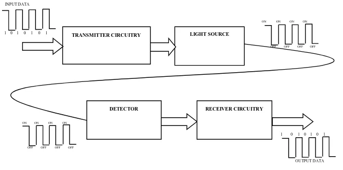
considered as fabric optic communication as an ideal for gigabits and far off above gigabits transmission of data. A method for transmission of information between two places is done through sending of information through pulse in the form of light in optical fibers is termed as FC Communication. This type of communication is very well used in the transmission of telemetry signals, audio and video signals and data for the far away distances and local area or computer networks. The light is used as the medium of transmission of information using optical communication technology by transmission over farther distances using fiber cables. However in the recent past, aerospace industry started using the fiber channel based communication for higher bandwidth applications in avionics and hence the need for such communication protocol IPs. The basic steps invoked in the fiber optic communication are as follows:
1) Transmitter is used for transmission of optical signals. Hence the usual signals are electrical signals that are converted to optical.
2) Ensure that the signal doesn’t get distorted or weakened, boosting up of signal is done.
3) Reception of the transmitted optical signal.
[image:3.612.143.477.265.431.2]4) Received optical signal is converted into electrical signal.
Fig 1: Basic communication diagram
II. DESIGN
A. Basic layered structure of FC Protocol
This section gives the structure, concept and mechanism of the frame design. Fiber Channel (FC) has a high performance facility because of its logical bi-directionality, point-to-point and serial data channel. Few of the combinations of topologies are given below in which Fiber Channel may be implemented:
1) Two ports connected via point-to-point;
2) Switching network called as fabric is interconnected to number of ports; and
3) A loop network being interconnected with the set of ports.
It also provides generalized transport layer for Upper Level Protocols (ULPs) like SCSI command sets and Protocols like IP. This describes the related functions FC-1, FC-2, and FC-3. It is treated as a layer for each of these functions as shown in fig 2. There are no restricted implementations of few interfaces between levels [1]. A variety of physical media, associated drivers and receivers capable of operating at various speeds are specified to address variations in cable plants [1][2][3].
The three different hierarchical layers FC-1, FC-2 and FC-3 are all almost interspersed. Fiber Channel Link services explain about Extended Link services. The Fiber Channel protocol affords a wide spectrum for all the potentiality towards reduced cost to higher performance.
The medium of transmission is isolated from the control protocol in such a way that each implemented module uses the best suited technology as per the environment in which it is being used. One or more ports of FC-4 can be supported by the node. Each node port contains FC-0, FC-1 and FC-2 functions. FC-3 intentionally provides the familiar services to multiple node ports and FC-4s [1][2].
OFF OFF OFF OFF ON ON ON ON
ON ON ON ON
OFF OFF OFF OFF
DETECTOR RECEIVER CIRCUITRY
OUTPUT DATA 1 0 1 0 1 0 1
LIGHT SOURCE TRANSMITTER CIRCUITRY
INPUT DATA
Fig 2: Layered diagram of FCAE.
B. Block diagram of Transceiver
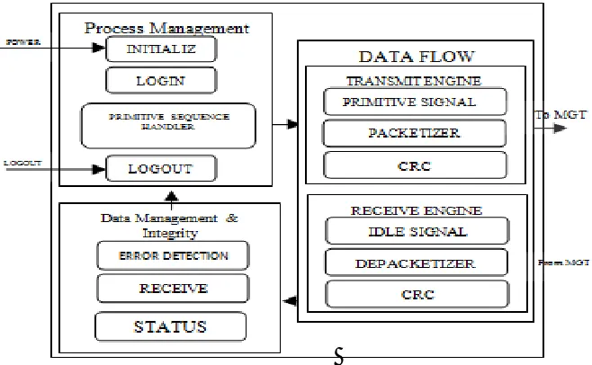
[image:4.612.126.455.373.576.2]Transceiver mainly contains three blocks. They are Process management, Data Flow block and Data Management and Integrity block.
Fig 1.2: Basic block diagram of TRANSCEIVER
C. The Process Management Block
Link is established as well as managed in this module. The block includes the initialization of link and sharing of resources available. Link initialization is initiated when the device is ON and observed when the system moves from offline state to online. Login is a process in which exchange of services and class related specification is performed. For every Login there is a corresponding logout process. There are three types of login and each one has its own functionality. Login is done after link is initialized. There are chances of failure and resets that may occur in the system. When failures and reset occurs a certain set of sequences are being executed from initial state [1][2].
Resource availability is known during the login procedure and is utilized for the purpose of communication. The logout process aborts the login and there will be no transmission of data until the ports are logged in again [3].
F C -0 P h y si ca l
FC-1 Transmission protocol FC-2 Signaling protocol
FC-3 Linking protocol ULP FC-4 Mapping T h is s ta n d a rd . P C -P I-X
TRANSMITTER AND RECEIVER
SCSI IPV4,
IPV6
SBCCS OTHERS
VIA TRANSMISSION PROTOCAL SIGNALLING PROTOCAL MEDIA EXTENDED LINK SERVICES
FC-VI FCP-3 RFC
4338 FC-SB-3 OTHERS
III.DATAFLOWBLOCK
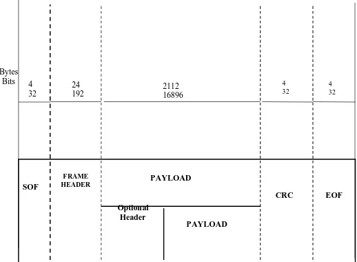
The major role played by data flow module is packetization at the transmitter and depacketization of the frame at the receiver end. A block of bytes brought together with has a control information is defined as a Frame. This block consists of the Transmit and the Receive engine. The transmit engine is further divided into three sub-modules. They are the Primitive Signal Generator; Packetizer and the CRC (Cyclic Redundancy Check) generator. All these three sub-modules have their own functionalities. The Primitive Signal generator generates the primitive signals that are required for managing the linking operations. Packetizer is utilized for the generation of frames. These frames together form a sequence. The CRC generator generates the redundancy word, which are used to verify the integration of the data of extended header and the frames. When there is buffer space available for the accommodation of the frames, a Ready signal is generated by the Primitive Signal Generator upon the request of the receiver. There is a standard frame structure for packetization. Start Of Frame (SOF), Frame header, Data field, CRC and End Of Frame (EOF)are the five major fields [1]. The sequence is generated based on the standard format and transmitted accordingly. The SOF that presides the frame contents is the ordered set. The EOF immediately follows the CRC. Depending on the payload, the frame header values are decided.
The basic formula for the calculation of CRC is the remainder of modulo-2 division for the original transmitted bits. The generalized standard polynomial equation for the CRC Calculation is given by
G(x) = x32 + x26 + x23 + x16 +x12 + x11 + x10 + x9 +x7 +x5 + x4 +x2 + x +1[2][3].
At the receive engine the transmitted frames are received through receive buffer and checks for the presence of idle frames. The received idle signals are discarded and rest of the frame is depacketized. The received application data frame and the Extended Link Service (ELS) command frames are separated based on the header received and sent for further processing. The transmitted frames are received at the receive engine through the receive buffer and checked for the presence of idle primitive signal. The received CRC is compared to the calculated CRC and the frame is discarded if there is any difference between transmitted and received the CRC.
IV.DATAMANAGEMENTANDINTEGRITYBLOCK
The integrity of the link services and the status of the transmitter and receiver are maintained in this block. The receiver decision block decides if the received word is a primitive sequence or a part of the frame and sends it to the required module. All the operations carried out are updated in status block. Flow control decides if the packet or frames can be transmitted after ascertaining the buffer space available. Error detection and correction is also carried out in this block [2].
V. FCAEFRAME
[image:5.612.180.439.502.692.2]“Packet” is referred as a block of information or data that has to be transferred. Extra information is required for the control of packets when placed in physical bus. The data is transmitted in a succession of one or more frames. A data of large size is segmented into a number of frames at the transmitter. Basic structure of the frame is shown if fig 4 [1]:
Fig 4: Structure diagram of a standard frame.
SOF PAYLOAD FRAME HEADER Optional Header PAYLOAD
CRC EOF
Bytes Bits 4
VI.TESTINGANDVERIFICATION The fig 5 shows the basic block diagram that has been considered for testing
Fig 5: Block diagram of Transceiver
Based on the design every module is tested for various test scenarios. In transmission block, Primitive Sequence Handler, Header and FCAE generator are considered as the major blocks for testing. At the receiver end, Receive engine, CRC and Receiver Decision Block are the major blocks for testing and verification. Primitive Sequence Handler is responsible for the implementation of primitive sequence protocol. In Primitive Sequences, Link initialization helps in establishing a communication path between two systems. Whenever there is failure or interruption caused during the establishment of path or channel, the Primitive Sequence generates primitive sequence protocols such as link failure and link reset.
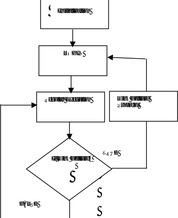
A. Initialization
After Power ON, the system tries to establish link with the other system by transmitting the offline primitive sequence and initiating the Link Initialization protocol. The necessary states for initialization are carried out as shown in fig 6.
B. Primitive Sequence Handler
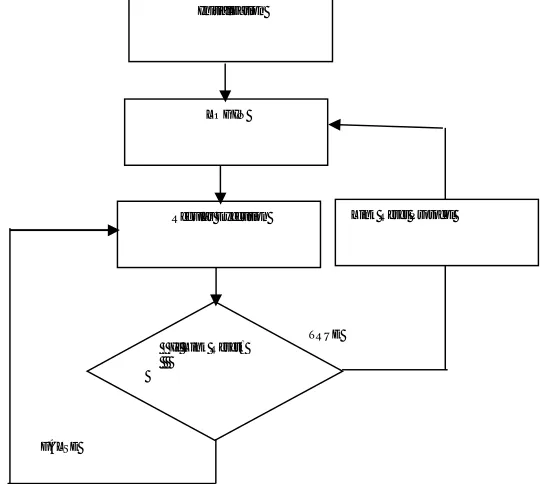
Fig 7 shows the flow diagram of link failure. After the initialization and login process, link failure condition is continuously monitored. The failure condition occurs due to the loss in synchronization and loss of signal.
Fig 7: Flow diagram of Link Failure
Transmitter
Receiver
Header Primitive Sequence
Handler
FCAE
Receive Engine
CRC
Receiver Decision Block
TRUE
If Link Failure? LOGIN
Regular Execution Link Failure Protocol Initialization
[image:6.612.206.390.470.695.2]The test scenario is created for failure case and checked for the initiation of link failure protocol.
Fig 8: Flow diagram of Link Reset
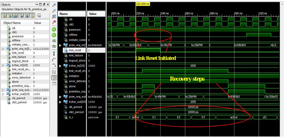
Fig 8 shows the flow diagram of link reset. After the completion of initialization and the login process, the link reset condition is continuously monitored. The link reset is initiated because of Link Timeout and when there is buffer to buffer overflow. A test scenario is created by initiating the reset condition manually and the necessary recovery protocol initiated is observed in the Fig 8a.
C. Transmitter
Transmit engine has Header Generator and the FCAE Frame Generator. Header Generator generates the 24 byte header for the frame. The header gives the information about the type of frame being transmitted. The Header Generator is tested by checking the contents of the header in each cycle for different types of frames. FCAE Frame Generator generates the frame as per the design.
D. Receiver
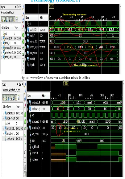
Receive engine identifies the different payloads received from the transmitter. Receiver Decision block is tested with the various test scenarios by transmitting different primitive sequence and data frames to the module as shown in fig 10.
CRC is the module which is present at both transmitter and receiver. The calculated CRC is added to the frame and transmitted. The frame is received by the receiver and the integrity is checked with the CRC calculated at the receiver end. Fig 11shows the CRC Value generated.
The entire process of testing and verification for the design is carried out using the ISE tool. QuestaSIM is a tool which is used for determining the code coverage. This tool helps in understanding the code coverage, functional coverage of the entire design. Using Questa tool each branch and its condition are tested for all the possibilities in the design. Both the cases, true and false for each condition is executed and tested. The code is optimized so that the complexity of the code and the memory usage is reduced which in turn reduces the power consumption. The tool QuestaSIM also covers the function, statement, branch, expression, toggles and FSM in a design. The code is checked for the proper execution and desired functionality. Every state is tested and verified with the number of true as well as false hit of the cases by running the code for larger period of time. The state machine is also available in order to check for the transmission of flow of control from one state to the other. The design under test is tested and verified using the manual direct forcing of test benches. This QuestaSIM also helps in running a code for a desired period of time by optimizing the code which helps in detecting the errors in the code that can be observed only after running the code for larger periods [3].
FALSE
TRUE
Initialization
If Link Reset?
LOGIN
VII. RESULTS
A. Initialization
[image:8.612.66.571.115.400.2]The test scenario checks the correct transmission and reception of the primitive sequence as shown in fig 6.
Fig 6: Waveform of Power ON in Xilinx ISE
B. Primitive Sequence Handler
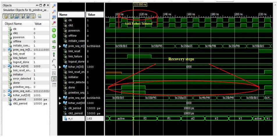
Fig 7a shows the necessary recovery steps initiated during the case of Link Failure. Fig 8a shows the necessary recovery steps initiated during the case of Link Reset.
Fig 7a: Waveform of Link failure in Xilinx ISE.
Recovery steps
Power On
Link Failure Initiated
[image:8.612.52.530.464.701.2]Fig 8a: Waveform of Link Reset in Xilinx ISE
[image:9.612.50.532.352.642.2]C. Transmitter
Fig 9 shows the Frame generated according to the design standards.
Fig 9: Waveform of FCAE Frame Generator in Xilinx
D. Receive
The transmitter is tested for the proper generation of frame with SOF followed by the Frame header, Data payload, CRC and EOF and the receive engine is tested for the proper depacketization of different types of frame as shown in fig 10. Fig 11 shows the CRC calculation and comparison with the CRC reset and valid signals.
Link Reset Initiated
Recovery steps
Fig 10: Waveform of Receiver Decision Block in Xilinx
Fig 11: Waveform of CRC Check for valid and reset in Xilinx.
The designed code is tested and verified with the maximum code coverage.
Below fig12 is the waveform of the Link Initialization and Primitive Sequence Handler process that is observed and verified in QuestaSIM tool, for which link failure and link reset has been manually forced with Power ON and OFF conditions and the required
Transmitting sequence
Receiving sequence
Fig 12: Waveform of Link failure and reset in QuestaSIM Fig 13: Waveform of CRC calculation & generation in QuestaSIM
The fig 13 is the waveform of the CRC calculation and its change of states which is tested and verified using the QuestaSIM tool. It is observed that the CRC generator is generating CRC with the expected outputs and coverage is determined.
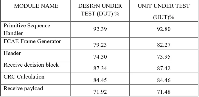
The Code and Functional coverage also plays a prominent role for the design check, verification and optimization process. Crucial modules are individually tested and the Code Coverage percentage is determined.
The below shown tab 1 is the Code coverage that is being generated by the QuestaSIM for various modules of the design [5].
MODULE NAME DESIGN UNDER
TEST (DUT) %
UNIT UNDER TEST
(UUT)% Primitive Sequence
Handler 92.39 92.80
FCAE Frame Generator
79.23 82.27
Header
74.30 73.95
Receive decision block
87.34 87.42
CRC Calculation
84.45 84.46
Receive payload
71.92 71.48
Table 1: Code coverage for the design modules[5].
VIII. FUTUREENHANCEMENTS
On future enhancements the test scenarios has to be upgraded such that the design can be tested in a very optimal method. The reusability of test scenarios has to be designed in order to reduce the resources for execution as well as the effort for generating the test scenarios. The test design has to be tested for the different upper layer protocol. For the transmission of an image or any other format of data, the test scenarios have to be upgraded and the code has to be rebuilt.
IX.CONCLUSION
A networking technology using Fiber Channel as a medium is designed for high speed data transfers. This design has been tested and verified for the entire possible test scenarios and has been successful for the higher speed of communication. Fiber Channel is now being used widely in telecom, storage and aircraft applications with a minimal possibility of failures. This design with initial test cases for data transfer and reception of data has led to satisfactory results.
X. ACKNOWLEDGMENT
Authors would like to thank Mr. Jitendra J Jadhav, Director, NAL for continuous support and motivation. Authors would also like to
Link Reset Power On
[image:11.612.133.467.344.507.2]express their sincere gratitude to Mr.Pradeep Kumar B, Mr. Ramanathan S G and team for their support. Authors would also like to thank SJB Institute Of Technology and Department Of Electronics and Communication for their continuous support and encouragement.
REFERENCES
[1] ISO/IEC 14165-251, Fiber Channel - Framing and Signaling (FC-FS) [ANSI INCITS 373-2003].
[2] MachavaramVenkata Dinesh, CM Ananda, Pradeep Kumar B, Jay Kumar E.P. “Design and Implementation of fiber Channel Based High Speed Receiver Protocol for Avionics on FPGA”, 2016 IEEE International Conference on Recent Trends in Electronics, Information & Communication Technology (RTEICT), 2016.
[3] PadmavathiNarapureddy, C M Ananda, B Pradeep Kumar, E P Jaya Kumar. "Design and implementation of fiber channel based high speed serial transmitter for data protocol on FPGA", 2016 IEEE International Conference on Recent Trends in Electronics, Information & Communication Technology (RTEICT), 2016.