Technology (IJRASET)
Experimental Behavior of Full Encased Composite
Column under Axial Compression
Sagar Patil1, Dr. Suresh Parekar2
1
M.E. Structures, AISSMS COE, Pune University
2
H.O.D. Associate Professor, Dept. of Civil Engineering, AISSMSCOE, Pune University
Abstract: This paper presents the experimental behaviour of full encased composite columns (FECC) under axial compression. A composite column is a column in which steel section is embedded into concrete with longitudinal reinforcement as well as lateral reinforcement. In this papers results of full encased composite columns were compared with the conventional reinforced concrete columns and are presented in the form of graphs and tables. From the experimental results it was concluded that FECC can replace conventional reinforced concrete column when subjected to high compressive loads. Failure mode of both FECC and conventional reinforced concrete column were almost same.
Keywords: Full encased composite column, conventional reinforced concrete column, Longitudinal reinforcement, Compressive loads and axial compression.
I. INTRODUCTION
A composite column is a compression member which may either be made up of a structural steel sections encased by concrete or concrete filled in hollow circular/rectangular steel tube. The use of steel-concrete composite columns, such as concrete encased steel (CES) and concrete-filled steel tube (CFT) columns, has increased in the construction of high-rise buildings and long span structures. In particular, the use of high strength materials in composite columns is growing to improve structural safety, economy and to reduce the column size.
It has got a few advantages over the conventional reinforced concrete construction: (1) due to its higher strength and stiffness, cross-sectional area reduces; (2) reduces material consumption and project execution time; (3) inherent ductility resulting in suitability for earthquake loading; and (4) provides good fire resistance.
As a result, it is becoming increasingly popular in the construction industry particularly in foreign countries, those having a definite design guideline based on their individual codes of practice and advanced construction techniques/equipments. In the present study the main objective is to study the behavior of full encased composite column and to prove it is a better alternative to reinforced concrete column when subjected to high compressive loading.
II. FABRICATION OF SPECIMENS
In the present experimental study total 18 specimens of height 600 mm were cast with slenderness ration less than 12. Out of 18 specimens, 6 specimens have circular FECC sections with circular and rectangular encasement i.e. 3 with circular encasement and 3 with rectangular encasement, 6 specimens have rectangular FECC sections with circular and rectangular encasement i.e. 3 with circular encasement and 3 with rectangular encasement and remaining 6 columns were cast using conventional reinforced concrete as a control specimen with varying cross section i.e. rectangular and circular.
The steel pipe section was of 1.6 mm thickness. The size of control specimens considered for circular section is on the bases of least lateral dimension required for reinforced concrete column as specified in IS 456:2000.
Sr. No. Specimen Designation
Dimension (mm)
Ag (mm2)
1 CCC
230 41547.56 2 CCCE
3 CCRE 4 CRC
230 x 180 41400 5 RCCE
6 RCRE
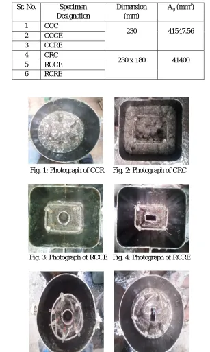
Fig. 1: Photograph of CCR Fig. 2: Photograph of CRC
Fig. 3: Photograph of RCCE Fig. 4: Photograph of RCRE
Fig. 5: Photograph of CCCE Fig. 6: Photograph of CCRE
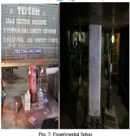
III. EXPERIMENTAL SETUP AND TESTING
[image:3.612.148.455.86.599.2]Technology (IJRASET)
Fig. 7: Experimental Setup
IV. EXPERIMENTAL RESULTS
All the specimens were tested at a uniform rate of loading up to failure and deformation was recorded at regular interval of loads. The mode of failure was observed for all specimens. Test results for all the specimens are presented in Table 1. From the test results it was observed that the encasement of steel pipes in concrete proves to be more effective in load carrying capacity. The failure modes of the tested columns with and without the encased steel section were almost the same. Ultimate deformations recorded at ultimate load of FECC were not much more than the control specimens.
TABLE 2: EXPERIMENTAL RESULTS
V. MODES OF FAILURE
The failure modes of the concrete columns with and without the encased steel section were almost the same. Ultimate deformations of both FECC and recorded at ultimate load of FECC were not much more than the control specimens. The failure of control specimens and failure of FECC specimens was due to vertical cracks occurred at the column surface and with increasing of the applied load cracks become wider and the cover started to spall off.
Sr. No.
Column Designation
Ultimate Load (kN)
Ultimate Deformation
(mm)
Remark
1 CCC 931.70 6.01 Concrete spall off at top and then crushing
2 CCCE 1064.80 6.43 Spalling of concrete and bulging at top
3 CCRE 1137.40 6.83 Spalling of concrete and bulging at top
4 CRC 1089.00 6.42 Concrete spalling and then crushing
5 RCCE 1282.60 6.54 Spalling of concrete and then crushing
Fig. 9: Failure of Control Specimen and FECC
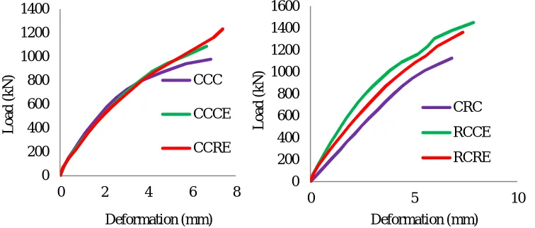
Fig. 10: Load vs deformation graph of control and composite columns
VI. CONCLUSIONS
From the experimental results it was observed that percentage increase in ultimate load carrying capacity of rectangular composite column by 17.78 % than the control rectangular column and rectangular composite column by 18.89 % than the control rectangular column.
From the experimental results it can be concluded that FECC can replace conventional reinforced concrete column when subjected to high compressive loads.
From load vs deformation behavior it can be concluded that the composite column provides more resistance to deformation at higher compressive load than the conventional reinforced concrete column due to encasement.
REFERENCES
[1] Caihua Chen, Cuikun Wang, and Huizhong Sun, “Experimental study on seismic behavior of full encased steel-concrete composite columns, ” Journal of Structural Engineering, pp 44-56. 2014.
[2] Chang-Soo Kim, Hong-Gun Park, Kyong-Soo Chung and In-Rak Choi , “Eccentric axial load capacity of high-strength steel-concrete composite columns of various sectional shapes, ” Journal of Structural Engineering, pp 55-67. 2013.
[3] Cristina Campian, Zsolt Nagy and Maria Pop, “Behavior of fully encased steel-concrete composite columns subjected to monotonic and cyclic loading, ” Journal of Procedia engineering, pp 439-451. 1997.\
[4] Ehab Ellobody and Ben Young, “Investigation of concrete encased steel composite columns at elevated temperatures,” Journal of Thin walled structures, pp 597-608. 2010.
[5] Zhang-Fei Huang, Kang-Hai Tan and Guan-Hwee , “Axial restraint effects on the fire of composite columns encasing I-section steel, ”Journal of constructional steel research, pp 437-447. 2008.
0 200 400 600 800 1000 1200 1400
0 2 4 6 8
L o a d (kN ) Deformation (mm) CCC CCCE CCRE 0 200 400 600 800 1000 1200 1400 1600
0 5 10