Page 107
Under-Water Welding Using Robotic
Technology
V.Prasanth1, S.Sukesh Kumar2, Dr.R.Gnanaguru3
1,2
Final year Mechanical 3
Professor & Head / Mechanical, Narasu’s Sarathy Institute of Technology,Salem
.
Abstract: Welding in offshore and marine application is an area of research and understanding, where many problems are still unsolved. The important application of the off shore welding is the ship building and pipeline construction. Since underwater welding is done at the elevated pressure, the care must be ensured to improve the welder’s safety. Hence the robotic technology is recommended to overcome the problem relating to the life threat of the welder’s. In this paper, a brief description of the robot, designed for the underwater welding is made. The problems in underwater welding have also been discussed in context to the existing welding techniques. Finally, the scope of further research has been recommended.
Keywords: Underwater Welding, Welder’s Safety, Robotic Technology.
I. INTRODUCTION
The recent developments in the manufacturing world have led to a revolutionary change in the design and development of various systems. Developments in welding technology are one of such changes. Welding processes have been used extensively as a joining technique, used in design and fabrication of various structures like naval ships, airplanes, automobiles, bridges, pressure vessels, etc. Welding has emerged as a better option in contrast to other joining techniques in terms of joint efficiency, mechanical properties with a greater application impact.
In some intricate situations, the Robot based welding processes have replaced human welders. During the last few years, the automation of welding process for pipe structures have gained significant momentum with an objective to improve the productivity and accuracy in the areas involving marine applications, etc. Various research studies in the welding environment have shown that productivity improvement is a major thrust area of welding industry. The welders in today’s world are under tremendous pressure to meet two major challenges. These are: the higher weld quality and; reduced manufacturing cost.
Another emerging area in marine application welding systems is the underwater welding technique. Underwater Welding (UW) has been significantly used for over five decades. However, its use has not reached to a significant level in a welding environment due to number of factors. The underwater welding process came into existence with the development of water-proof electrodes in 1940’s (Keats, 2005). It is the process of welding at elevated pressures, normally underwater. It may be carried out in the water itself or dry inside a specially constructed positive pressure envelope, thereby providing a special environment. Under water is also known as “hyperbaric welding” when used in a dry environment, and “underwater welding” when in a wet environment. The application areas of this welding technique include a wide variety of structures, such as repair ships, offshore oil platforms, and pipelines. Steel is the most common material welded (Cary and Helzer, 2005). Various researchers have defined the concept of underwater welding in different ways (Haddad and Farmer, 1985; Oates, 1996; Schmidt, 1996; Khanna, 2004; and Cary and Helzer, 2005).
II. IMPORTANCE OF UNDERWATER WELDING IN MARINE APPLICATIONS
Page 108
techniques. Detailed description of a few advanced welding techniques has also been made. Finally, the scope of further research would be recommended.
III. CLASSIFICATION OF UNDERWATER WELDING
Underwater welding may be divided into two main types, wet and dry welding (Oates, 1996).There are many welding types in each case. Wet type is considered here in this robotic welding.
IV. WET WELDING
This type of welding process is carried out at ambient water pressure in which, there exists a relationship between the welder and the diver in the water. This is carried out by means of a water-proof stick electrode, with no physical barrier between water and welding arc (Oates, 1996).
In wet welding technique, the complex structures may also be welded (Oates, 1996; Shida et al., 1997; Khanna, 2004; and Kruusing, 2004). One of the most commonly used wet welding techniques is the Shielded Metal Arc Welding (SMAW) process and the Flux Cored Arc Welding (FCAW) process. It also includes the self-shielded flux cored arc welding. From economics point of view, the wet welding technique with coated electrodes is considered. The cooling rate in wet welds is much higher than in those obtained in dry welding. In the temperature range from 800 to 500 °C it can change from 415 to
56 °C/s (Steen, 1991). Underwater wet welds are also known to contain high amounts of porosity. Porosity may be formed by molecular hydrogen, carbon monoxide or water vapour (Irie et al., 1997; Cavaliere et al., 2006; and Cavaliere et al., 2008). Pores are present to some extent in all wet welds. The main factors affecting this phenomenon are (Shida et al., 1997; Irie et al., 1997; Cavaliere et al.,2006; and Cavaliere et al., 2008): water depth, electrode covering and arc stability.
Special precaution should be taken to produce underwater arc to protect it from surrounding water. Wet welding does not need any complicated experiment set up, it’s economical and can be immediately applied in case of emergency and accident as it does not need water to be evacuated. However, difficulties in welding operation due to lack of visibility in water, presence of sea current, ground swells in shallow water and inferior weld qualities (increased porosities, reduced ductility, greater hardness in the heat affected zone, hydrogen pick up from the environment) are the notable disadvantages of wet welding technique.
V. SHIELDED METAL ARC WELDING
Page 109
Fig1: Schematic of shielded metal arc welding
VI. ROBOTICS
Robot is a machine capable of carrying out a complex series of actions automatically, especially one programmable by a computer. The word robot was introduced to the public by the Czech interwar writer Karel Čapek in his play R.U.R. (Rossum's Universal Robots), published in 1920.(Zunt, Dominik, 2007) The play begins in a factory that uses a chemical substitute for protoplasm to manufacture living, simplified people called robots.
VII. PARTS OF UNDERWATER ROBOTIC WELDING
The robot that is designed for the underwater welding is based on the submarine design. The main parts of the robot is
Propeller
Electromagnetic Wheels Welding Rod holder and Rod Stepper Motors
ATmega 16 Microcontroller Camera
Lights a.) Propeller
A propeller is a mechanical device for propelling a boat or aircraft, consisting of a revolving shaft with two or more broad, angled blades attached to it. There are 4 propellers used in this robot. Two propellers face the front side and the other two propellers face the top side. When the propellers in the front rotate clockwise the robot moves forward and vice versa for anticlockwise direction, and when the propellers at the top rotate clockwise the robot moves up and vice versa for the anticlockwise direction. The side wards movement i.e. Right to left is done by deflecting the propeller arm.
Fig2: NX CAD model of propeller b.) Electromagnetic Wheels
Page 110
Fig 3: NX CAD model of electromagnetic wheels c.) Welding Rod Holder and Rod
The positive side of the DC power supply is given to the welding rod holder and whereas the metal to be welded is given with the negative charge. The rod used here is the consumable rod and the rod is flux coated with the insulated material suitable for the underwater welding.
Stepper Motor
A stepper motor (or step motor) is a brushless DC electric motor that divides a full rotation into a number of equal steps. The motor's position can then be commanded to move and hold at one of these steps without any feedback sensor (an open-loop controller), as long as the motor is carefully sized to the application. The stepper motor is connected to the H-Bridge and is interfaced to the microcontroller.
There are four main types of stepper motors: (Liptak, Bela G., 2005) Permanent magnet stepper
Hybrid synchronous stepper Variable reluctance stepper Lavet type stepping motor
Permanent magnet motors use a permanent magnet (PM) in the rotor and operate on the attraction or repulsion between the rotor PM and the stator electromagnets. Variable reluctance (VR) motors have a plain iron rotor and operate based on the principle that minimum reluctance occurs with minimum gap, hence the rotor points are attracted toward the stator magnet poles. Hybrid stepper motors are named because they use a combination of PM and VR techniques to achieve maximum power in a small package size.
Fig 4: Stepper Motor e.) ATmega 16 Microcontroller
[image:5.612.266.392.522.604.2]Page 111
[image:6.612.197.414.152.264.2]Microcontrollers are used in automatically controlled products and devices, such as automobile engine control systems, implantable medical devices, remote controls, office machines, appliances, power tools, toys and other embedded systems. By reducing the size and cost compared to a design that uses a separate microprocessor, memory, and input/output devices, microcontrollers make it economical to digitally control even more devices and processes.
Fig 5: ATMEGA 16 Microcontroller
Camera
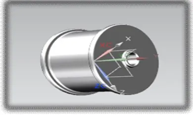
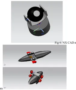
[image:6.612.57.310.399.700.2]Camera is a device for recording visual images in the form of photographs, film, or video signals. The camera here converts the image to the co-ordinate system. This co-ordinate system helps to find the weld area in this context. The camera here is supported by the focus light system on the either side.
Fig 6: NX CAD model of camera
Lights
Page 112 during the weld. This exclusive model of a robot will be a solution for the
problems related to the underwater welding. There is Light is the natural agent that stimulates sight and makes things visible. The light here supports the camera to generate the better picture.
VIII. OPERATION OF THE UNDER-WATER ROBOT WELD
The operation of the robot is controlled by the micro controller. The microcontroller gets its input from the computer system. The wired interface is used because it’s unable to construct an wireless design efficiently in the place having the elevated pressure. The electromagnetic wheels and propellers are actuated by the stepper motors. This stepper motors are interfaced to the microcontroller using the H bridges. The movement of the robot is done using the propellers and electromagnetic wheels are used to stick to the surface. The camera helps to find the area of the weld and converts it into the coordinate system. This co-ordinate system helps to monitor the weld and make a weld accurately on the surface. The figure below is the NX CAD model of the robot also a numerous future scope for this system.
REFERENCES
[1] Anand and Khajuria(2013), welding processes in marine applications: a review, International Journal of mechanical engineering research and robotics, Vol.2, Jan2013, ISSN 2278-0149
[2] Cary H B and Helzer S C (2005), Modern Welding Technology, Upper Saddle River, Pearson Education, New Jersey.
[3] Cavaliere P, Campanile G, Panella F and Squillace A (2006), “Effect of Welding Parameters on Mechanical and Microstructural Properties of AA6056 Joints Produced by Friction Stir Welding”, J. Mater. Process. Technol., Vol. 180, pp. 263-270.
[4] Cavaliere P, Squillace A and Panella F (2008), “Effect of Welding Parameters on Mechanical and Microstructural Properties of AA6082 Joints Produced by Friction Stir Welding”, J. Mater. Process. Technol., Vol. 200, pp. 364-372.
[5] Haddad G N and Farmer A J (1985), Weld. J., Vol. 64, No. 12, pp. 339-342. [6] Irie T, Ono Y, Matsushita H et al. (1997), Proceedings of
16th OMAE, pp. 43-50.
[7] Keats D J (2005), Underwater Wet Welding—A Welder’s Mate, Speciality Welds Ltd. [8] Khanna O P (2004), A Textbook of Welding Technology, Dhanpat
Rai Publications (P) Ltd., New Delhi, India.
[9] Kruusing A (2004), Optics and Lasers in Engineering, Vol. 41, pp. 329-352. [10] Liptak, Bela G. (2005). Instrument Engineers' Handbook: Process Control and Optimization. CRC Press. p. 2464. ISBN 978-0-8493 1081-2.
[11] Oates W A (Ed.) (1996), Welding Handbook, Vol. 3, American Welding Society, Miami, USA.
[12] Schmidt H-P (1996), IEEE Transactions on Plasma Science, Vol. 24, pp. 1229-1238. [13] Shida T, Hirokawa M and Sato S (1997), Welding Research
Abroad, Vol. 43, No. 5, p. 36.
[14] Steen W M (Ed.) (1991), Laser Material Processing, Springer Verlag, New York. [15] Zunt, Dominik. "Who did actually invent the word "robot" and