Technology (IJRASET)
Multiband E-Shape Microstrip Patch Antenna
Shobhit Kumar Mishra1, Dr. B.S.Rai2
1,2
Electronics and Communication Engineering
Madan Mohan Malaviya University of Technology, Gorakhpur (Uttar Pradesh) Pin -273010
Abstract:A new broad-band design of a microstrip line feed rectangular patch antenna with a pair of wide slits are proposed and experimentally studied. The proposed design with an FR4_epoxy substrate, and experimental results show that, simply by inserting a pair of wide slits at one of the radiating edges of the rectangular patch, good impedance matching over a wide bandwidth can easily be achieved for the proposed antenna. With an FR4_epoxy substrate of thickness about 8% of the wavelength of the center operating frequency, the proposed antenna can have an impedance bandwidth of about 33.33%. For frequencies within the impedance bandwidth, good radiation characteristics are also observed, with a peak antenna gain of about 7.2 dBi.
Keywords- Patch Antenna, Bandwidth, Return loss
I. INTRODUCTION
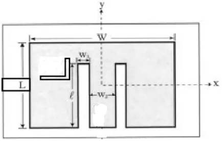
[image:2.612.198.415.420.558.2]It has been known that, For bandwidth enhancement various techniques are used such slot cutting on the patch or used the stack geometry or bandwidth is directly perportional to hight of the substrate, bandwidth is inversely proportional to dieletic constant of the substrate .In the E-shaped microstrip patch antenna we are used slot cutting techniques that enhanced the bandwidth of antenna can be obtained .However, when such a method is applied to a microstrip line fed which is simple and easy to fabricate but it usually has a limited achievable bandwidth less than 10%, which is largely due to the increased inductance associated the thick substrate layer. Recently, it has been shown that, by embedding a U-shaped slot in the rectangular patch, an impedance bandwidth greater than 20% can easily be achieved for a microstrip antenna with a probe feed [1], [2]. In this letter, we demonstrate a new and simpler broad-band design of a rectangular patch antenna with a pair of wide slits (see Fig. 1).
Fig. 1 Geometry of proposed E-shaped microstrip patch antenna .
The wide slits are inserted at one of the radiating edges of the rectangular patch. The proposed design has a wide impedance bandwidth and good radiation characteristics similar to those reported for a U-slotted patch antenna. Also, the proposed design has a simpler structure than the design with a U-slot [1]–[3]. Details of the proposed antenna and experimental results are presented. Some simulation results obtained by HFSS-13 are also given.
Antennas feeding techniques: Microstrip line
Coaxial feed
Technology (IJRASET)
Proximity coupled feed
A. Microstrip Fed
Simple and easy fabrication .matching is done by controlling yhe inset position.
B. Coaxial Fed
Typical matching and fabrication .also fed for narrow bandwidth and difficult to model for thicker substrate.
C. Aperture Coupled Fed
This is non-contacting fed .Moderate spurious radiation.diffcult to fabricate. Matching is done by controlling width of feed line and length of slots.
D. Proximity Coupled Feed
Large bandwidth .low spurious radiation. fabrication difficult.length of feeding stub and width-to-line ratio of the patch can be used to match.
II. ANTENNA DESIGN
Technology (IJRASET)
height h (not shown in the figure) from the ground plane. The two wide slits are of same length ` and same width w1 and are inserted at the bottom edge of the patch. The separation of the two wide slits is w2 , and the two slits are placed symmetrically with respect to the patch’s center line (y axis). Thus, there are only two parameters (w 1; w2) for the wide slits used here. Along the patch’s edge are used for microstrip line feed from the patch’s bottom edge can be located for good excitation of the proposed antenna over a wide bandwidth.
[image:4.612.190.424.230.351.2]III. RESULTS AND CONCLUSIONS
Fig. 2 shows the measured return loss for prototypes of antennas A and B in which different air–substrate thicknesses are selected. First note that, for achieving good impedance matching over a wide bandwidth, the slit length (l) is found to be about 0.7 to 0.85L, and the spacing between outer edges of the two slits (2w 1 +w2) is about0.27 W. From the results, it is seen that two adjacent resonant modes are excited, which leads to a wide bandwidth. This characteristic is also
Fig. 2. Measured return loss for the proposed broad-band patch antenna; L = 65 mm, W = 105 mm, ground-plane size = 150 mm 150 mm. Antenna h = 1.57 mm, ` = 47 mm, w = 6:3 mm, w = 15:3 mm. Antenna B: h = 1.57 mm, ` = 53 mm, w = 10 mm, w = 8 mm.
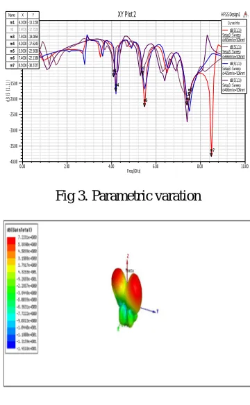
[image:4.612.214.394.416.708.2]Comparasion at different value of W and L
Fig 3. Parametric varation
Fig. 3 3D view of gain polar plot.
0.00 2.00 4.00 6.00 8.00 10.00
Freq [GHz] -37.50 -25.00 -12.50 0.00 d B (S (1 ,1 )) HFSSDesign1
XY Plot 3 ANSOFT
m1
m2 m3
m4 Curve Info
dB(S(1,1)) Setup2 : Sw eep1
Name X Y
m1 4.2000 -17.3800
m2 5.5000 -22.6861
m3 7.4000 -21.9747
m4 8.5000 -36.4100
0.00 2.00 4.00 6.00 8.00 10.00
Freq [GHz] -40.00 -35.00 -30.00 -25.00 -20.00 -15.00 -10.00 -5.00 0.00 5.00 d B (S (1 ,1 )) HFSSDesign1
XY Plot 2 ANSOFT
m1 m2
m3 m4
m5 m 6
m 7 Curve Info
dB(S(1,1)) Setup3 : Sw eep d='65mm' e='105mm'
dB(S(1,1)) Setup3 : Sw eep d='66mm' e='105mm'
dB(S(1,1)) Setup3 : Sw eep d='65mm' e='106mm'
dB(S(1,1)) Setup3 : Sw eep d='66mm' e='106mm'
Name X Y
m 14.1000 -13.1158
m2 5.4000 -12.3526
m 37.5000 -19.0855
m 44.2000 -17.6243
m 55.5000 -22.5830
m 67.4000 -22.1186
[image:4.612.217.395.424.545.2]Technology (IJRASET)
similar to that obtained for the U-slotted patch antenna [1], [3]. For antenna A, the impedance bandwidth, determined from a 10-dB return loss, is 4008 MHz or about 24.8% with respect to the center frequency at 2400 MHz, average of the measured lower and higher frequencies. with a 10-dB return loss. For antenna B, the obtained bandwidth is 3376 MHz or about 23.6% referenced to the center frequency at 5592 MHz. Radiation characteristics of the antenna are also studied. Fig. 3 plots three different operating frequencies for antenna A, which are all of same polarization planes and similar radiation patterns. The cross-polarization radiation in the E-plane patterns is also seen to be less than 20 dB. The H-plane patterns, however, show relatively larger crosspolarization radiation. This behavior is also similar to that reported forthe U-slotted patch [1], [3], and is largely due to the thick substrate thickness (about 0.08 times the wavelength of the center frequency in this study) and long probe pin in the substrate layer. Measured radiation patterns for antenna B (not shown here for brevity) also show similar results. Measured antenna gain for frequencies within the impedance bandwidth is also presented in Fig 3. For both antennas A and B, the antenna gain variation is seen to be less than 0.8 dBi, with the peak antenna gain at about 7.2 dBi. Finally, the excited patch’s surface current distribution of the proposed antenna is also studied by using HFSS. Fig. 3 shows the simulated patch’s surface current distribution for antenna A. Results for three typical frequencies at 4485, 5644, and 8540 MHz are shown. It is seen that all the three frequencies have similar surface current distributions on the rectangular patch. This characteristic agrees with the results that similar radiation patterns for the three frequencies are measured (see Fig. 3).
REFERENCES
[1] [1] K. F. Lee, K. M. Luk, K. F. Tong, S. M. Shum, T. Huynh, and R. Q. Lee, “Experimental and simulation studies of the coaxially fed U-slot rectangular path antenna,” Proc. Inst. Elect. Eng. Microw. Antennas Propagat., vol. 144, pp. 354–358, 1997.
[2] T. Huynh and K. F. Lee, “Single-layer single-patch wideband microstrip antenna,” Electron. Lett., vol. 31, pp. 1310–1312, 1995.
[3] K. L. Wong and W. H. Hsu, “Broadband triangular microstrip antenna with U-shaped slot,” Electron. Lett., vol. 33, pp. 2085–2087, 1997. G. Kumar and K. C. Gupta, “Directly coupled multiple resonator wide-band microstrip antenna,” IEEE Trans. Antennas Propagate., vol. AP-33, pp. 588–593, June 1985.
[4] D. M. Pozar , “Microstrip antenna coupled to a microstrip-line,” Electron. Lett., vol. 21, no. 2, pp. 49–50, Jan. 1985.
[5] K. L. Virga and Y. Rahmat-Samii, “Low profile enhanced-bandwidth PIFA antennas for wireless communications packaging,” IEEE Trans.Microwave Theory Tech., vol. 45, pp. 1879–1888, Oct. 1997.
[6] I. Papapolymerous, R. F. Drayton, and L. P. B. Katehi, “Micromachined patch antennas,” IEEE Trans. Antennas Propagate., vol. 46, pp. 275–283, Feb. 1998. [7] N. Herscovici, “New considerations in the design of microstrip antennas,” IEEE Trans. Antennas Propagat., vol. 46, pp. 807–812, June1998.