FEA Study of Pre-Fill Valve
Vishwanath S Kanal1
1Assistant Professor, BLDEA CET Vijayapur
Abstract: Pre-fill valve is Pilot-operated check valve which is designed to permit free flow in one direction and to block return flow, unless pilot pressure is applied. However, under pilot pressure, flow is permitted in both directions. In hydraulic systems, it is used as a pre-fill valve to permit the main ram to be pre filled during the “fast approach” cycle of a system operation.The main objective of this work is to design and analyze the different components of high pressure pre-fill valve based on the specifications and type of applications. The development of high pressure pre-fill valve is needed mainly for pre filling the main ram of high capacity hydraulic presses such as extrusion, forging, lamination, metal working, rubber molding presses during their fast approach operation and many other heavy duty applications. Pre-fill valve design is based on the pressure and temperature ratings i.e. operating pressure and temperatures. Industrial pre-fill valves are available in different Nominal sizes ranging from NG 25 – NG 200 for a working pressure below 35 MPa. Finite Element Analysis (FEA) is carried out for all the critical components/parts of this high pressure pre-fill valve by using the analysis software. Here ANSYS software has been used to carry out the FEA, which uses finite element method for solution. The methodology followed in this work is comparisons between the Analytical and Finite Element Analysis results.
Keywords— Prefill valve design, modelling, Analysis
I. INTRODUCTION
The main objective of the study is to design the critical components of the sandwich type pre-fill valve for an operating pressure of 42 MPa and the size Equivalent to NG 200. Conventional sandwich pre-fill valves are available up to operating pressure of 31.5 MPa and size of NG 150. Stresses in intricate areas of the valve components are difficult to calculate using conventional formulae and methods. The FEA will more accurate picture in these areas. It will also help in optimizing these areas for better stresses, better machining and better flow paths.
III.MAINPARTSOFAHIGH-PRESSUREPRE-FILLVALVE
The high pressure pre-fill valve consists of different parts which are assembled together to have the final assembly of the valve. Some parts of the valve, which are most important and for which the design is carried out are, pilot piston for applying the pilot pressure, valve poppet for flow control depending upon the system pressure, main spring for the popper to operate in the valve, pilot spring for the pilot piston, valve seat in a valve body etc. The Fig.2 shows all the necessary parts of a typical high pressure pre-fill valve.
fig.2 Parts of a high-pressure pre-fill valve
Dimensions of Prefill Valve
The designing of the valve starts with the design of the body. Body design is the crucial part of the entire design, because designs of many other parts are depending on the design of the body
Diameter of Pilot Cylinder Bore d=95mm Diameter of Poppet Stem d= 25mm
Diameter of Poppet Seat Diameter d =205mm
Poppet Disc Thickness t = 37 mm Seat Length a=5mm
Seat thcikness T=18mm
Fig.3 Cross sectional view of a valve seat
IV.FINALDIMENSIONSOFAVALVESEATANDPOPPET
During pre-filling the main cylinder of a heavy duty hydraulic press, due to the difference in pressure between supply tank which is at atmospheric pressure and the main cylinder, the oil will flow from supply tank into the main cylinder through pre-fill valve. Since the oil passes through pre-fill valve, apart from the calculated dimensions some profiles are also added to different of a valve components in order to have a smooth flow of oil when it passes through the pre-fill valve. Fig. 3.8 shows the dimensioned & profiled 2D sketch of a valve seat and the poppet.
fig.4 Final dimensions of valve seat and the poppet
V. ANALYSISOFVALVEPOPPET
Figure.5 Finite Element model of a poppet
Fig.6 deformation result of poppet Fig.7 Vonmises stress distribution in poppet
Figure.8 Graph of Number of Nodes Vs. Maximum bending stress
From above analysis results it is observed that the maximum bending stress induced due to a pressure of 42 MPa is 636.598 MPa, which is greater than the yield strength (578 MPa) of valve material selected. This is because of fixing the all degree of freedom on area which rests on the seat when the poppet is closed. But in actual condition which is not true. Therefore, the stresses of nodes near to the boundary which is showing maximum bending stresses are seen randomly and there average is taken. Fig.9 shows the bending stresses of randomly chosen nodes near to the boundary showing maximum stresses.
Figure.9 Bending stresses at randomly chosen nodes
The values of stress on randomly chosen nodes are 225.797, 237.017, 234.333, 234.659, 221.331, 235.297, 242.932, 235.647, 230.553 and 226.928 MPa.
Therefore, average bending stress is
10 226.928 230.553 235.647 242.932 235.297 221.331 234.659 234.333 237.017
225.797
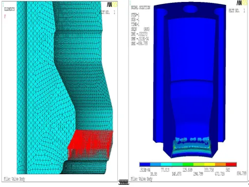
Fig.10 show the meshed solid model of a valve body with a applied force of F/8 on the seat area and analysis results of a valve body respectively.
Fig .10 FE model of a valve body with force applied on valve seat fig.11 Von-Mises stress distribution in valve seat
From fig.11 analysis results it is observed that the maximum bending stress induced due to applied force is 694.799 MPa, which is greater than the yield strength (578 MPa) of valve material selected, this stress is seen only at the ends of the model. But from figure it can be clearly observed that the bending stress in valve body is not exceeding the allowable stress i.e. 231.2 MPa except those two end corners. Hence the valve body and the seat are safe under bending.
VII. CONCLUSION
The present study involves the design of high pressure pre-fill valve as per the customer requirements for industrial applications. That is, the design is carried out for a valve operating pressure of 42 MPa and pilot cylinder operating pressure of 15 MPa. The analysis is carried out in ANSYS for some critical parts of the valve, comparisons are made between allowable stress of a valve material and ANSYS results and the following conclusions can be derived. The seat designed for the valve body is capable of taking the desired working pressure. That is, the maximum bending stress induced in a valve body for a specified operating pressure (42 MPa) is well within the allowable stress of a valve material.
[2] Industrial Hydraulic Systems and Circuits, By Bhagwati Prasad Gupta, pp 8,132.
[3] Oil Hydraulics Systems, Principles and Maintenance, S. R. Majumdar, Thirteenth Reprint 2006, pp 1-4, 13.
[4] Module – 6, Actuators, Lesson - 24, Directional Control Valves, Switches and Gauges, Version 2 EE IIT , Kharagpur, pp 3 – 6. [5] HAWE Hydraulik catalogue, Check Valves and Pre-fill Valves, D 6960.
[6] Steel Hand Book, Carbon, Stainless, Tool and Alloy Steel, German Standard Specifications, Edition 2002 – 2004. [7] Design Data Hand Book, for Mechanical Engineers, K. Mahadevan, K. Balaveera Reddy, Third Edition, Reprint 2005. [8] Machine Design, R. S. Khurmi, J. K. Gupta, Reprint 2005, pp. 537 – 540.
[9] Indian Standard “Steel Wire for Mechanical Springs Specifications”, Part-2, Oil Hardened and Tempered Steel Wire, Second Edition, IS: 4454 (Part 2) : 2001. [10] Indian Standard “Helical Compression Springs”, Part-1, Design and Calculations for Springs Made From Circular Section Wire and Bar, IS: 7906 (Part 1) –