System in Hydraulic Hybrid City Bus
Xunming Li, Jinyu Qu, Wei Wei, Xiangyu Tian
School of Transport and Vehicle Engineering, Shandong University of Technology, Zibo, China Email: [email protected]
Received 23 April 2014; revised 23 May 2014; accepted 28 May 2014
Copyright © 2014 by authors and Scientific Research Publishing Inc.
This work is licensed under the Creative Commons Attribution International License (CC BY).
http://creativecommons.org/licenses/by/4.0/
Abstract
In order to solve the coupling problem of power in Hydraulic Hybrid City Bus (HHB), a hydraulic hybrid power coupling system based on planetary gear transmission principle is proposed in this paper. The system consists of diesel engine, power coupler, hydraulic pump/motor, etc. The rea-lizable operating modes of power coupling system are analyzed in this paper. Under coordination of clutches, the engine driven mode, hydraulic driven mode, hybrid driven mode, hydraulic engine- start mode and braking energy recovery mode are realizable. Based on Lagrange equation, kinetic analysis and kinematics analyses are presented. In addition, the simulation model of the power coupling system is proposed, which includes diesel engine model, power coupler model, hydraulic pump/motor model, etc. The example simulation analysis is proposed under the hybrid driven mode; the results show that the power coupling system proposed in this paper can realize power coupling of hydraulic hybrid city bus. Compared with traditional city bus, the hydraulic hybrid city bus can choose small-displacement engine so as to improve fuel economy and dynamic property.
Keywords
HHB; Power Coupling System, Planetary Gear Trans, Hydraulic Starting
1. Introduction
Many scholars have researched the power coupling problem of the hydraulic hybrid bus, and some achieve-ments were achieved. Wojnarowski, Sherman and Wojnarowski J. proposed the bond graph model of epicyclical gear transmission and planetary gear transmission. The methodology of gear system kinetic analysis and kine-matics analysis are developed based on graph theory [2]-[4]. Guoqi He and L. W. Tsai proposed power coupling system of hybrid bus based on planetary gear transmission, and the lever analogy was used to analyze the speed characteristic and torque characteristic of power coupling system [5] [6]. The results show that many operating modes of hybrid bus can be realized by planetary gear transmission system.
A power coupling system of hydraulic hybrid bus is proposed in this paper, based on epicyclical gear trans-mission. Many operating modes of hydraulic hybrid city bus were realized by cooperation of many clutches. The power coupling system was used on the Yu Tong ZK6126HG city bus, and the coupling property under hybrid driven mode was analyzed. Diesel engine model, hydraulic accumulator model and hydraulic pump/motor mod-el were established; in addition, the mathematic modmod-el of coupler based on Lagrange equation was established. All the models were simulated under Matlab/Simulink simulation environment. The results show that the power coupling system can solve the power coupling problem of the hydraulic hybrid bus effectively, and the vehicle dynamic property improved obviously under the same fuel consumption.
2. Design of Power Coupling System
This paper studies a power coupling system applied to hydraulic hybrid city bus.Figure 1 shows the schematic diagram of power coupling system. The power coupling system is made up of engine and epicyclical gear transmission integrated with a hydraulic motor that can also function as a hydraulic pump. In the figure, the power coupler is set between engine crankshaft and engine flywheel. The engine crankshaft is connected to the sun gear of power coupler, and the sun gear can be integrated or separated with planet carrier by clutch C1. The output shaft of hydraulic motor is connected to the gear ring of power coupler by clutch C2. The output shaft of power coupler or the output shaft of planet carrier of power coupler is connected to the transmission of the ve-hicle. In follows, the component models are built and the characteristic of the power coupling system is ana-lyzed.
3. Operating Modes of Power Coupling System
The hydraulic hybrid city bus drives on certain mode based on different driving cycle, and realizes energy con-servation and emission reduction with braking energy regeneration.
3.1. Engine Driven Mode
To launch the vehicle from a standstill and for driving in city traffic, the clutch C1 is engaged and the clutch C2 is disengaged. At this time, the sun gear integrated with planet carrier, and the transmission ratio between engine and transmission is one. The engine is used to drive the city bus, individually, and the dynamic property of the city bus is not influenced compared with the traditional city bus. The power transmission line is shown inFigure 2. In the follow figures of this paper, the clutch of black color indicates that the clutch is engaged and the clutch of white color indicates that the clutch is disengaged.
3.2. Hydraulic Driven Mode
Hydraulic accumulator has the advantage of higher power density and the ability to accept the high rates and high frequencies of charging and discharging, both of which are not favorable for batteries [7]. As a result, the hydraulic hybrid city bus stores the braking energy in the hydraulic accumulator as a form of hydraulic energy. When the hydraulic hybrid city bus works on the starting or climbing conditions, the hydraulic energy is trans-lated to the kinetic energy of the bus to reach the purpose of energy conservation and emission reduction. Figure 3
shows the power transmission line of hydraulic driven mode.
Figure 1. The schematic diagram of power coupling system.
Figure 2. Power transmission line of engine driven mode.
Figure 3. Power transmission line of hydraulic driven mode.
re-gion is reached.
3.3. Hybrid Driven Mode
Simpson planet gear mechanism belongs to 2K-H type epicyclical gear transmission, which has two degree of freedom when all elements are flexible [9]. Two input torques can be synthesized to one output torque at advan-tage of this feature. If the hydraulic hybrid city bus running in hybrid driven mode, clutch C2 should be engaged while clutch C1 should be disengaged. The power transmission line of hybrid driven mode is shown in Figure 4. The engine power and the hydraulic motor power synthesized in the power coupler, and then output to transmis-sion to drive the city bus. Hydraulic energy storage system features high frequency response, high power density, simple system structure, compatible technology and remarkable energy-saving and emissions reduction effect
[10]-[13]. Under the working condition of starting or climbing, some auxiliary power can be added to the hy-draulic hybrid city bus to improve the dynamic property, and ensure that the engine works in the economy re-gion, which is helpful to reduce fuel consumption and emission.
3.4. Hybrid Driven Mode
Two engine hydraulic start modes are proposed by the power coupling system: standstill hydraulic start and dy-namic hydraulic start. The standstill hydraulic start is that the bus hydraulically starts when the hydraulic accu-mulator pressure is low. The hydraulic energy is released from the hydraulic accuaccu-mulator and translated to me-chanical energy by hydraulic motor, and then drive the engine to idling speed. The dynamic hydraulic start works when the hydraulic accumulator pressure is high. At this time, both clutch C1 and C2 should be engaged, and the transmission is in a non-neutral state. The city bus and engine are droved by hydraulic motor in the meantime. Clutch C2 is disengaged, and the engine is started by the inertia of the city bus, when the end of the hydraulic energy release. The power transmission line of engine hydraulic start mode is shown in Figure 5.
The engine hydraulic start mode reduces fuel consumption and emission during the engine start, and then the engine works in an economy region. Compared with the traditional way of engine start, higher torque can be output, and engine cannot be influenced by temperature at the engine hydraulic start mode.
3.5. Braking Energy Recovery Mode
Hydraulic braking force and mechanical friction braking force can be distributed reasonably, depending on the demand of braking intensity of power coupling system.
Under the condition of low braking intensity, clutch C2 is engaged and clutch C1 is disengaged. The hydrau-lic braking works alone, all of the braking energy is recovered into the hydrauhydrau-lic accumulator.
Under the condition of middle braking intensity, clutch C2 is engaged and clutch C1 is disengaged. The hy-draulic braking and the mechanical braking combine to work, and most of the kinetic energy is recovered into the hydraulic accumulator. This mode can not only recycle the braking energy but also reduce the braking inten-sity, which prolongs the life of the braking. Figure 6 shows the power transmission line of braking energy re-covery mode under low and middle braking intensity.
Under the condition of high braking intensity, both clutch C1 and clutch C2 are engaged. Hydraulic pump, engine and mechanical braking work to decelerate the city bus. The power transmission line of braking energy recovery mode under high braking intensity is shown in Figure 7. When the bus is driving on slippery roads or steep roads, the braking energy recovery mode can avoid using the mechanical braking frequently [14]. Ob-viously, this mode is helpful to prolong the life of braking discs, slow down heat fade and water fade, and im-prove the braking efficiency and safety of the city bus.
4. Characteristic Analysis of Power Coupling System
4.1. Kinematics Analysis of Power Coupling System1) Speed calculation of planet carrier of the power coupler
The conversion of the epicyclical gear train is the ordinary fixed axis gear train, and the method solving transmission ratio of fixed axis gear train can be used to calculate transmission ratio of epicyclical gear train
Figure 4. Power transmission line of hybrid driven mode.
[image:5.595.170.458.521.692.2]Figure 5. Power transmission line of engine hydraulic start mode.
Figure 7. Power transmission line of braking energy recovery mode under high braking intensity.
ring and the sun gear is shown as Equation (1). H
s s H
H
r H
r
n n n
n n
n β
−
= = −
− (1)
where β is the transmission ratio between sun gear and ring gear, relative to the planet carrier; nsH is the speed
of sun gear, relative to the planet carrier; nrH is the speed of gear ring, relative to the planet carrier; nris the
actual speed of gear ring; ns is the actual speed of sun gear; and nH is the actual speed of planet carrier.
From Equation (1), we have
(
1)
0sRs rRr HRH
ω +βω − +β ω = (2)
where ωs is the angular speed of sun gear; ωr is the angular speed of gear ring; ωH is the angular speed of planet
carrier; RHis the radius of planet carrier; Rs is the radius of sun gear; and Rris the radius of gear ring.
From Equation (2), we have the angular speed of planet carrier of the power coupler:
(
1)
(
1)
s r
H s r
H H
R R
R R
β
ω ω ω
β + β
+ +
= (3)
2) Speed calculation of planet gear of the power coupler
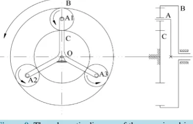
As shown in Figure 8, assume the gear ring of the power coupler holds still, calculate and analyze the relation between the sun gear and the planet gear.
The motion of any point in the plane graphics can be regard as synthesis of the two movements, and the speed of any point can be calculated depend on speed synthesis theorem [16]. Angular speed is a vector and the defini-tion of plus and minus are described below: from the positive end of the shaft, if the rigid body is turning coun-terclockwise, the angular speed takes the positive value, otherwise, the negative value. Assume A as the basic point, the speed relation between the sun gear and the planet gear is:
C A CA
u =u +u (4)
where μCand μA is the linear speed of point C and A, respectively; μCA is the speed of point C relative to point A.
From Equation (4), we have the angular speed relation of sun gear, planet carrier and planet gear:
s Rs H RH p Rp
ω ⋅ =ω ⋅ −ω ⋅ (5)
where ωp is the angular speed of planet gear; Rpis the radius of planet gear.
As shown in Figure 9, assume the sun gear of the power coupler holds still; calculate the speed relation be-tween the gear ring and the planet gear.
[image:6.595.171.458.86.251.2]Figure 8. The schematic diagram of the sun gear driv- ing the planet carrier.
Figure 9. The schematic diagram of the gear ring driv- ing the planet carrier.
B A BA
u =u +u (6)
where μB is the linear speed of point B; μBA is the speed of point B relative to point A.
From Equation (6), the angular speed relation of gear ring, planet carrier and planet gear is:
r Rr H RH p Rp
ω ⋅ =ω ⋅ +ω ⋅ (7)
From Equation (5) and Equation (7), the angular speed of planet gear is:
2 2
s r
p r s
p p
R R
R R
ω = ω − ω (8)
4.2. Kinetic Analysis of Power Coupling System
Take the angular displacement of crankshaft (θs) and the angular displacement of the hydraulic motor output
shaft (θr) as the generalized coordinates. The relative angular speed is the generalized angular speed, that is
s s
θ =ω , θr=ωr. The kinetic energy of the power coupling system is:
2 2 2 2 2 2
1 1 1 1 3
2 s s 2 H H 2 r r 2 p p 2 p H H
E= Jθ + J θ + Jθ + J θ + m ⋅R ⋅ω (9)
where Jsis the moment of inertia of the engine output shaft and its pontes; JHis the moment of inertia of the
transmission output shaft and its pontes; Jris the moment of inertia of the pump motor output shaft and its
pontes; Jp is the moment of inertia of the planet wheel of the power coupling system; mp is the mass of the planet
gear.
From Equation (3), (8), (9), we have Equation (10):
2 2
11 12 22
1 1
2 s s r 2 r
[image:7.595.215.413.253.380.2]where
(
)
(
)
2 2 2 2 11 31 2 1
s s s
s H p p H
H p H
R R R
J J J J m R
R R R
β β + + + + +
= (11)
(
)
( )
(
)
2
12 2 2 3 2
1 2 1
s r s r s r
H p p H
H p H
R R R R R R
J J J m R
R R R
β β β β = − + + + (12)
(
)
(
)
2 2 2 2 22 31 2 1
r r r
r H p p H
H p H
R R R
J J J J m R
R R R
β β β β + + + + +
= (13)
The generalized force corresponded to θs and θr is torque, the power of all external force is:
s s H H r r
P T= ⋅ω +T ⋅ω + ⋅T ω (14)
where Tsis the output torque of engine; Tr is the output torque of hydraulic motor; TH is the input torque of
transmission.
From Equation (3) and Equation (14), the power of external force is:
(
1)
(
1)
s H r H
s s r r
H H
R T R T
P T T
R R β ω ω β β ⋅ = + ⋅ + + ⋅ + +
(15)
The generalized force corresponded to θs and θr is:
(
1)
rr r H
H
R
Q T T
R
β β
= +
+ (16)
(
1)
ss s H
H
R
Q T T
R
β
= +
+ (17)
5. Mathematical Model of Power Coupling System
5.1. Model of the Power CouplerThe Lagrange equation [17], named after Joseph Louis Lagrange, is an important equation of Lagrange me-chanics. The Lagrange equation can be used to describe the movement of object. Put the generalized force into the Lagrange equation, we have:
11 12 12 22 s s r r Q J J
J J Q
θ θ =
(18)
Aliased as
=
Jα T (19) where J is the moment of inertia of the components of the planet gear; α is the acceleration matrix of the sun gear and the gear ring; T is the generalized force matrix.
Equation (19) is the model of the power coupler, solve Equation (19), we have the relation of the engine tor-que, the hydraulic motor torque and the output torque of the power coupler.
From Equation (5) and (7), the coupling model of the power coupler is:
2ωHRH=ωsRs+ωrRr (20)
5.2. Diesel Engine Model
Figure 10. Engine universal characteristics curve.
and Power Trains Laboratory at the Shandong University of Technology.
The instantaneous engine torque is approximately decided by the following equation:
( )
max( )
e e
T w =µT w (21)
Here, u is a nominal control signal adjusting the engine throttle position and therefore determines the engine torque output. The values of u are in the domain [0, 1], with 0 and 1 indicating closed throttle and wide-open- throttle position, respectively. Temax
( )
w is the maximum available engine brake torque which is the function of the engine speed and described by the lookup table of wide-open-throttle engine brake toque.5.3. Hydraulic Pump/Motor Model
When the bladder accumulator in application, the medium (nitrogen gas) can be regarded as a single thermody-namic system and the working process of bladder accumulator is regarded as the process that the single thermo-dynamic system translates energy with surrounding [18]. From Boyle’s gas law, we have
( )
max 0 0 1 1 2 2
n n n
e
T w p V = p V = p V =const (22)
where V0, V1, and V2is the gas volumes under the pressure p0, p1and p2, respectively; n is the polytrophic expo-nent, and n takes one at the process of isothermal change or takes one point four at the process of adiabatic change.
The relation of the accumulator pressure and the hydraulic pump/motor torque is:
( ) sgn 2π e T g m V p
M= ⋅ ∆ ⋅η (23)
where Vg is the accumulator displacement; ∆p is the pressure variation of the accumulator; ηm is the mechanical
efficiency of the hydraulic system.
5.4. Hydraulic Accumulator Model
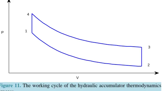
The hydraulic accumulator is an important component of storing energy as a secondary power source for parallel hydraulic hybrid vehicle. In this way, accumulator is similar, in function, to the counterpart of electric batteries in the electric hybrid vehicles. Figure 11 shows the thermodynamics process of a hydraulic accumulator charge and regenerate braking energy. Where, p and V is the gas pressure and specific volume, respectively.
The process 1 to 2 shows that hydraulic accumulator release gas energy and increase volume, the process 3 to 4 shows that hydraulic accumulator store gas energy and decrease volume. Both the process 1 to 2 and the process 3 to 4 are finished instantaneously and for modern bladder accumulators, the higher cycle rates and the application of elastomeric foams on the inner bladder wall lead to little or no heat transferred into or out of the
800 1000 1200 1400 1600 1800 2000 2200
200 300 400 500 Speed (r/min) 200 204 209 211 213 215 217 219 222 224 226 228 230 232 234 237 239 241 243 245 247252 2525624 28.2
39.6 51
Figure 11. The working cycle of the hydraulic accumulator thermodynamics process.
accumulators, so we should assume that the compression and expansion of gas is adiabatic. The process 2 to 3 and the process 4 to 1 are the isometric process. Gas temperature returns to ambient temperature. The dynamic accumulator model is based on the following equation:
n
pV =C (24)
Here, p is supply pressure; V is gas volume; n is polytrophic index within a range between 1 (isothermal process) and 1.4 (adiabatic process); C is constant and depends on pre-charge pressure.
Derivative the Equation (24) on both sides, we get:
1
d d
d d
n
n
V V p
t = −npV − ⋅ t (25)
From the Equation (25) and Equation (26) we get:
1/
1 1/
d 1 d
d d
n
n
V C p
t = − n ⋅p+ ⋅ t (26)
where, the minus indicates that when the pressure of hydraulic accumulator increases, the gas volume in the in-ner bladder of the hydraulic accumulator decreases.
For a hydraulic accumulator, if we ignore the change of the quality and the volume of the hydraulic oil, the fluid volume that into and out of hydraulic accumulator equal to the change rate of the gas volume of bladder in the hydraulic accumulator. We get:
d d
a
V Q
t
= (27)
6. Simulation and Analysis of the Results
The simulation model can be established according to the mathematical model of the power coupling system under Matlab/Simulink. Copy relative functional modules to the simulation environment; connect each block diagram according to the flow direction of the signal, create a signal source, and then assign simulation results to relative variables, and finally draw curves in workspace.
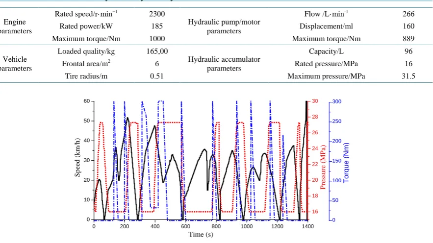
In the simulation model, the input torque of the power coupler is the engine output torque under China typical city bus driving cycle. To keep the high efficiency, the solver is the key. Variable step size 4 order 5 order Runge-Kutta algorithm (ode 45) is employed according to the simulation model of the coupler. The parameters of the test vehicle are shown in Table 1.
Figure 12 shows China typical city bus driving cycle, which is established depending on Recommended Practice for Measuring Fuel Economy and Emissions of Hybrid-Electric and Conventional Heavy Duty Vehicles (SAEJ2711). The pressure change of hydraulic accumulator under China typical city bus driving cycle, and the hydraulic motor output torque while the releasing its energy under China typical city bus driving cycle are also
1
2 3 4
P
0 200 400 600 800 1000 1200 1400 0
10 20 30 40 50 60
Torque
(N
m)
P
ressu
re (
MP
a)
S
pe
ed (
km
/h)
Time (s)
16 18 20 22 24 26 28 30
0 50 100 150 200 250 300
Figure 12. Driving cycle curve, accumulator pressure curve, and accumulator pressure curve.
should in the Figure 12. From the curves, we know that hydraulic accumulator and hydraulic motor can supply high instantaneous torque, which can be used to improve the dynamic property while the hydraulic hybrid city bus under the conditions of acceleration and climbing.
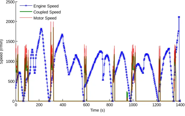
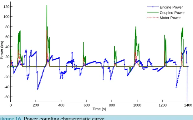
Figure 13 shows the desired torque. The torque coupling property, speed coupling property and power coupling property of the power coupling system is shown in Figure 14, Figure 15 and Figure 16, respectively. As shown in the curves, the power coupling system, proposed in this paper, can solve the coupled problem of the hydraulic hybrid city bus effectively. The low-powered engine can be taken while the hydraulic motor is the auxiliary power, then the engine work in the economic fuel consumption region to improve the fuel economy and emission performance.
From these figures, one can see that the power coupling system played an important role when the vehicle in the climbing condition. At this time, stored accumulator energy is used to supply much of the power demand, with the engine being used to supply short bursts of power. For the certain power demand, the large displace-ment engine can be replaced by a little one, and the remaining power added by the hydraulic motor. Therefore, the purpose of energy conservation and emission reduction can be achieved.
Furthermore, the power of hydraulic motor is supplied by the hydraulic accumulator, when the accumulator at the low energy, all power should be present by engine, and there will be high fuel consumption. To solve this problem, a cooperation strategy between engine and hydraulic motor should be designed.
7. Conclusions
1) This paper proposed a power coupling system of the hydraulic hybrid city bus, and analyzed the operating modes of the system.
2) Kinetic analysis and kinematics analysis of the power coupler under hybrid driven mode were presented. The models of engine, hydraulic accumulator and hydraulic pump/motor were established, and the mathematical model of power coupler was built, based on Lagrange equation.
[image:11.595.97.539.94.342.2]Figure 13. Vehicle demand torque curve.
Figure 14. Coupling torque characteristic curve.
Figure 15. Speed coupling characteristic curve.
0 200 400 600 800 1000 1200 1400
-800 -600 -400 -200 0 200 400 600 800
Time (s)
T
or
que (
N
m
)
0 200 400 600 800 1000 1200 1400
-1000 -800 -600 -400 -200 0 200 400 600 800 1000
Time (s)
T
or
que (
N
m
)
Engine Torque Coupled Torque Motor Torque
0 200 400 600 800 1000 1200 1400
0 500 1000 1500 2000 2500
Time (s)
S
peed (
r/
m
in)
[image:12.595.158.467.511.705.2]Figure 16. Power coupling characteristic curve.
Acknowledgements
This research is supported by the National Natural Science Foundation of China (Grant No. 51275280) and Shandong Province Science and Technology Development Program (Grant No. 2011GGX10505).
References
[1] Deppen, T.O., Stelson, K.A., Meyer, J.J. and Alleyne, A.G. (2012) Optimal Energy Use in a Light Weight Hydraulic Hybrid Passenger Vehicle. Journal of Dynamic Systems, Measurement, and Control, 134, 041009.
http://dx.doi.org/10.1115/1.4006082
[2] Wojnarowski, J., Kopeć, J. and Zawiślak, S. (2006) Gears and Graphs. Journal of Theoretical and Applied Mechanics,
44, 139-162.
[3] Lang, S.Y. (2005) Graph-Theoretic Modeling of Epicyclic Gear Systems. Mechanism and Machine Theory, 10, 511- 529. http://dx.doi.org/10.1016/j.mechmachtheory.2004.12.001
[4] Wojnarowski, J. and Lidwin, A. (1975) The Application of Signal Flow Graphs—The Kinematic Analysis of Planetary Gear Trains. Mechanism and Machine Theory, 10, 17-31. http://dx.doi.org/10.1016/0094-114X(75)90054-3
[5] Benford, H.L. and Leising, M.B. (1981) The Lever Analogy: A New Tool in Transmission Analysis. SAE Technical Paper No. 810102.
[6] Tsai, L.W., Schultz, G. and Higuchi, N. (2001) A Novel Parallel Hybrid Transmission. Journal of Mechanical Design,
123, 161-168. http://dx.doi.org/10.1115/1.1365118
[7] Sun, H. (2010) Multi-Objective Optimization for Hydraulic Hybrid Vehicle Based on Adaptive Simulated Annealing Genetic Algorithm. Engineering Applications of Artificial Intelligence, 23, 27-33.
http://dx.doi.org/10.1016/j.engappai.2009.09.005
[8] Qin, D.T., You, G.P. and Hu, J.J. (2009) Operation Mode Analysis and Parameters Design of a Novel Power Split Hy-brid Transmission System. Chinese Journal of Mechanical Engineering, 45, 184-191.
http://dx.doi.org/10.3901/JME.2009.02.184
[9] Wei, Y.Y., Lin, Y. and He, H.W. (2005) The Applied Research on Double Row Planetary Gear Train for HEV. Auto-mobile Technology, 8, 11-14.
[10] Liu, T., Jiang, J.H., Sun, H. and Zhao, L.J. (2009) Research and Progress of the Hydrostatic Hybrid Vehicle. Automo-tive Engineering, 31, 586-591.
[11] Zhang, J., Luo, N.N. and Jiang, J.H. (2012) Research Survey of Hydraulic Hybrid Vehicles. Machine Tool & Hydrau-lics, 6, 67-79.
[12] Peng, D., Yin, C.L. and Zhang, J.W. (2006) Advanced Braking Control System for Hybrid Electric Vehicle Using Fuzzy Control Logic. SAE Paper No. 2006-01-3583.
[13] Chen, H.Z. and Yuan, S.H. (2003) Design of the Hydraulic System for Braking Energy Storage to City Vehicle. Chi-nese Hydraulics & Pneumatics, 4, 1-3.
[14] Yang, Y., Zhao, X.F., Qin, D.T., Duan, Z.H. and Gong, H. (2012) Design and Operation Mode Coupling
Characteris-0 200 400 600 800 1000 1200 1400
-60 -40 -20 0
tics Analysis on the New Transmission System of Hybrid Electric Vehicle. Automotive Engineering, 34, 968-975.
[15] Yang, K.Z., Cheng, G.G. and Li, Z.S. (2009) Fundamentals of Machine Design. Higher Education Press, Beijing. [16] Theoretical Mechanics Research Group of Harbin Institute of Technology (2009) Theoretical Mechanics. Higher
Edu-cation Press, Beijing.
[17] Diao, Y.F., Wei, H.X. and Yang, E.X. (1999) The Application of Plane Unfolding Formula of Lagrange Equation in Mechanism Dynamics. Journal of Harbin Engineering University, 20, 91-96.