36
Chapter 3 A New Framework for
Multicast Mobility in WiFi Networks
3.1 Introduction
This chapter presents the designed framework that was produced during this research. The chapter describes about network architecture, protocol overview and the details of protocol process step by step.
3.2 Network Architecture
In this research, there is a requirement for a system that provides support for research scenarios in WiFi networks that are connected through the internet. According to the real world, the WiFi network will combine with an IP wired infrastructure network with a gateway router to route data through to the internet. There are a variety of clients in the network such as PCs, laptops and mobile devices [66].
37
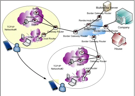
Figure 3-1 Network Architecture
Figure 3-1 is shown the stage which we consider WiFi to WiFi handover.
Here, the architecture comprises only WiFi networks that comprise: a media server which represents the source server, which is sending the multicast packets to mobile devices in the network. The rendezvous router is a central router in a multicast tree.
Border gateway router is a core router which is enabled for multicast delivery services and supports multicast routing protocols such as PIM (Protocol-Independent Multicast), MOSPF (Multicast Extensions to Open Shortest Path First), DVMRP (Distance Vector Multicast Routing Protocol) and so on.
Gateway router is a core router within a company network which is connected to both WiFi and wireline networks, providing Internet access and supporting multicast routing protocols.
Local router is a router that connects between a WiFi access point and other network devices in the local network.
38
Mobile nodes with embedded WiFi interface roam within this network.
3.3 Protocol Overview
In this section we will describe the process by which the new proposed framework is designed to improve handover performance for multicast services. Procedures and protocols already exist for handling handover from one WiFi network to another. However, such protocols, of which mobile IP is a key example, achieve handover by firstly making contact with a new WiFi base station, obtaining a new IP address and then re-routing traffic to that new address through a modified multicast tree. Unfortunately this leads to a loss of connectivity and hence, service whilst this process is taking place. Similarly, IGMP manages the distribution of multicast services through the establishment of a multicast tree which is maintained by the routers. When a mobile node, moves, this tree needs to be modified to accommodate the mobile node’s new location. This therefore leads to further delay which handover takes place. Our approach is to complete as much of the existing handover process as possible before the physical handover actually takes place. This therefore will minimise the actual handover delay at the expense of having to establish several connections to neighbouring networks, most of which may never be activated.
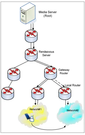
The overall concept of our new framework is that a mobile node will use mobile IP but modified in such a way as to allow connectivity to multiple foreign networks. In so doing a mobile node will receive a Care of Address from each foreign network that is within range. These addresses are then used to compute multiple extensions to the existing multicast tree, which are then held in a standby mode until required. The standby route represented as a dash line in Figure 3-2 below. Once a mobile node actually completes handover by moving to a new WiFi base station, the Care of Address that has already been obtained and the associated change to the multicast tree are then activated with traffic being routed to that mobile node via this new route.
39
[image:4.595.160.435.129.564.2]chapter it is shown how the new framework can be applied to a network that employs mobile IP and IGMP.
Figure 3-2 Multicast Route
3.4 Process Diagram
40 The outline of our process is as follows [67]:
The mobile device connects to the WiFi#1 as home network and receives a multicast data stream as usual.
The mobile device sends the message to join WiFi#2 as a foreign network in advance by modified Mobile IP protocol.
The mobile node uses its CoA address from WiFi#2 to establish a new multicast route with the same media server.
After it receives the multicast message from the second route, it disconnects the second route at a point along the path between its local router for WiFi#1 and the rendezvous router.
Local router of WiFi#2 network sends a modified PIM protocol message to keep its connection as a standby route.
If handover occurs then the modified ICMP protocol message will be sent to reconnect the second route. This will minimize handover delay because the second route has already been configured and just needs to switch from standby to active.
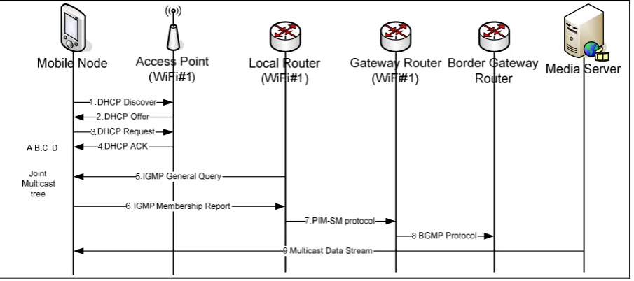
[image:5.595.74.527.486.687.2]Figure 3-3 is shown the initial steps of how a mobile node is able to register for receipt of a multicast stream being delivered by the media server.
Figure 3-3 Starting connection process
41
1. The mobile node sends a DHCP Discover to its local access point by broadcasting in order to discover the DHCP server that can supply it with an IP address.
2. In this case WiFi#1 will respond with a DHCP Offer including an IP address.
3. If the mobile node accepts that IP address, the mobile node will send a DHCP Request message including that IP address back to the access point for confirmation.
4. Access point WiFi#1 will send a DHCP ACK message back to the mobile and allow the mobile node access to the network. At this stage, the mobile node will has IP address for establish a connection to media server.
5. Usually, if a local router is enabled for multicast delivery it will send an IGMP General Query every 60 seconds within the network. Hence, at this stage WiFi#1 will send an IGMP General Query message out to the mobile node [68].
6. In this scenario, the mobile node wants to connect to the multicast tree and so it will send an IGMP Membership Report, including the IP multicast address to which it wants to connect.
7. The local router will then use its multicast routing protocol to connect to the appropriate multicast tree. In this case it will create a PIM-SM protocol message and send it to the gateway router within the WiFi#1 network.
8. Since in this case the media server is outside the local network and on the internet, BGMP will be used by the gateway router to connect to the multicast tree.
9. Once connected to the multicast tree, the mobile node will start to receive the multicast data stream.
42
Mobile IP
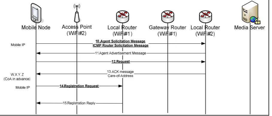
[image:7.595.74.529.73.267.2]Mobile IP
Figure 3-4 Request CoA address in advance process
Figure 3-4 is shown the process of obtaining a care of address in advance from access point WiFi#2 as the mobile node is preparing to move away from access point WiFi#1.
The procedure is described as follows:
1. When the mobile node received a signal from foreign agent which is Local Router on WiFi#2 network in Figure 3-4, that implies the mobile node is in range of foreign agent. In the new framework, we designed that the mobile node will broadcast a Mobile IP Agent Solicitation Message every 30 seconds for registering to the new foreign agent. This process Mobile IP does not use a new packet type for agent solicitation, it uses the router solicitation packet of ICMP.
2. After receiving Mobile IP Agent Solicitation Message, the local router (foreign agent) in the Wifi#2 network will send back an Agent Advertisement Message which includes the IP care of address (CoA) to the mobile node.
3. If the mobile node accepts this address, the mobile node will send a Request message to confirm to the local router in WiFi#2 network that it wants to use this IP address.
4. The local router will subsequently acknowledge this with an ACK message. At this stage, that means the mobile node had CoA address in advance before moving to WiFi#2 network. Also it means the mobile node can use this IP address if it handover into WiFi#2 network.
43
its Home agent which, in this case, is the local router in WiFi#1 network.
6. After the home agent stores the information in their database, it will send a Registration Reply to confirm to the mobile node. At this stage, the mobile node has two addresses; one is an IP address from its home agent and the other is the CoA address from the foreign agent.
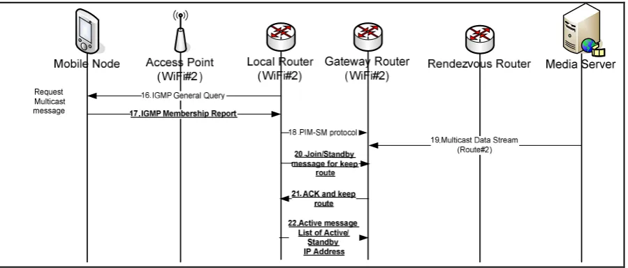
[image:8.595.75.525.257.449.2]The next strategy is to establish a new multicast route from the foreign network to the multicast tree, the details of which are shown in Figure 3-5.
Figure 3-5 Request Multicast packets and keep route
The procedure is described as follows:
1. Normally, the local router will broadcast an IGMP General Query to the client in their network which in this case is the local router in the WiFi#2 network. For querying that there is any client would like to join any multicast tree in network.
2. If the mobile node wants to join the multicast tree it will send an IGMP Membership Report including the IP multicast address to the local router. In this framework the mobile node will use the CoA address to communicate.
3. The local router will use the PIM-SM protocol to communicate with the gateway router in the WiFi#2 network for creating the route to multicast tree by connecting to rendezvous router.
44
local router. However, at this stage, there are two routes connected to the same multicast tree but only one should be live. Therefore, we are proposing to modify the PIM-SM message to keep the route between the local router in the WiFi#2 network and the gateway router in a standby mode.
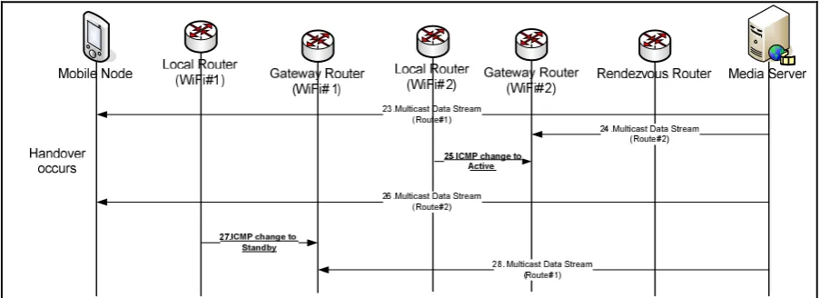
[image:9.595.72.524.299.463.2]
Figure 3-6 is shown details of the process when the handoff process occurs. The idea is to change the route at the foreign agent from standby to active. Here the secondary route which has been established using the CoA needs to be switched from standby to active and the currently active route which uses the home address needs to be switched from active to standby.
Figure 3-6 Handover process
The procedure for achieving this is as follows:
1. The local router in the WiFi#2 network will send a modified ICMP message to the gateway router to change mode from standby to action. This means that the new route for the multicast data stream is ready to connect. Moreover, this method should reduce handoff latency time.
2. After that the mobile node will start to receive multicast data stream via the new route. 3. The next step is to change the old route to standby mode by sending an ICMP change to Standby message to the gateway router in WiFi#1 network.
45 have setting timeout for delete route.
3.5 Modified Protocol Message
In this research, there are some protocol messages that have been modified to support our designing framework, which are:
3.5.1
PIM Protocol Message
[image:10.595.80.494.353.728.2]The message that we have been modified in PIM protocol is “Join/Prune message”. The format of Join/Prune message is shown in Figure 3-7. This message modified for keeping status join/standby message information which sends between local router in WiFi#2 and rendezvous router in the process number 20 in the Figure 3-5.
46
3.5.2
ICMP Message
[image:11.595.127.486.266.532.2]The ICMP message has been modified and adapted for controlling and changing the status of a second route when the handover happened. In our framework when handover occurs, local router in WiFi#2 will send the message to change the status to become active as in process number 25 in Figure 3-6. After that, the mobile node can continuously receive the multicast message from multicast tree without rebuilding the tree. We modified ICMP to support this strategy. The 3-8 is shown the standard ICMP message.
Figure 3-8 ICMP message format [35]
3.5.3
Mobile IP Message
47
Figure 3-9 Mobile IP message format [32]
3.5.4 IGMP Message
48
Figure 3-10 IGMP message format [6]
3.6 Summary
This chapter describes the network requirement, network architecture, the protocol process and modifying messages in detail. According to our goal we are trying to minimize the handover process in multicast mobile. The framework creates the reserve routes via neighbour zones, which are connected to the same multicast tree in advance. When handover occurs, the system only changes the status from standby to active and from active to standby mode.
![Figure 3-7 Join/Prune messages format [20]](https://thumb-us.123doks.com/thumbv2/123dok_us/8705992.880752/10.595.80.494.353.728/figure-join-prune-messages-format.webp)
![Figure 3-8 ICMP message format [35]](https://thumb-us.123doks.com/thumbv2/123dok_us/8705992.880752/11.595.127.486.266.532/figure-icmp-message-format.webp)
![Figure 3-9 Mobile IP message format [32]](https://thumb-us.123doks.com/thumbv2/123dok_us/8705992.880752/12.595.95.499.76.469/figure-mobile-ip-message-format.webp)
![Figure 3-10 IGMP message format [6]](https://thumb-us.123doks.com/thumbv2/123dok_us/8705992.880752/13.595.135.463.76.169/figure-igmp-message-format.webp)
