The University of Salford
School of Computing, Science and Engineering MSc by Research in Robotics
Design and Development of an Anthropomorphic
Metamorphic Robotic Hand
Dissertation submitted to the University of Salford in complete fulfilment of the requirements for the degree of Master of Science by Research in Robotics.
By Olegs Marcenko
@00370152
Supervisor Dr. Guowu Wei
1
Contents
The List of Figures... 3
The List of Schematics ... 4
Acknowledgements ... 7
Abstract ... 8
Chapter 1 ... 9
1.1. Introduction to Robotics ... 9
1.2. Objectives ... 11
Chapter 2 ... 12
2.1. Background of Commercial Hands ... 12
2.1.1. The i-Limb hands ... 13
2.1.2. Bebionic hands ... 14
2.1.3. Vincent Hand ... 14
2.1.4. Michelangelo Hand ... 14
2.1.5. DLR hands (Commercial) ... 15
2.1.6. BarrettHand ... 16
2.1.7. Body powered or electric fingers as partial hand options from Advanced Arm Dynamics 16 2.1.8. Robotiq adaptive gripper hands (2-3 fingers) ... 17
2.1.9. Comments ... 22
2.2. Review of Scientific Robotic Hands ... 23
2.2.1. Biomimetic anthropomorphic hand by Zhe Xu and Emanuel Todorov27 ... 24
2.2.2. DLR “David’s” Hand ... 25
2.2.3. Elu-2 Hand ... 25
2.2.4. KCL 3-finger metahand ... 25
2.2.5. Modular soft robotic gripper37 ... 26
2.2.6. RBO Hand 238,39 ... 26
2.2.7. Multifingered metamorphic hand by G. Wei et. al.40 ... 27
2.2.8. The Robonaut Hands41,42 ... 27
2.2.9. UB Hand IV ... 29
2.2.10. The SmartHand44 ... 30
2.2.11. The Shadow Hand46,47,48,49 ... 30
2.2.12. Comments ... 33
2.3. Summary ... 33
Chapter 3 ... 35
2
3.2 Design Overview ... 36
3.3 Grasping Capabilities ... 42
3.4 Summary ... 47
Chapter 4 ... 48
4.1. Introduction ... 48
4.2. Preliminary Theory ... 48
4.2.1. Orientation and Translation. Position in Space57 ... 48
4.2.2. Alternative Methods of Transformation in Space. Screw Theory Fundamentals ... 51
4.2.3. Velocities and Accelerations66 ... 54
4.2.4. Jacobian of the Manipulator and Inverse Jacobian66 ... 54
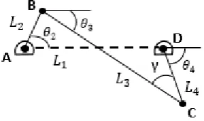
4.2.5. Four-bar Linkages Used in the Robotic Hand ... 55
4.3. Inverse Kinematics Techniques ... 57
4.3.1. Decoupling Technique ... 57
4.3.2. Iterative Technique ... 58
4.4. Combined Forward Kinematics ... 59
4.4.1. Angles of the Passive Joints ... 59
4.4.2. Further Kinematics. Transformations to the Fingertips. ... 69
4.5. Velocities and Accelerations ... 74
4.5.1. Velocities and Accelerations of the Passive Joints in the Palm ... 74
4.5.2. Thumb Velocities and Accelerations ... 76
4.6. Simulation Results ... 80
4.7. Summary ... 86
Chapter 5 ... 87
5.1. Introduction ... 87
5.2. Inertia ... 88
5.3. Recursive Newton-Euler Dynamics of the Robotic Hand Mechanism ... 89
5.3.1. Forces and moments in the fingers ... 90
5.3.2. Behavior of passive links ... 98
5.3.3. Calculations for torque 1 and 𝑭𝑩𝟎𝟏 ... 99
5.3.4. Calculations for torque 5 and 𝑭𝑩𝟒𝟎 ... 102
5.3.5. Simulation results ... 105
5.4. Summary ... 106
Chapter 6 ... 107
6.1. Introduction ... 107
6.2. Path Planning ... 107
3
6.4. Closed-Loop Feedback Control... 111
6.5. Summary ... 112
Chapter 7 ... 113
7.1. Introduction ... 113
7.2. Simulations ... 113
7.3. Summary ... 120
Chapter 8 ... 122
References ... 124
Appendix ... 129
The List of Figures
Figure 2.1. Commercial robotic hands for prosthetics and other uses ... 13Figure 2.2. Commercial robotic manipulators for industrial applications ... 13
Figure 2.3. Force capabilities of commercial hands ... 17
Figure 2.4. Mass of commercial hands in grams ... 18
Figure 2.5. Flexion speed of commercial hands... 19
Figure 2.6. Static limits of commercial hands ... 20
Figure 2.7. Actuation and flexibility of commercial hands ... 21
Figure 2.8. Prices of the commercial hands ... 22
Figure 2.9. Scientific robotic hands ... 24
Figure 2.10. Force capabilities of scientific hands ... 31
Figure 2.11. Mass of scientific hands ... 32
Figure 2.12. Actuation and flexibility of scientific hands ... 32
Figure 2.13. Prices of scientific hands ... 33
Figure 3.1. The principal dimensions. ... 36
Figure 3.2. Schematics of the palm. ... 37
Figure 3.3. Lower part of the palm, i.e. fixed link 5. ... 39
Figure 3.4. Double universal joint transmits the motion. ... 39
Figure 3.5. Structure of the finger. ... 40
Figure 3.6. Structure of the finger. ... 40
Figure 3.7. Thumb and lower area of the hand. ... 41
Figure 3.8. Four-bar mechanism of the thumb. ... 41
Figure 3.9. Holding a medium-sized ball. ... 43
Figure 3.10. Holding a medium-sized ball. ... 43
Figure 3.11. Holding a small ball. ... 43
Figure 3.12. Holding a small cube and a coin... 44
Figure 3.13. Holding a key. ... 44
Figure 3.14. Pencil handling 1. ... 45
Figure 3.15. Pencil handling 2. ... 45
Figure 3.16. Holding a bar. ... 46
Figure 3.17. Holding a mug 1. ... 46
4
Figure 4.1. Four-bar linkage (non-standard quadrants) 1... 56
Figure 4.2. Workspace of theta 3 joint (palm) in degrees. ... 80
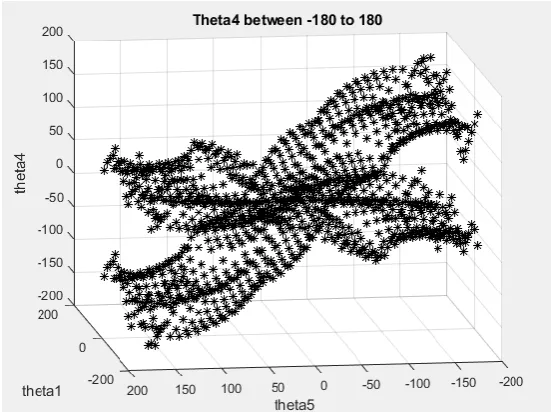
Figure 4.3. Workspace of theta 4 joint (palm) in degrees. ... 80
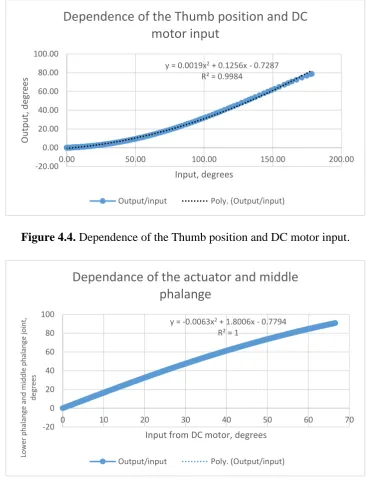
Figure 4.4. Dependence of the Thumb position and DC motor input. ... 81
Figure 4.5. Dependence of the actuator and middle phalange. ... 81
Figure 4.6. Dependence of the middle phalange and upper phalange joint. ... 82
Figure 4.7. Omega and Gamma dot relationship. ... 82
Figure 4.8. Relationship of Alpha2 and Gamma double dot ... 83
Figure 4.9. Ring and Middle fingers angular velocity ... 83
Figure 4.10. Index finger angular velocity ... 84
Figure 4.11. Thumb angular velocity ... 84
Figure 4.12. Thumb linear velocity ... 85
Figure 4.13. Index finger linear velocity ... 85
Figure 4.14. Ring and Middle fingers linear velocities ... 86
Figure 5.1. Centre of mass when fingers are flat ... 98
Figure 5.2. Centre of mass when index finger and thumb are bent ... 99
Figure 5.3. Load taken by palm’s DC motors ... 105
Figure 5.4. Load taken by fingers’ DC motors ... 106
Figure 6.1. Conditions for set motion ... 109
Figure 7.1. Finger is subjected to 10 N ... 114
Figure 7.2. Stress at lower joint during 10 N ... 115
Figure 7.3. 700 N.mm applied to the joint driven by outer linkage ... 115
Figure 7.4. Stressed outer linkage ... 116
Figure 7.5. Stress during 10 N application ... 117
Figure 7.6. Middle phalange and lower phalange joint ... 117
Figure 7.7. Outer linkage is stressed for perpendicular to the bottom joint 10 N at the fingertip .... 118
Figure 7.8. Failure of the outer linkage ... 119
Figure 7.9. 10 N are applied vertically to the thumb’s base ... 120
Figure 9.1. Fingertips can be tracked. Pink for thumb, green for index finger, blue and red for middle and ring fingers respectively ... 130
Figure 9.2. Theta 3 is 19.19 deg ... 130
Figure 9.3. Theta 3 is -21.34 deg ... 131
Figure 9.4. Only index is bent... 131
Figure 9.5. Only thumb is bent ... 132
The List of Schematics
Scheme 4.1. Position Transformation ... 50Scheme 4.2. DH approach58 ... 51
Scheme 4.3. Alternative coordinate system ... 52
Scheme 4.4. Twist motion (‘ri’ is vector ‘p’ in scheme 4.3)62... 52
Scheme 4.5. Four-bar linkage (standard quadrants) 1 ... 55
Scheme 4.6. Four-bar linkage (standard quadrants) 2 ... 55
Scheme 4.7. Four-bar linkage (non-standard quadrants) 2 ... 56
5
Scheme 4.9. Combined Kinematics ... 69
Scheme 5.1. Moment of Inertia of the cylinder71 ... 88
Scheme 5.2. Newton-Euler principle ... 89
Scheme 5.3. Upper part of the finger ... 91
Scheme 5.4. Upper phalange ... 91
Scheme 5.5. Middle phalange ... 92
Scheme 5.6. Driving link ... 93
Scheme 5.7. General case ... 94
Scheme 5.8. Lower phalange ... 94
Scheme 5.9. Special Case of the Lower Phalange. ... 95
Scheme 5.10. Special Case of the Lower Phalange. ... 96
Scheme 5.11. Situation in link h ... 97
Scheme 5.12. Situation in link p ... 97
Scheme 5.13. Free body diagram of the link 3 ... 100
Scheme 5.14. Free body diagram of the link 2 ... 101
Scheme 5.15. Free body diagram of the link 1 ... 102
Scheme 5.16. Free body diagram of the link 4 ... 103
6
DECLARATION OF ORGINALITY – CONDUCT OF
ASSESSED WORK
ASSESSED WORK WHICH DOES NOT HAVE THIS FORM ATTACHED WILL NOT BE ACCEPTED
Research Degree Programme……….
Assessment Title ………..…………..
Title of the report ………...
Family name of candidate ……….. (in BLOCK CAPITAL LETTERS)
Given name of candidate……….... (in BLOCK CAPITAL LETTERS)
ID number: ………
In presenting my Interim Assessment / Internal Evaluation (please delete as appropriate) I declare that I have read and understood the University Policy on Academic Misconduct
(available at http://www.salford.ac.uk/about-us/corporate-information/governance/policies-and-procedures/browse-by-theme/2) and that:
1. this work is my own
2. the work of others used in its completion has been duly acknowledged 3. I have been granted the appropriate level of ethical approval for my research
7
Acknowledgements
I would like to express my gratitude to my supervisor Dr. Guowu Wei for his patience and knowledge. I am very happy that I was able to get involved into challenging robotics theory
and improve my understanding of the field. Also, I would like to thank Catriona from postgraduate office for her support and understanding. My family was supporting me during
8
Abstract
This work presents analysis of the 4-fingered robotic hand and is a continuation of the Bachelor’s thesis “Design and Development of an Anthropomorphic Metamorphic Robotic Hand”. First, general comparison between scientific and commercial robotic hands is
introduced. Specification and structure of the hands are studied. Noted tendencies are discussed. After that, kinematic analysis of the proposed manipulator is produced. Based on kinematics, dynamic model of the hand is investigated and then programmed in MatLab software for numerical simulations. Therefore, description of capabilities and properties of the proposed robotic hand is given. In addition, control techniques are discussed and
9
Chapter 1
Introduction and Objectives
1.1. Introduction to Robotics
Science and engineering today make complicated designs possible and ideas from the past decades can eventually find realization. Manufacturing technologies continuously improve, allowing key parts to be transferred into small scale. Robotics industry will be one of the first to experience new capabilities.
In terms of robotic manipulators, when the first industrial robot was introduced by Dr. Engelberger1, manipulator patterns represented simple grippers with two or three elements to compress an object. In course of time, more demanding tasks to robotic hands were given. Then, anthropomorphism of the robotic hands has proven that the approach is viable and prospective if precision grasping of complicated objects is considered. Unlimited interest in anthropomorphic designs was then expressed and various prototypes were developed.
It is not only the industry that benefits from the advances in robotics sphere, but also medicine and prosthetics. Artificial body parts were developed even centuries ago, there are evidences that survived the time.2 It was important for people with lost limbs to look the same as others
– to feel themselves ‘complete’. Nothing has changed since then in terms of understanding completeness. Although ancient prostheses were rather cosmetic improvements than functional models, with higher level of technological progress it is now possible to almost fully retrieve natural limb functionality.3
While being an industry with a long historical background, robotics field gained significantly more attention in last few years, which resulted in increased funding and rapid growth of the sector. There are two main points of research interest – industrial robots and prosthetics. As the society tends to focus on automatizing most of the processes for both convenience and safety purposes, industrial robotic demand significantly increased. The International
10
by approximately 15% each year since 2017 and by 2020 is expected to be almost twice the number of robots supplied in 2016.4
As the competition increases, robotics industry attracts more scientist from various fields to improve the quality of the product, its functionality and safety of operation. Industrial robotics is focused on the simplification of production process, however, most of the robots still lack the artificial intelligence for complete autonomy and hence require the supervision of a professional to minimize the number of mistakes made during the manufacturing process. Therefore, robotics industry also attracts AI specialists, apart from material scientist, engineers and others, making it a high demanding interdisciplinary sector with plenty of development opportunities.
Another robotics discipline which deserved attention in last decades – is prosthetics. While attracting researchers from all physical disciplines, it is closely related to medicine and human psychology. If for industrial robots it is important mostly just to be able to functionate in a time- efficient and safe manner, usually regardless of size and complexity of the mechanism, then for prothesis requirements are stricter. Main points of concerns in prosthetics are the size and weight of the body part. Due to the size restrictions for customer satisfaction, production of a highly functional and sophisticated body part becomes a complicated process. Despite the market having a well-fitting to human needs prothesis for arms and legs, there is always more to be achieved with the development of medicine and physical sciences.
The minor part of robotics research is focused purely on producing functional stand-alone robots, with no direct relation to any of the discussed industries. For example, these can be surveillance, delivery, bomb disposal, rescue, animal-like or space robots. However, research in this field is vital too as it increases overall understanding of robotic systems and allows advanced methods to be employed in other sectors of robotics.
11
1.2. Objectives
This work presents the metamorphic anthropomorphic robotic hand, which utilizes the principles of gear transmission and actuator integration. In order to fully analyse its structure and performance, the following objectives were set:
• Produce the literature review and assess the common tendencies that are present on the market and in the research society.
• Provide detailed description of the robotic hand CAD model and discuss the features it has.
• Assess the kinematics and dynamics of the proposed design; develop and simulate the dynamic model.
• Describe the strategies of how the robotic hand may be controlled.
• Evaluate the weaknesses of the design and produce the FEA of vulnerable areas.
12
Chapter 2
Literature Review
In order to rightfully compare modern robotic hands and identify their unique design points, it is necessary to introduce two categories into which they will be split. Most of the robotic hands (quantity, not types) are made with ideas of high pragmatic approach – final product is based on profit and high production volume criteria. That said, durability and simplicity are main factors to be considered. Usually those hands have particular market and specific area of competence. Hence, they fit in commercial category. The other robotic hands, however, represent various prototypes to show maximum performance and abilities, broad potential and application, and, sometimes, just to acknowledge possibility of concept materialization. Those specimens are often made regardless of price matter, weight and aesthetics. Therefore, such robotic hands are closer related to scientific category. Scientific hands are a basement for the future commercial products.
2.1. Background of Commercial Hands
• Bebionic hands [A]
• Vincent Hand [D]
• The i-Limb hands [C]
• Michelangelo Hand [E]
• DLR hands [B]
• Body powered or electric fingers as partial hand options from Advanced Arm Dynamics [F, G]
• BarrettHand [H]
13
[image:14.595.122.496.85.360.2]Figure 2.1. Commercial robotic hands for prosthetics and other uses
Figure 2.2. Commercial robotic manipulators for industrial applications
2.1.1. The i-Limb hands
14
Bionics introduced the i-Limb pulse, the hand had more anatomically correct design,
improved durability and increased pulsing grip strength.8 Starting from the i-Limb pulse hand, patients could modify the hand via a special software. Over the next few years, company focused on improving the grip strength, durability and the shape of the prosthesis. The i-Limb quantum was launched in 2015 with a revolutionary simple control of the grips.8 The hand is easy to operate and modify for the patients (via mobile application) and also offers faster speed and longer battery life than previous Touch Bionics products.
2.1.2. Bebionic hands
First Bebionic hand by RSLSteeper was introduced in 2010. During the presentation of the hand in Leipzig, amputees had an opportunity to try the prosthesis in action. The appearance of the Bebionic hand is one of the key points that company focuses on as it makes patients more confident about their choice. In 2011, RSLSteeper launched Bebionic Hand v2, which came in large and medium sizes. It showed overall performance improvement, including speed, accuracy and durability. Significantly, several new grip patterns were added.9 New Bebionic3 was presented in 2012. It offered greater precision with faster speed and grasp strength. Bebionic3 comes with several wrist options, including multi-flex wrist that allows more natural wrist movement and positioning (up to 30°).10 This year (2017), Bebionic was
bought by Ottobock company and all further progression will be led by the new company.
2.1.3. Vincent Hand
Vincent Hand was first presented in 2010, at the same conference as Bebionic hand. It had the size and shape similar to the natural human hand. An option of production different hand sizes was also present without anatomical proprotions.5 The hand allows various types of basic grips: cylindrical, precision, lateral, hooking and key. There are, however, more options available for professional use.11 In 2014, Vincent Systems GmbH presented Vincentevolution 2 – first prosthetic hand with touch sensing.12 The hand allows amputee to feel the force feedback, which makes gripping much safer and natural. Vincentevolution 2 has anatomically correct size and shape of the hand, natural skin-like cover and ability to feel how strong one is holding an object.
2.1.4. Michelangelo Hand
15
just follow the driven ones. Thumb, however, can be moved separately and as a result, more hand positions are possible.13 The Michelangelo hand has a special, stretchable wrist joint (AxonWrist) that allows two possible modes: flexible and rigid. The flexible mode allows greater movement freedom and therefore provides the hand with an opportunity of more natural behavior.
2.1.5. DLR hands (Commercial)
DLR is a national aeronautic and space research center of Germany. Its division – Robotics and Mechatronics Center – is a competitive developer of various robotic hands. DLR Hand I – one of the first robot hand in which all the motors and electronics were housed within the space of the hand – was presented in 1997 and induced active research in integrated
mechatronics.14 DLR Hand II is an improved multisensory hand produced in 2001. Second DLR hand also has fully integrated actuators and electronic, but the shape of the hand was changed and amount of cabling was greatly reduced.14 Designed multisensory hand is mostly oriented on service use, such as teleoperation.15 The DLR Hand II is used on Rollin’ Justin – a humanoid robot for various service operations including both household use and assistance to astronauts.16
DLR Hand II application require high precision of finger position and applied force. Great control is achieved by utilizing multiple sensors, including three motors and three joint position sensors on each finger, three torque sensors and several temperature sensors. 17 Since actuators and electronics are integrated into the hand, it can be easily employed on various robots. Design of the hand allows fingers to be bend backwards, which provides more
16
With further development, DLR/HIT hand II was produced. It has five (instead of four) fingers with 3 DOF each (15 DOF in total). Despite having more fingers, hand is smaller and lighter than the previous version due to use of smaller and flatter motors and drivers.19 Second generation of the hand has become more human-like as the overall weight and size were reduced. An extra DOF from the thumb was removed, as it had no particular impact in the manipulation.19 The DLR/HIT hand II is used on humanoids for telemanipulation.20 This hand also gained iF Design Award in 2009.
2.1.6. BarrettHand
BarrettHand is a multi-fingered grasper that is used in multiple fields including component assembly, food industry, handling of various materials and others. The hand has enough dexterity to operate with objects of different shape, weight and size. Flexibility and high precision allows such applications as glass handling and even bomb disposal.21
2.1.7. Body powered or electric fingers as partial hand options from Advanced Arm
Dynamics
There are many partial hand options available from various manufacturers, including i-digits by Touch Bionics and VINCENTpartial. Advanced Arm Dynamics, is an American company that works with multiple prosthetic hand developers to supply amputees the prosthesis they require. One of the products is partial hand prosthesis that is designed for people who miss only some of the fingers. There are various options, including body powered and electric fingers.
17 2.1.8. Robotiq adaptive gripper hands (2-3 fingers)
Robotiq is Canadian company that focuses on production of service robots. Company produces two types of grippers: two-fingered and three-fingered. Two-fingered hand has several application fields, oriented on human-work replacement with automation. It is used for machine loading and unloading, automated assembly and in quality control.24 The gripper is reported to be simple in installation and control, ensuring compatibility with most of industrial robots.
The three-fingered hand gripper has similar application fields with an option of use in
[image:18.595.113.512.299.546.2]advanced manufacturing, as it is more dexterous and precise in comparison with two-fingered gripper. The hand is suitable for all industrial robots and is designed to pick object of any shape with maximum recommended payload of 10 kg.
Figure 2.3. Force capabilities of commercial hands
Unfortunately, not all the manufacturers provide the full force capabilities of their hands, however, it is still possible to compare some of them based on the information summarised on figure 2.3.
Among the prosthetic hands available for purchase, the Bebionic hand shows the greatest potential of providing enough grasp force for everyday life. It’s power grasp force is still dramatically lower than the potential grasp force of human hand, but not all of the grasp strength is used in everyday life, unless there are specific requirements for individual. Bebionic hand also provides reasonable palmer grasp force, but not the lateral grasp.
0 50 100 150 200 250 300 350 400 450 500 Bebionic hand
Bebionic v2 hand Michelangelo hand i-limb pulse hand* Vincent hand** DLR hand II DLR-HIT hand I DLR-HIT hand II Human native hand (men) Human native hand (women) Robotiq adaptive gripper hand (3 fingers) Barrett hand
Force / N
Force capabilities of commercial hands
18
The hardest point to achieve is the similar fingertip force as the human hand can provide. None of the commercially available prosthetic hands can provide sufficient fingertip force, which may make it harder for user to use their prothesis fingers to full extent.
The robotiq adaptive gripper hand is the only hand which provides similar fingertip force and hence can be effectively used in manufacture field or factories.
The lateral grasp can hardly be implemented by prosthetic hand. Michelangelo hand provides only half of the potential male human hand lateral grasp force, whereas the other hands cannot produce even a quarter of a human hand potential.
[image:19.595.130.496.343.564.2]Despite the force capabilities limitations of prosthetic hands, they still provide sufficient strength for most of everyday tasks and hence simplify life of injured individuals and increase the overall standard of living.
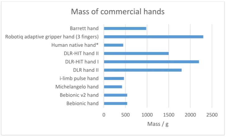
Figure 2.4. Mass of commercial hands in grams
Masses of commercially available hands are in reasonable range based on the areas of application. So the prosthetic hands are in a range of 460-550 grams, which is similar to the approximate average mass of human hand. Any other prosthetic hand, which is not included in the report, should also fall in the given range as it is the standard requirement for medicinal purposes.
The non-medicinal robotic hands are much heavier due to the requirements of the application field. So the Robotiq gripper hand, which is more likely to be used in factories, is the heaviest
0 500 1000 1500 2000 2500
Bebionic hand Bebionic v2 hand Michelangelo hand i-limb pulse hand DLR hand II DLR-HIT hand I DLR-HIT hand II Human native hand* Robotiq adaptive gripper hand (3 fingers) Barrett hand
Mass / g
19
of the listed hands: just above the 2.25 kg. The second heaviest hand is DLR-HIT hand, which reduced the size and mass in the second generation.
[image:20.595.130.495.175.404.2]The weight of the commercially available hands differs dramatically based on application, however, the mass of the particular hand is always likely to be in an acceptable range for the robot utilisation field.
Figure 2.5. Flexion speed of commercial hands
Another point of comparison robotic hands is the flexion speed they provide. Based on the figure 2.5, the main drawback of the commercially available prosthetic hand can be identified to be the flexion speed. The second generation of Bebionic hand provides the fastest flexion speed of all the prosthetic hands, however, it is still less than ¼ of the human hand capability. The lack of flexion speed affects person performance in emergency situations, such as
inability of catching the falling object. This is the common situation in everyday life and hence the small flexion speed will affect the performance of disabled person quite
dramatically. However, apart from the unexpected situations of objects falling, the flexion speed is acceptable in most of the activities. The process of flexion is still much slower than for human hand, but the ability to do so already improves the quality of life of disabled person.
Other robotic hands, such as second generation of DLR hands and Barret hand, provide a comparable flexion speed to human hand potential. The Robotiq gripper hand, which was leading in previous points of comparison, has flexion speed similar to prosthetic hands. But in
0 100 200 300 400 500
Bebionic hand Bebionic v2 hand Michelangelo hand i-limb pulse hand Vincent hand DLR hand II DLR-HIT hand I DLR-HIT hand II Human native hand* Robotiq adaptive gripper hand (3 fingers)* Barrett hand
Flexion speed / deg/sec
20
case of the gripper, the precision and strength of grip are more important than the speed of flexion.
Figure 2.6. Static limits of commercial hands
Static limits are rarely provided by the manufacturer; however, it is an important parameter, especially for the prosthetic hands. Based on figure 2.6, it can be concluded that i-limb ultra prosthetic hand, greatly outstrip the Bebionic hand. This may be an advantage for individual who requires a high load limit to be present. On the other hand, the hand load limit of approximately 45 kg in Bebionic hand, should be sufficient for most of the everyday
activities. Considering other advantages of Bebionic hand listed above, it may still show the great performance in heavy loading.
The finger carry load is nearly similar for both of the available prosthetic hand, with i-limb ultra being about 10 kg further.
The non-prosthetic robotic hands have much lower static limits, which seriously affects the range of fields where these hands can successfully be used.
0 20 40 60 80 100
Bebionic hand i-limb ultra
Robotiq adaptive gripper hand (3…
Barrett hand
Static limit / kg
Static limits of some commercial hands
21
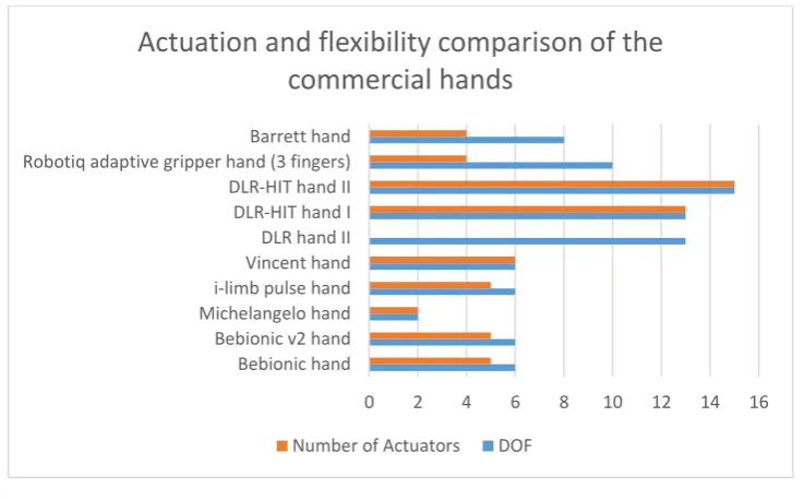
Figure 2.7. Actuation and flexibility of commercial hands
As shown on figure 2.7, commercially available hands are either underactuated or fully actuated. Most of the prosthetic hands are underactuated, which slightly affects the ability of the hand to follow the commanded arbitrary trajectory. The fewer number of actuators, however, reduces the weight of the prothesis, which is more desirable than exceptionally accurate motion control for everyday use. The number of degrees of freedom (DOF) is similar for most of the prosthetic hand, which is expected as it should obey the human hand
characteristics.
The DLR hands have much larger number of DOFs and are fully actuated, therefore, they are much more precise in motion. This also explains the large mass (up to 2.25 kg) of the
prototype and provides an idea of why there cannot be many actuators in prosthetic hands at this stage of the robotics field development.
0 2 4 6 8 10 12 14 16
Bebionic hand Bebionic v2 hand Michelangelo hand i-limb pulse hand Vincent hand DLR hand II DLR-HIT hand I DLR-HIT hand II Robotiq adaptive gripper hand (3 fingers) Barrett hand
Actuation and flexibility comparison of the
commercial hands
22
Figure 2.8. Prices of the commercial hands
The final point of comparison is the price of the discussed hands. As expected, the range of prices is huge due to the various reasons including the materials used, performance
characteristics and application field.
Prosthetic hands prices differ mostly based on similarity of visual appearance of the prothesis to human hand: the more alike the prothesis is, the higher the price. Due to the human nature, individual is more likely to prefer the weaker hand but which looks similar to the natural hand, rather than a high-performance but dissimilar to human hand prothesis.
The non-prosthetic hands also differ in price, mostly based on the performance characteristic: the more efficient hand is, the higher the price. Therefore, DLR hand is much more expensive than Robotiq gripper or Barrett Hand.
*Although the Deka Arm (‘Luke Arm’) is a system that includes more parts than just a hand (literature review aims to observe hands, not arms), it is still considered for the reference purposes. Deka arm was a scientific project and only recently in 2014 was approved by FDA (U.S. Food & Drug Administration)25, making it commercial product. It is important to note that mentioned price is set for the product which has the latest technologies integrated and allows user to have sensitive feedback. It also supports targeted muscle reinnervation (TMR)26 that vastly enhances control of the arm.
2.1.9. Comments
Prosthetic robotic hands that are currently present on the market tend to have a rigid palm structure to store actuators. Their number of DOF is optimised in the way that the size of the
0 20000 40000 60000 80000 100000 Bebionic hand first generation
i-limb hand first generation Bebionic3 hand Michelangelo hand
i-limb ultra DLR-HIT hand I Deka 'The Luke' arm* Robotiq adaptive gripper hand (3 fingers) BarrettHand
Price comparison of the commercial hands
23
hand would be human-like, but at the same time providing considerable force and grasp variety for daily operations. In addition, excessive number of actuators leads to increased weight of the prosthesis, extra power requirement (battery), enlarged proportions and less acceptable shape. Distinctive characteristics dramatically influence production costs and final price of the product.
As for industrial applications, anthropomorphism is not required for basic manipulations with objects, so therefore grippers are mostly used as an inexpensive and reliable solution.
2.2. Review of Scientific Robotic Hands
• Biomimetic anthropomorphic hand by Zhe Xu and Emanuel Todorov [A]
• DLR hands [David’s Hand – B]
• Elu-2 Hand [C]
• KCL 3-finger metahand [D]
• Modular soft robotic gripper [E]
• RBO Hand 2 [F]
• Multifingered metamorphic hand by G. Wei et. al. (has options of 4 or 5 fingers) [G]
• The Robonaut Hand [H]
• UB Hand I-IV [I]
• The SmartHand [J]
24
Figure 2.9. Scientific robotic hands
2.2.1. Biomimetic anthropomorphic hand by Zhe Xu and Emanuel Todorov27
The idea of this hand strongly relies on the desire of many engineers to replicate human natural hand. Introduced on the 18th of February 201628, the robotic hand represents an outcome of the mentioned aim and elastic materials. Its structure includes tendon-based actuation with cooperation of unique and novel parts like elastic pulley mechanisms, laser-cut extensor hood, artificial joint capsules and crocheted ligaments. In terms of bones re-creation, laser/MRI scanner was used to carefully capture shape of bones. In order to prevent abnormal sideways bending of each joint of the hand, artificial ligaments as strong fibrous tissues are applied. Also, index finger, as well as middle finger and thumb, is actuated with more than two servo motors ensuring extra control. Human hand similarity ensures high number of DOF (Degrees of Freedom).
25
manipulations with objects, grasps; and overall it is an important contribution to the prosthetic science. As for minor drawbacks, servo motors are housed outside the hand, so that additional space for the actuation system is required. Also, tendon-based systems are known for the relative durability.
It would be important to point out that this hand is a working prototype that shows possibility of the concept, so further development will take place.
2.2.2. DLR “David’s” Hand
DLR hands were discussed in details in commercial hands section. However, DLR has produced an unusual robot hand that is not available commercially. The David’s Hand is the same size and shape as human hand. The hand has five separately movable fingers with each joint being actuated with two motors.29 Fingers are controlled with 38 tendons, which results in 19 DOF. Flexion speed of each joint is described as 720 deg/sec.Apart from structure similarity, hand was designed to function as a natural hand: to withstand collisions with heavy objects without breaking.30 High durability is achieved because of the controllable stiffness due to the produced tension in tendons. Therefore, David’s hand can endure large impacts. The hand utilizes strong Dyneema tendons.29 The production of such durable hand can reduce
the risks of significant damage dealt to the robotic hand during its application in real world. The David’s hand is part of DLR Arm System, which is presented in form of David – robot developed in 2010 in order to achieve more human-like dexterity, dynamics and robustness.31
2.2.3. Elu-2 Hand
Elu-2 Hand is a multi-articulated robotic hand produced by Elumotion Ltd. The hand has five fingers with 9 DOF. It was designed to produce movements at human-like speed and therefore may easily interact with people and various tools and object in the environment.32 Elu-2 Hand is also known as Servo-electric 5-Finger Gripping Hand SVH and is distributed by SCHUNK. The hand comes in left- and right-handed versions, both of which can be fitted to most of light industrial robots.33
2.2.4. KCL 3-finger metahand
26
which orientation is dependent on the palm’s motion.36 The foldable hand adapts to various
shapes of the object and hence has wide range of possible applications.
2.2.5. Modular soft robotic gripper37
Soft robotics is entirely new approach in robotics and it is a totally new direction in the history. There are not yet many systems engineered using this technology, but the modular soft robotic gripper is one of them. It was introduced in a scientific paper in 2015. Main contrast and advantage of the soft robotics compared to solid designs lies in the pursue of many scientists to obtain perfect compliance of their robotic mechanisms. Main industrial solutions represent designs like already mentioned BarettHand and Robotiq grippers with corresponding limitations. Aim of the modular soft robotic gripper is to successfully grasp objects of the unknown shape. Gripper’s specifics allows interaction with very fragile, delicate objects. Therefore, this area of research is remarkably, supremely advanced and prospective. As a general downside of the soft manipulators, it is pointed out that due to extra compliance it would be problematic to predict particular pose of the soft gripper or hand, although very likely to obtain object’s shape. The study was manly focused on enveloping and pinch grasps.
Presented soft robotic gripper is underactuated with pneumatics. It is currently made with main idea to be attachable to fingers of the solid hands or manipulators. Presented work outlines serious superiority over solid manipulators in terms of grasp tenderness.
Drawbacks evaluated during the study list sensor readings being unacceptably noisy. Further research will also involve additional attention to sensorial classification of the objects for better grasp accuracy. In addition, slippery and heavy objects do represent certain level of problem and should face an engineering solution in the future.
2.2.6. RBO Hand 238,39
While some soft robotic systems are tested and addressed more for industrial use, meanwhile there are interesting examples of anthropomorphic soft robotic designs intended for future prosthetic use. RBO Hand 2 is one of them. It was fully described in 2015.
27
handling load more than 0.5 kg with certain adjustments, while being able to produce 31 grasping motions described in Feix grasp hierarchy. Obvious disadvantage of the soft robotic designs is restriction from the interaction with sharp objects that can damage the hand. But due to seriously decreased cost price, it may not be classified as a defect of the design. Moreover, such hands could be used under hazardous conditions, because the overall risk does not involve loads of money.
As to grasping capabilities, it was detected that distal type grasp and light tool grasp of scissors and pencil respectively cause problems. But these are minor fails for the first prototypes in this area. Hand is able to apply 6-8 N forces and that is enough for most of the daily objects. A harder rubber is suggested for making higher forces involved in grasping operations. Also, slippery problems that were already discussed in a different section are present here as well. All in all, for a hand worth only 77 pounds – presented efficiency is for sure a breakthrough in financially optimal robotic anthropomorphic designs.
2.2.7. Multifingered metamorphic hand by G. Wei et. al.40
The best example of the practical application of the metamorphic hand developed by G. Wei et.al. could be considered the DEXDEB project. The successful prototype was tested in serious environment alongside with the Shadow Hand.
The four-fingered metamorphic hand has 15 DOF overall, its palm is formed by five-bar linkage based on spherical principles. Since the hand is metamorphic and highly flexible, for simplification, weight reduction and contradiction prevention underactuated tendon-based external actuation is integrated. Each finger is actuated by two motors, making overall actuator number of 10, including two actuators for the palm.
Deboning research has evaluated that occurring friction and wear of the tendons should be carefully studied further. Recommendation for the metamorphic hand weight reduction was made.
In general, outstanding results of the metamorphic hand were presented and it is possible to predict demand in designs based on the metamorphic principles in the nearest future.
2.2.8. The Robonaut Hands41,42
28
Also, specific conditions of working area should be mentioned – all electronics and actuators have to be perfectly sealed and pressurized in order to work in vacuum. The robonaut hand (as part of the proper robot) is designed to reduce (or to completely replace) human presence outside a space station. Back then it was the most advanced hand engineered for space considering several other hands under development and even some grippers already tested in space conditions. To list some of the stated requirements: force of 88.9 N and torque of 3.39 N.m should be achievable (for the whole arm module). Variety of grasps is dictated by necessary compatibility with EVA (extra-vehicular activity) interfaces at International Space Station. Strict restrictions are applied to materials and motors: extreme temperature level change withstanding ability, contamination prevention standard fulfilment, lubrication certified for space use, etc. Overall DOF number of the hand is fourteen, including 2-DOF wrist. The forearm is carrying all fourteen motors with necessary electronics and is of 10.16 cm by 20.32 cm size. Leaving hand empty of actuators is justified by limitations applied to its required overall size. As a more reliable and durable competitor than tendon actuation, flex shafts are used. Leadscrews attached to the fingers provide final linear motion. For
outstanding control, more than 43 sensors are used. Each finger has not common extra durable 7-bar linkage system and there are special elements integrated in the fingers and hand that reduce backlash and vibration. Since this robotic piece of art was first in class, only the following minor disadvantages could be mentioned: most of the parts have complicated geometry, leadscrew actuation is done only one way in order to save the tool in the power loss scenario – otherwise extra forces required for finger back extension will overheat the motor and damage it.
Second generation of the robonaut hand, The Robonaut 2 Hand, introduced in 2011 is expected to have serious advantages over its previous generation. Major differences involve increased DOF number of the thumb for better grasping at certain positions and improved reachability, overall durability increase and optimization where possible. Number of
conductors was decreased from 80 to just 6, meaning better utilization of the limited space. In addition, while hand module above forearm is now designed to easily be taken off, the
29
by five. Remaining fingers are underactuated. It is important to note that now design has polymer tendon system for better finger shape optimization and simplification purposes. Special ‘Vectran’ material is used for tendons; its breaking force is 1775.61 N at diameter of 1.2 mm. Each actuator is able to provide pull force of 225.63 N. But now due to tendon system the hand is compliant, so therefore there is a risk of losing a tool in space. As a solution and substitution of the leadscrew technology, gloves of whether low or high flexion friction are now used. This means that in case of the emergency, fingers will not extend back due to high friction. They will only be able to do so when additional torque overcoming the friction will be applied.
It is concluded by researchers that ‘Spectra’ polymer material for tendons is better for abrasion resistance and durability properties than ‘Vectra’ material, but the latest is chosen only because of the limited compatibility. It is also highlighted that abrasion prevention is improved with Dupont Krytox lubricant for tendons and leaded phosphor bronze as finger material. New tendon material and overall actuation system design allowed increased level of break strength overall durability with considerable factor of safety. Elastic actuation is
recognized as a positive innovation and further development will continue to replace solid parts where it is rightly.
2.2.9. UB Hand IV
30 2.2.10. The SmartHand44
The SmartHand is a prosthetic hand developed by Scuola Superiore Sant'Anna (SSSA, University in Pisa, Italy). The hand has five underactuated fingers, 16 DOF and 40 different sensors. Hand is actuated only by 4 motors and is bent with single tendon.45 Only thumb and index finger are separately actuated, whereas middle to little finger are actuated with one DC-motor. The last actuator is used for thumb abduction/adduction.45 Moderate flexion speed is assured: 90 deg/sec. Such design does not allow complicated grips and movement, although power, precision and lateral grasps are possible along with pointing and counting. The aim of the SmartHand, however, was just to make possible basic everyday gestures, which was achieved with weight and speed characteristics comparable to that in commercial prostheses.45
2.2.11. The Shadow Hand46,47,48,49
Another example of solid design that is close to human hand functionality is the Shadow Hand. Initially, its prototype was presented in 2002 in Japan. The first commercial version with pneumatic muscles was introduced in 2004, but in 2008 option with electric motors became available. One of the aims of the whole project was to investigate and develop advanced tactile sensors. In general, the hand is intended to serve as a test system for intelligent manipulation and grasping. Therefore, it is not designed for non-professional public, but rather for research institutions. Prototype that could be bought and tested by various research groups.
Research on tactile sensing has led to the shadow hand’s most unique selling point – it was equipped with special novel sensor placed on the fingertip that has 34 tactile regions and is vulnerable even to 3g of applied weight. Other advantages are also mentioned: fast
construction time, high compliance (which back then was not very common) for interaction with humans, outstanding dexterity and significant maneuverability ensured by 25 DOF producing 24 different movements. The fact that the hand became a product out of the
prototype means that it was a serious contribution to the overall robotics field and particularly general purpose robotics. One of the research groups have tested and positively identified hand’s functionality50.
31
Furthermore, the hand has been involved in neural control, industrial quality control and brain computer interface research.
Figure 2.10. Force capabilities of scientific hands
Unfortunately, only few force parameters are provided by scientists on their hands. The main point of interest is therefore the fingertip force and the power grasp. DLR hand provides twice higher fingertip force when Dyneema fiber is used instead of steel tendons. The robonaut hand uses the polymer tendons and provide just a bit higher fingertip force than DLR hand with steel tendons.
The power grasp information is provided only for three scientific hands, with the first generation robonaut hand unquestioningly leading. It may be assumed that the second generation robonaut hand should have similar properties, as the force capability tends to improve in every next version of the hand, both commercial and scientific.
0 20 40 60 80 100
DLR, David's hand with steel tendons DLR, David's hand with Dyneema RBO hand 2 The robonaut hand The robonaut hand 2 The SmartHand
Force capability / N
Force capabilities of scientific hands
32
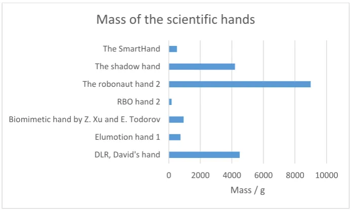
Figure 2.11. Mass of scientific hands
[image:33.595.138.486.54.266.2]Scientific hands are much heavier than commercial hands, as they do not require the similarity to human hand and only focus on the precision and performance efficiency. The mass of the hand mostly is affected by number of actuators, materials and size of the hand. The mass range is clearly visible on figure 2.11 and does not require any further explanation.
Figure 2.12. Actuation and flexibility of scientific hands
As expected from scientific hands, were the accuracy and control of movements is usually the most desirable parameter, most of the hands are overactuated. There are, however, plenty of examples of underactuated (RBO hand 2, Elu hand, The SmartHand) and fully actuated hands. Due to the nature of scientific research, all three types of robotic hands must be studied in order for robotic field to develop further.
0 2000 4000 6000 8000 10000 DLR, David's hand
Elumotion hand 1 Biomimetic hand by Z. Xu and E. Todorov RBO hand 2 The robonaut hand 2 The shadow hand The SmartHand
Mass / g
Mass of the scientific hands
0 10 20 30 40 50
DLR, David's hand Elu hand 2 RBO hand 2* Four-fingered meta. Hand by G. Wei The robonaut hand The robonaut hand 2 The shadow hand, model c6 The shadow hand, model c6m The SmartHand
Actuation methods implied and flexibility
33
Figure 2.13. Prices of scientific hands
Not many of scientific hands are available for purchase as it is usually the only exemplar and is only studied within particular research group. The hands that are available, however, are mostly expensive. The price depends on the performance, material and size of the hand, similar to commercial robotic hands. The RBO hand 2 is being the most cost-effective due to the lack of efficiency in comparison to other hands described above.
2.2.12. Comments
Scientific hands are mostly task-specific rather than commercial general-purpose hands. Hence, desired performance is obtained regardless of price, weight, dimensions, etc. Improvements that were made by scientific hands, problem solution ideas and a novel approach lead to better commercial products in the future. It was also noted that scientific hands typically represent prototypes and are rarely produced with quantities higher than 1. However, developers of the Shadow Hand have made their product available for research groups and universities, but the public access is highly limited due to the price, which is only affordable by large organizations/corporations.
2.3. Summary
The commercially available hands have been compared purpose-wise and reasonable price to quality ratio was observed. Unfortunately, not all the manufacturers provide full
characteristics of their product and not all of commercially available hand could be discussed. More detailed research and comparison of commercial hands characteristics may be
performed in future work.
0 50000 100000 150000 200000
DLR, David's hand Elu hand 2 RBO hand 2 The shadow hand
Price comparison of the scientific hands
34
There exist a huge number of scientific robotic hands as this is the main research ground for all further development of commercial products. With the range of hands with different properties including type of actuation, material of tendons or other driving mechanism presence, robotic hand scientific research remains the main drive for robotic industry development.
35
Chapter 3
Robotic Hand Design
3.1 Introduction
Design is an irreplaceable part of engineering project. It is a complex process which combines certain sequence of tasks, where some parts are constantly repeated for design improvement purposes. Design is a fundamental part of engineering, without which accomplishment of required task could not be achieved. The final result of design is a set of specifications from which the final product can be built.51
Design is a process in which variety of factors must be considered: environment in which the final product will operate, existing standards and requirements for the designed product, target audience, etc. Therefore, the purpose of the designing process is to find the optimal
interception between the physical properties, environment requirements and ease of
application.52 Design complexity is also affected by the fact if the product is modernised or invented at first place. However, regardless of the initial task, design procedure can be divided into several parts to simplify the task.
Mechanical design involves variety of mathematical calculations prior to the production of the designed product. As obtained results can prove design mistakes, changes to specifications are made constantly throughout the design period and after the first tests of the built product.52 In help comes programming software, which simplifies introduction of changes to the final results. Most of the design engineering software nowadays are connected between each other so that the designer can interconvert new mathematical calculations to the change of
specifications in a least time-consuming way.
36
product with both efficiency in terms of fulfilling the required function and at the same time cost reasonable of money to produce for the company to make profit in long-term perspective. Design is not purely technical and scientific process, as creativity of designer and their ability to gather and separate certain information about the final product simplify the core of all the design projects – identification of the need. Design is an iterative process, where at every step new information about the product is gained and hence the design may change. Some of the issues might be found at the mathematical calculation stage, some at simulation stage and some can only be identified when the product is built. It is vital to understand that mechanical design, in particular, combines all mechanical engineering disciplines, and therefore requires the designer to have certain level of engineering literacy.
This chapter gives a description of what is the mechanism behind the achievement of various hand postures. Design complexity and possible areas of manipulator application are
discussed. Furthermore, grasping of different shape objects is introduced to demonstrate capabilities and evaluate downsides of the design. Conclusions of this chapter will make a ground to the overall structure simplification and future work.
3.2 Design Overview
37
Figure 3.2. Schematics of the palm.
In general, structure of the mechanism can be split into several sections (figure 3.2):
➢ The supporting unit that is meant to be attached to the robotic arm. The unit is carrying the robotic hand and wrist actuator.
➢ The lower section of the palm (link 5), which stores its two actuators. As the whole palm spherical mechanism has only 2 DOF, the other links have only actuators for the fingers.
➢ The upper section of the palm (link 4), which is carrying the middle and the ring fingers, as well as their DC motors. It is actuated with a DC motor.
➢ The ring finger’s palm section (link 3), which is a passive link, containing a DC motor.
➢ The thumb’s palm section (link 2) – passive link with a DC motor inside.
➢ The small crank (link 1), which is actuated through a double universal joint.
➢ Individual fingers. Index, middle and ring fingers have a similar structure. Thumb’s lower part has a unique design due to the four-bar actuation mechanism.
Principal dimensions make it possible to compare this anthropomorphic manipulator with the human hand. Of course, the idea of implementing actuators inside the palm is not novel – it is found in most of the commercial prosthetic hands with rigid palm. However, the same
38
As it is seen on the figure 3.1., the overall height of the robotic hand with its attachment module is 326.15 mm. Thickness is 24 mm maximum, excluding the attachment module. Length of the 3 phalanges is 112.29 mm, increasing to 175.78 mm with the DC motor and gearbox. Inner breadth is 60 mm.
According to the anthropometric survey53, length of the natural hand varies from 158.9 mm to 205.0 mm and from 172.8 mm to 219.0 mm for women and men respectively. Hand’s breadth differs from 80.7 mm to 100.4 mm for men, but for women is about 10 mm less on average. Hence, it is not likely that the proposed manipulator would be able to fit into the commercial prosthetics category. Although addition of the fifth finger would make the manipulator more attractive, the robotic hand is still beyond the expected dimensions for prosthetics.
Nevertheless, it can be suitable for minority of people that prefer to show to the public that they have an artificial and non-standard limb. In this case, larger proportions of the robotic hand outline its uniqueness. As for the industrial applications like meat deboning40, developed manipulator would perfectly fit – the gear transmission is superior than the tendon principle in terms of accuracy and durability, while oversized and irregular shape does not have a
significant impact on the operation and task fulfilment.
The tendon principle requires actuators to be stored outside of the manipulator – this factor greatly optimizes the shape and proportions, but meanwhile complex mechanisms with many DOFs will have all actuators stored inside the forearm. This may not be convenient in cases when the forearm is required to be small or available space is mostly occupied by other electronics like sensors and controllers.
Since the proposed robotic hand has only 4 fingers, it is important to understand how
39
Figure 3.3. Lower part of the palm, i.e. fixed link 5.
Figure 3.4. Double universal joint transmits the motion.
The palm, which is represented by the five-bar spherical linkage, can be controlled by 2 DC motors. In order to have as much unconstrained motion of linkages as possible, the inner area of the palm is left empty. Hence, space limitations obliged one of the palm’s DC motors to transfer its motion through 2 universal joints. The total angle of motion transfer is 156 degrees. The bearings are securely blocked with the highlighted retaining rings. The lower section of the palm, link 5, has circular cavities for DC motors to be fitted in. It can also be seen on the figures 3.3 and 3.4 that the attachments to the palm provide fixation of actuators and cover from external interferences. The ones that have to hold an actuator are meant to be made out of aluminium or steel, whereas the others that act as a cover are intended to be made out of plastics to avoid manufacturing complications (difficult to reproduce shape) and not necessary weight.
40
humans, – it has some compliance. When impact takes place, linkages that connect linear actuators with fingers are folding and therefore allow fingers to freely move backwards to certain extent. This is something to think about if the proposed manipulator would be required to be adapted for prosthetics applications.
Steel bevel gears that are used in the palm and fingers have a 10.7 mm diameter and offer 1:1 transmission. Although the overall size and teeth dimensions are modest, nevertheless, the gears are capable of withstanding torque up to the 3.9 N.m according to their specification. Higher transmission ratio to increase the torque is not available due to strict space limitations.
Figure 3.5. Structure of the finger.
Figure 3.6. Structure of the finger.
41
additional material support from the side walls in order to reduce the load from the screws when decompression takes place.
Figures 3.5 and 3.6 help to understand how the finger was assembled. It can be seen that the bearings are covered only for four joints. Circular protrusions of the middle phalange in the lower section act as shafts. Other parts that are placed on shafts have set screws where possible to provide additional fixation. The role of the small DC motor is to force the middle and the upper phalanges to acquire certain posture, before the final torque from the finger's main actuator (which is located inside the palm’s link for each finger) is applied. In terms of joints, rivet joints may be suggested as a cost-effective alternative, if the maintenance is not expected in the nearest future of manipulator service. This is also a way how to reduce manufacturing complexity of the middle phalange.
Figure 3.7. Thumb and lower area of the hand.
Figure 3.8. Four-bar mechanism of the thumb.
42
Four-bar mechanism is used inside all fingers and is also actuating the thumb. It was already proven by Bebiobic Hand that this principle is efficient, convenient and reliable way of
motion transfer. Belt transmission would have been harder to implement when available space is very limited. Especially with the fact that belts are installed on pulleys. However, it may be considered as an option inside the arm as gears are more expensive.
Specifications of DC motors:
• DC motors inside the finger: Faulhaber 1512_012 SR, reduction 324:1, max. 50 mNm.
• DC motors in the palm links: Maxon EC 20 flat A (351100) with planetary gearhead GP 22 C (143989), reduction 157:1, max. 1.9 N.m.
• Servo motor is included for reference purposes. It can be of any size, depending on the application and size affordability of the attachment module. CAD model is based on the Hitec servo motors.
3.3 Grasping Capabilities
Object grasping is the most important test of the anthropomorphic manipulator. It is the easiest way to assess if the proposed robotic hand has enough performance to meet the requirements. This process outlines design flaws that have to be eliminated and advantages that should be advertised.
43
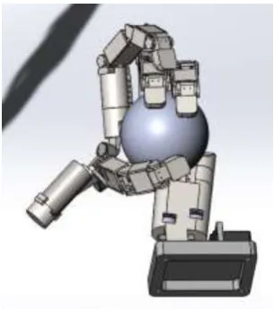
Figure 3.9. Holding a medium-sized ball.
[image:44.595.235.388.246.419.2]Figure 3.10. Holding a medium-sized ball.
Figure 3.11. Holding a small ball.
44
the possibility of providing at least three contact points. Popular commercial hands have a special movable platform for the thumb in order to provide various hand posture support. However, the metamorphic anthropomorphic robotic hand is capable of rotating the basement of index finger in addition to the thumb’s. Moreover, with only 1 DOF in commercial hands, the fingers are forced to bend all three phalanges altogether. 2 DOFs of the proposed
manipulator give extra workspace and posture variety.
Figure 3.12. Holding a small cube and a coin.
Figure 3.13. Holding a key.
45
Figure 3.14. Pencil handling 1.
Figure 3.15. Pencil handling 2.
Since the advancement of technology, with the invention of computers, the habits of humans have changed. A large amount of time is now spent using hand-held portable devices, such as: laptops, mobile phones and tablets. Hands and fingertips are required to adapt to the new circumstances - to grasp and grip smaller objects.
Pencils (figures 3.14 and 3.15) and pens used to be objects with higher frequency of utilization in comparison to any others. Nowadays all documents are maintained
46
Figure 3.16. Holding a bar.
A bar is often encountered in buses and stairs. The same closure pattern is applied to any bags that should be carried. As seen from the figure 3.16, the robotic hand is able to successfully hold a bar.
Figure 3.17. Holding a mug 1.
Figure 3.18. Holding a mug 2.
47
obliged to maneuver the mechanical links around the handle to grip and lift the mug. It can be observed on the figures 3.17 and 3.18 that thumb also plays a key role in securing the stable grasp. Thumb prevents the mug from deviating down. Ring finger can be used as an
additional support underneath the mug.
Another aspect of the object manipulation is friction. It is necessary to note that the steel or aluminium materials on their own are not improving grasping. There are situations when slippery objects should be handled. Absence of high friction does not affect the function, but it might influence the performance. There are a lot of cover materials with high friction coefficient that can be (or should be if there is such demand) applied to the fingertips and other parts, so therefore it is inconsequential to address it in more detail.
f
3.4 Summary
Overall, design is a complex interdisciplinary part of engineering, which is mainly based on decision-making. Then, the decisions are modified with every new information obtained in order to optimize the final product. There is no completely final point of the design as it is extremely flexible and hence, should be easily adjustable for further needs of the research or consumer. Design starts with a specific idea and set of requirements that can be achieved in a variety of ways, which are only limited by the chosen approach. And this is what makes design a fundamental unit of the progress.
Although the developed robotic hand might be of a limited value to prosthetics, there is a limitless demand in the industrial applications. Provided evidence of the robotic hand’s grasp potential shows that the manipulator is capable of being used in operations involving objects of intricate shapes or procedures that require complex postures.
48
Chapter 4
Kinematics
4.1. Introduction
Forward kinematics represents a set of transformation matrices that leads to the end effector of manipulator. Obtained result shows position and orientation of the end effector.55, 56 Inverse kinematics is a mathematical technique which finds the joint properties based on the desired end-effector (or fingertip) position. The IK approach is rather complicated as there exist various joint position combinations at which desired fingertip position is achieved. The presence of more than one suitable combinations comes from the fact that transformation matrix (0T
n) is composed from trigonometric functions of joint variables.5 Which by
definition have infinite number of solutions. In order to suit a particular case, several
analytical and numerical methods for solving inverse kinematics problems are known. These include such approaches as decoupling technique, inverse transformation technique and iterative method.
In this chapter, method of obtaining kinematics equations is described.
Although sections containing equations of accelerations are mostly reviewed in dynamics chapter of books, for convenience purposes and better information representation, they will remain in kinematics chapter.
4.2. Preliminary Theory
4.2.1. Orientation and Translation. Position in Space57
Before the kinematics can be considered, it is necessary to define a coordinate system to show the way how results will be presented. Although there are various options available, in this work, everything is based on the Cartesian coordinate system.