2017 3rd International Conference on Electronic Information Technology and Intellectualization (ICEITI 2017) ISBN: 978-1-60595-512-4
Voltage Flicker Analysis Based on Improved
Independent Component Analysis
Yanfei Jia, Xin Wang and Xiaodong Yang
ABSTRACT
The traditional independent component analysis uses Newton method to optimize its cost function, so it always falls into local optimal solution. This affects its application in voltage flicker detection. To improve the performance of voltage flicker detection based on independent component analysis, this paper uses artificial bee colony algorithm that has global optimization to optimize the cost function of independent component analysis. Simulations prove that the improved voltage flicker detection method has better performance than the original method.
INTRODUCTION
Voltage flicker refers to voltage magnitude fluctuations, which are an important concern in power quality. With increasing nonlinear volatility and impact load in a power system, voltage flicker becomes increasingly serious, and can cause damage to electrical equipment and production loss. Many techniques have been suggested for digital analysis of voltage flicker. Until now, the algorithm based on Kalman filter has been effective, which uses a linear Kalman filter to estimate instantaneous fundamental voltage, but its calculations are complicated [1]. Fast Fourier transform (FFT) effectively measures flicker voltage magnitude and frequency [2]. The leakage effect is a major error associated with FFT applications. The application of continuous wavelet transforms and S-transforms for voltage flicker detection can ________________________
Yanfei Jia. College of Electrical and Information, Beihua University, Jilin, China
Xin Wang. Grid Information & Telecommunication Group, Beijing China Power Information Technology Co. Ltd., Beijing, China
overcome most disadvantages of FFT [3]. However, the wavelet function is not unique, so the choice of an applicable function is difficult.
Traditional independent component analysis (ICA) method has been applied to deal with voltage flicker [4-5]. However, the traditional ICA uses Newton iterative method to optimize the cost function. It is easy to jump into local optimal solution and leads to reduce the accuracy of the ICA algorithm. Thus, this paper uses the kurtosis as cost function of ICA and uses artificial bee colony (ABC) algorithm to optimize the cost function to improve the accuracy of ICA algorithm.
VOLTAGE FLICKER DETECTION BASED ON ABC ALGORITHM
In ICA, we define kurtosis as its cost function:
4 2 2
( )i ( ) | (i i) 3 ( i) |
J y kurt y E y E y (1)
Where yi is the ith separation of the signal, and y t( )Wx t( ) [4]. W is a
separation matrix, it corresponds to Vij in ABC. kurt y( )i is the corresponding
kurtosis. The larger the J y( )i , the stronger the non-Gaussianity of the separate
signals, and mixed source signals can be estimated better. The J y( )i also
corresponds to the content of honey in the modified ABC algorithm. The fitness value is the main component of the probability, and onlookers choose the best
solutions Vij based on the maximum probability.
( )
1 ( )
i i
i
J y fit
J y
(2)
1
i
i SN
k k
fit P
fit
(3)Where fiti is the fitness of J y( )i and Pi is the probability of the ith solution.
Then, employed bees and onlookers continue exploring solutions. When a solution cannot be improved in a predetermined cycle, it is abandoned, and scouts will search for a new solution using the (4).
, ,
, ,
( ) ( )
ij best j i j kj ij ij ij ij
best best j i i j
ij
best i
V X X X S X
Fit X Fit X S
Fit Fit
Where Xbest j, is the best solution of thejthindividual, Xi j, is the jth individual
in Xi , ij and ij is a random number, Fitbest is the best fitness Xbest j, ,Fiti is the
fitness value of the ith solution.
Voltage flicker detection refers to detect flicker signals from voltage signals V t( ). The signals involve both amplitude and frequency information, so we use a synchronous demodulation method to detect it. Now, we construct a synchronous voltage V tr( )=cos0t, which has the same phase and frequency of the fundamental
signal. Then, we obtain the mixed signalsx t( ):
2
0 m 0
1
0 m 0 m
1 1
0 ( ) ( ) ( )
[A A cos( )]cos ( )
A A cos( ) A A cos( ) cos 2
2 2
r K
m m
K K
m m
m m
x t V t V t
t t
t t
t
(5)
Where A0 is the voltage amplitude of the fundamental frequency, 0 is the
angular frequency of the fundamental frequency, Am is the amplitude of the
harmonic wave that constitutes the flicker signal, and m is the angular frequency of
the harmonic wave that constitutes the flicker signal.
The x t( ) can be seen as a linear combination of the envelope curve, DC components, and high frequency components. Therefore, in order to analyze the voltage flicker signal, first we demodulate the voltage flicker envelope. So, we need to construct multi-channel signals from the grid voltage as input signals, and then apply ICA to separate these mixed signals to obtain the voltage flicker envelope [4]. Second, because the voltage flicker signal contains three harmonic signals, we introduce a novel modified ABC method based on ICA to obtain these harmonic waves from the voltage flicker signal.
However, there exists a problem, which is that the amplitude of the envelope curve is uncertain because of the unknown mixing matrix. Thus, it is necessary to correct the amplitude after extracting the flicker signals by solving the equation [4]:
y t( )kA( )=k+k ( )t v t (6)
Where k is the average of the extracted signals y t( ). The correction envelope of
the amplitude signal is obtained by v t( ) [ ( ) y t k k]/ .
The implementation process of voltage flicker detecting based on improved ICA method is as follows:
1) Centralize and whiten the voltage flicker signals.
2) Initialize the population of ABC, including the number of food sources, control parameters, maximum number of cycles, and dimensions of solution space. Subsequently, the objective function and fitness value of the initial source are calculated.
3) Employed bees generate a new solution Vij (Corresponds towij) by using (4).
Calculate the objective value and fitness value according to Equations (1) and (2). Compare the fitness value through the greedy selection mechanism, while holding the largest degree of fitness value as the candidate solution.
4) Onlookers calculate the probability through Equation (3), select a large food source probability for the next generation, and then keep looking for new food sources.
5) If a solution fails to be improved through a predetermined cycle, it is abandoned. Then, scouts generate a new solution through VbjijXgbest j, (Xgbest j, Xbj)ij.
6) When cycle time reaches the maximum value, the cycle is ended, the optimal solution is output, and otherwise, step (4) is repeated.
7) Correct the amplitude of the envelope curve after extracting voltage flicker signals by Equation (6).
8) Extract three harmonic waves from the voltage flicker signal.
SIMULATION AND DISCUSSION
In this experiment, we use the proposed ICA that based on the improved ABC method to detect the voltage flicker. The simulation parameters areA =1V0 , 0=100,
1
A =0.007V , 1=16.0 , A =0.008V2 , 2=10.0 , A =0.009V3 , and 3=4.0 . The
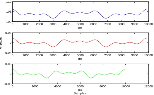
envelopes of signal are shown in Fig.1.
0 1000 2000 3000 4000 5000 6000 7000 8000 9000 10000 100
105 110
(a)
0 1000 2000 3000 4000 5000 6000 7000 8000 9000 10000 -0.05
0 0.05
(b)
A
m
pl
itu
de
0 2000 4000 6000 8000 10000 12000 -0.05
0 0.05
[image:4.612.165.428.494.656.2](c) Samples
In figure 1, the figure (a) is the estimated envelope, figure (b) is the modified envelope, figure (c) is the real envelope. From the figure 1, we can see that the modified envelope almost the same as the real envelope, this means that the proposed method is validity. The relative amplitude error is 3.7% for proposed method and is 4.9% for original method. This means that the proposed method has better performance than the original method.
CONCLUSIONS
This paper proposed an improved independent component analysis by using artificial bee colony method to optimize the original independent component analysis cost function, and used the proposed independent component analysis to detect the parameter of flicker signal. The proposed method had better performance than the original method.
REFERENCES
1. Alrawashdeh, H. and Asumadu, J. 2013. “Adaptive kalman filter for voltage sag detection in power system”, IEEE Jordan Conference on Applied Electrical Engineering and Computing Technologies (AEECT), Amman, Jordan, pp. 1-6.
2. Wang, X. M. Jiang, Y.Q. and C, Huang. 2013. “Flicker detection algorithm based on FFT about error analysis and correction,” Application Research of Computers, 30(9): 2664-2667.
3. Wu, Y. H. 2012. “Compare of the performance between the improved discrete S transform fast algorithm and CWT,” Signal Processing, 28(7):973-978.
4. Liu, Y. and Yang, H. G. 2007. “Voltage flicker detection based on independent component analysis,” Electric Power Automation Equipment, 27(11):34-37.