2017 International Conference on Computer, Electronics and Communication Engineering (CECE 2017) ISBN: 978-1-60595-476-9
EMI: A Rack-scale Memory Interconnection Network Architecture
Ming-che LAI and Xiang-xi ZOU
*College of Computer, National University of Defense Technology, Changsha, China *Corresponding author
Keywords: Rack-scale, Memory, Interconnection.
Abstract. Big data processing applications more and more demand for memory, especially data-intensive applications. The emergence of large-scale storage media supplies for the expansion of memory scale. As a consequence, the interconnection of memories is a key factor to be considered. This paper presents a memory interconnection network architecture for rack-scale supporting for dynamic allocation and expansion of memory, EMI (Elastic Memory Interconnection). EMI’s topology belongs to a hierarchical design approach to extend the network to rack-scale. We also explore the interconnection within every layer, as far as possible to do low latency communications and improve local performance.
Introduction
Big data processing applications need to deal with massive amounts of data, and their performance is not often limited by a processor, but memory or external storage. Due to the performance differences between the processor and memory generated by the "performance wall" [1], the performance of the entire system will degrade. In traditional server architecture, the processor and memory are closely related, and the size of the memory allocated for applications is often limited by the server's own memory size. In the face of big data processing business [2,3,5,6], the traditional computing-centric architecture has been moving towards data-centric transformation. In order to cope with the processing of large amounts of data, in recent years there has been a concept named "In-memory computing". It means that a large amount of data is directly loaded into memory, thereby avoiding many high overhead i/o operations when cpu need to fetch data from hard disk in traditional
architecture.
At the same time, there have been various types of new storage devices such as magnetic ram
(mram) [7], phase change ram(pcram) [8] and another type of ram (rram) based on the electrical and
thermal effects of metal/oxide/metal layer structures [9]. These nonvolatile memory (nvm) can be
used as a replacement or supplement to traditional dram, resulting in lower cost, lower power
consumption, and a more flexible use. Some studies [10] have pointed out that dram consumes up to
40% power of the whole system in many scenes. In addition, dram requires additional safeguards,
including regular backup of data to the hard disk in the background and recovery of data from the hard disk as needed. And the high cost, high power consumption, capacity closing to the upper limit and other unfavorable factors of dram limit its wide range of applications. So it can be considered that nvm memory is mixed with dram or used instead as memory to increase memory density and reduce
power consumption. Or use nvm as the middle layer between the memory and external storage to
achieve the overall system performance and energy efficiency upgrade through a new architecture. In short, the emergence of nvm support more feasibility for the "in-memory computing".
"Loosely coupled resources" means that computing, memory and other resources are not limited to a single server in consequence of flexible resource allocation, improved utilization and convenience of management and upgrade.
In "in-memory computing" architecture, memories locate in different physical servers and they need to be interconnected so as to provide relatively large-scale memory for applications. We call this type of interconnection network as "memory network". "Memory network" should be different from the storage network, which is based on infiniband, ethernet or other peripheral buses. For the high
latency and low news emissivity, they are not suitable for data migration and other big data operations. While the memory network is based on a memory access protocol with a penetration time of about 20ns, much lower than the latency between processor and external pci-e network cards or
external storages. It can also provide enough bandwidth to match the processor's high bandwidth to minimize the performance bottleneck caused by the network. The main work of this paper includes a rack-scale memory interconnection network structure emi.
Related Work
The "blade memory structure" in [11] implements a scalable memory structure with a low degree of coupling through a two-level memory (local and remote) mechanism that supports the dynamic allocation of memory to different servers. The prototype system implemented by this work uses the
pci-e interface to interconnect the compute node and the remote memory node. But the effective
bandwidth of pci-e [12] and the communication delay are easy to become bottlenecks and cannot
match the processor's bandwidth and latency requirements. Memory network’s performance needs to be as much as possible to achieve memory access level requirements, so the communication interface requires a special design, rather than based on pci-e and other existing peripheral interface. At the
same time, the prototype system is smaller in scale, and no more consideration is given to the interconnection between nodes.
There are also many commercial systems that are implementing loosely coupled designs of resources, such as the seamicro structure of a loosely coupled component within a single server [13],
and the loosely coupled structure of intel's rack-scale design [14], rsa (rack-scale architecture). In [4],
the advantages and disadvantages of memory decoupling under different sizes are analyzed. Finally, they hope to build a large "memory pool" in the data center scale. But from the perspective of technological development, many work is gradually extended from small scale to the data center scale. Second, for many big data applications [16,17], smaller-scale (e.g. rack-scale) memory computing systems have been able to meet their needs.
The representative work of the academia is the ramcloud system implemented by stanford
university's research team [15]. By storing the data in ram, cpu accesses data from dram directly in
most of time other than i/o system, significantly improving the access rate and the system’s throughput. Ramcloud expands through the network and meets the actual needs of large-capacity
memory. But it is based on existing networks leading to more remote memory access delay, which is going to be improved. Therefore, in order to achieve high-capacity memory, a viable approach is to expand through the network, but the remote access delay must be reduced.
The results of the study [4] shows that the key to memory interconnect networks is low latency. The interconnection network design, including topology and communication mechanisms, will affect the performance of the entire system. However, there is no interconnection structure specifically designed for "in-memory computing", but existing network structures for data centers or high performance computing (hpc) are worth learning from. The topology includes fat tree (ft) [18],
dragon fly (df) [19], slim sly (sf) [20], torus [21], hypercube (hc) [22] and etc. In the above structure, sf, ft and df are topologies designed for high-radix routers to support scalable interconnection of data
center scale. High-radix topologies can lead to shorter communication distances, thus helping to reduce latency. Torus is a low-level topology and Japan's "k" system and IBM's bluegene/q system
memory network have limited ports which makes it hard to implement high-radix interconnection. So the design of the interconnection structure needs to proceed from the low-radix interconnect structure.
Torus and hc meetsthe request of low-radix and they have good local performance. However, as
the scale of the network expands, their network diameter and average distance increase significantly, resulting in increased latency. To meet the low latency requirements, the fully interconnected network diameter is minimal. The df structure divides the entire network into two levels - the global
layer and the group layer. Nodes within a group are fully interconnected while every group forms a "virtual node" and fully connects with other groups. But it is clear that when the fully interconnected network expands to a certain scale, the cost will be too high and the wiring density will be too large. The main limits of df for memory network comes from port numbers. The sf structure is able to
interconnect more nodes at the same network radix and diameters, but it neither cannot support the race-scale interconnection when the port number (or network radix) is limited within 8 or 10 which is reasonable in memory network.
After analyzing the advantages and disadvantages of df and sf network structures, we mainly
explore the design of memory network under the requirements of low latency and low hops. We finally propose a new type of network structure for rack-scale memory interconnection named emi.
And we also discuss the routing mechanism under the certain topology. The simulation results show the performance among torus, df, sf and emi.
EMI Architecture
Memory Network Architecture
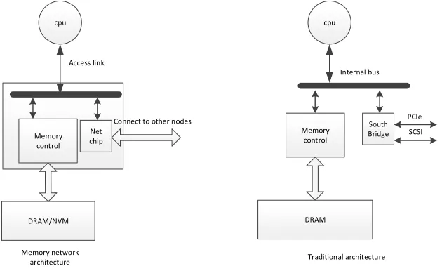
In traditional architecture (Figure 1), the processor accesses the local memory through the memory controller. If the processor is going to fetch data in remote memory, they need to use pci-e network
card and other low-speed equipment, resulting in performance degradation. In memory network, the network function is integrated to the memory controller so as to implement high-speed and efficient accessing to remote memory with some customized network protocol. Due to the highly integrated design, the port number of each node cannot be too much.
cpu
DRAM/NVM
Connect to other nodes Access link
cpu
South Bridge
PCIe Memory
control
DRAM
SCSI Internal bus
Traditional architecture Memory network
architecture Memory
[image:3.612.148.463.462.655.2]control Net chip
Topology
Due to limited number of ports, ft, df, sf cannot directly be used for memory network when it need to
be expanded to rack-scale. Torus and hc can be extended to rack-scale interconnection, but the
diameter of the network will be intolerable.
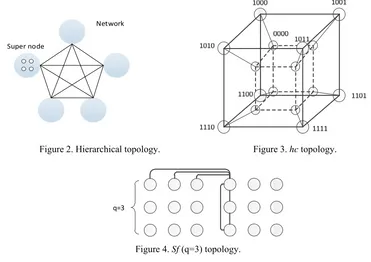
We adopt hierarchical topology (Figure 2) to make the network scalable. In hierarchical topology, some nodes are interconnected to form a supernode (sn); each sn is looked as a "logical node" and
interconnected with other sns to form the entire network. The interconnection way between sns is
considered based on the following two points: 1) guaranteed connectivity among sns; 2) as far as
possible to realize short-range communication. We consider to use hc (Figure 3) or sf (Figure 4)
topology as the way to interconnect nodes within each sn. Because in sf and small-scale hc, the
distance between every two nodes is no more than 4, providing better local performance. In the meanwhile, compared to fully interconnected network, they need less ports to be constructed. For example, interconnecting 18 nodes with sf requests 5 ports per node while the number is 4 to
interconnect 16 nodes with hc. What’s more, each node needs to support 15 ports to interconnect 16
nodes in fully interconnected network.
Super node
Network
[image:4.612.118.489.278.540.2]
Figure 2. Hierarchical topology. Figure 3. hc topology.
q=3
Figure 4. Sf (q=3) topology.
Table 1. The maximum interconnection scale of each type of topo (port number = 8).
topo Number of nodes
SF 50
DF 105
EMI(SF) 972
EMI(HC) 1040
We compare 4 types of topology when the port number is set to 8 in Table 1. In sf we select the q =
5, so each of the two subgraphs contains 25 nodes and a total of 50 nodes are interconnected. In df
there are 5 nodes per group and 21 groups resulting in 105 interconnected nodes. Using the hierarchical scheme proposed here, nodes within per sn are interconnected by sf (q=3) and all sns can
be interconnected at the same time. Up to 54 sns can be interconnected and the maximum number of
hops is 2 within sn. In another way that using hc to interconnect nodes within sn there will be 64 sns
and 16 nodes in every sn. But the communication distance will be up to 4. Thus, the hierarchical
interconnection requirements, and the internal interconnection structure of sn is to minimize the
number of hops in communication and improve local performance.
Routing
When using hc to interconnect nodes within each sn, the nodes can be represented by a 4-digit binary
number (Figure 3). The number of adjacent nodes only have one different bit. And there is only one different bit between vertices of the same location. The highly symmetric node numbering is good for routing design in sn. For example, (0000) need to go through 4 hops to reach (1111) and the middle 3
hops can be flexibly chosen to realize load balancing or deadlock avoiding. When extending to routes between sns, each node needs to be identified by an sn number. There are two ways to route between sns. Packets can be routed internally in sn, and then go into another sn. In another routing way, packes
will first be sent into another intermediate sn and then be routed to destination.
Evaluation and Analysis
We use omnetpp[23] to emulate emi(sf), emi(hc), df and sf structures with approximately 50 nodes in
[image:5.612.179.434.338.478.2]uniform random (all-to-all) traffic where each node is scheduled to intermittently (depending on the injection rate) generate a message at the destination for any other nodes in the network. And we adopt the minimum routing algorithm with the buffers of routers are large enough to support packages’ forwarding.
Figure 5. The average delay of packets in uniform random traffic.
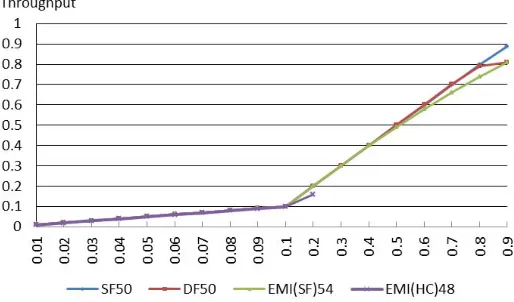
Figure 6. The average throughput in uniform random traffic.
The result (Figure 5) shows that four structures perform well at low injection rates – 13 cycles in
emi (hc) and 6 cycles in anthoer three. The sf network keeps still unsaturated when injection rates
[image:5.612.177.434.520.671.2]do not appear to have bottlenecks on some of them; 2) the distance between any two nodes is no more than 2 hops to achieve low delay in sf. By contrast, the df and emi (sf) network both tend to be
saturated at injection rates of 0.8. It can be found that both two structures contain two layers so the nodes between two layers might become the bottleneck of the network, which could be the reason for saturation of two networks. What much surprises us is that the emi (hc) saturates at injection rates of
about 0.2. This might caused by the hc topology where the maximum distance between two nodes is 4
hops. So the maximum distance between two nodes in different sns will reach to 9.
Figure 6 shows the average thoughput (number of reveived packets per cycle) of four structures at the range of injection rates. With the increase of injection rate, the throughput increases linearly and match to injection rate before network become saturated. We find that emi (hc) tends to be saturated
earlier than others, which is similar to the result of delay performance (Fig 5).
Then we test the performance of emi (sf) in different scale (5, 10, 15, 20 sns), which shows that the
average delay of packets in uniform random traffic can stay around 14 cycles within 0.3 injection rate. So emi (sf) is able to be used for rack-scale memory network with it’s comparable performance and
scalability.
Summary
In the face of rack-scale memory network interconnection, we propose a hierarchical design of the
emi interconnect structure. Compared with the same structure for the df structure, thescalability of emi is more in line with the requirements of rack-scale memory network. In order to optimize the
local communication delay and reduce the number of hops, two kinds of structures (hc and sf) are
proposed to be used in inner layer (sn) interconnection. The evaluation results show that the sf has a
lower number of hops, so it is more suitable as an inner layer interconnection. But the routing design of sf is more complex than hc, which is the future work. The performance of emi (sf) is comparable
with df and sf, but the latters cannot extend to larger scale under the limit of the number of ports. What’s more, it can be seen that the performance of emi (sf) did not degrades much when expande to
larger scale.
We hope that our work can bring more researches on rack-scale memory interconnection network about “in-memory computing”.
Acknowledgements
The authors would like to thank the anonymous reviewers for the feedback and revision suggestions. Then, we would thank China 863 Program (2015AA015302) and NSFC (61572509) for providing the assistance to make this research possible.
References
[1] K. Lim and J. Chang and T. Mudge and P. Ranganathan and S.K. Reinhardt and T.F. Wenisch. Disaggregated Memory for Expansion and Sharing in Blade Servers. In Proc. ISCA, 2009.
[2] Information on http://hadoop.apache.org/. [3] Information on http://memcached.org/.
[4] Han S., Egi N., Panda A., et al. Network support for resource disaggregation in next-generation datacenters [C]// Twelfth ACM Workshop on Hot Topics in Networks. 2013: 1-7.
[6] M. Zaharia, M. Chowdhury, T. Das, A. Dave, J. Ma, M. McCauley, M.J. Franklin, S. Shenker, and I. Stoica. Resilient distributed datasets: A fault-tolerant abstraction for in-memory cluster computing. In Proceedings of the 9th USENIX Conference on Networked Systems Design and Implementation, NSDI’12, pages 2–2, Berkeley, CA, USA, 2012.
[7] G. Sun, X. Dong, Y. Xie, J. Li and Y. Chen. A novel architecture of the 3D stacked MRAM L2 cache for CMPs [C]//In High Performance Computer Architecture, Feburary 2009: 239-249.
[8] L. Chung. Cell Design Considerations for Phase Change Memory as a Universal Memory [C]//In International Symposium on VLSI Technology, Systems and Applications, 2008: 132-133.
[9] S.S. Sheu, M.F. Chang, K.F. Lin et al. A 4Mb embedded SLC resistive-RAM macro with 7.2ns read-write random-access time and 160ns MLC-access capability [C]//In Proceeding of the IEEE International Solid-State Circuit Conference, 2011: 200-201.
[10] Udipi A.N., Muralimanohar N., Chatterjee N., et al. Rethinking DRAM design and organization for energy-constrained multi-cores [J]. Acm Sigarch Computer Architecture News, 2010, 38(3): 175-186.
[11] Lim K., Chang J., Mudge T., et al. Disaggregated memory for expansion and sharing in blade servers [J]. Computer Architecture News, 2009, 37(3): 267-278.
[12] Choi Y.K., Cong J., Fang Z., et al. A quantitative analysis on microarchitectures of modern CPU-FPGA platforms [C]// The, Design Automation Conference. 2016.
[13] SeaMicro Technology Overview.
http://seamicro.com/sites/default/files/SM_TO01_64_v2.5.pdf.
[14] Intel Newsroom. Intel, Facebook Collaborate on Future Data Center Rack Technologies. http://newsroom.intel.com/community/intel_newsroom/blog/2013/01/16/intel-facebook-collaborate -on-future-datacenter-rack-technologies.
[15] Stephen. RAMCloud: Scalable High-Performance Storage Entirely in DRAM [J]. Diego Ongaro Mendel Rosenblum, 1980.
[16] Wang G., Xie W., Demers A., et al. Asynchronous Large-Scale Graph Processing Made Easy [C]// CIDR. 2013.
[17] Shun J., Blelloch G.E. Ligra: a lightweight graph processing framework for shared memory [J]. Acm Sigplan Notices, 2013, 48(8): 135-146.
[18] Hring S.R., Ibel M., Das S.K., et al. On generalized fat trees [C]// Ipps '95, the, International Parallel Processing Symposium, April 25-28, 1995, Santa Barbara, California, USA. 1995: 37-44. [19] Kim J., Dally W.J., Scott S., et al. Technology-Driven, Highly-Scalable Dragonfly Topology [J]. Computer Architecture News, 2008, 36(3): 77-88.
[20] Besta M., Hoefler T. Slim Fly: A Cost Effective Low-Diameter Network Topology [C]// High Performance Computing, Networking, Storage and Analysis, SC14: International Conference for. IEEE, 2015: 348-359.
[21] Dally W., Towles B. Principles and Practices of Interconnection Networks [M]. Morgan Kaufmann Publishers Inc. 2003.
[22] Bhuyan L.N., Agrawal D.P. Generalized Hypercube and Hyperbus Structures for a Computer Network [J]. IEEE Transactions on Computers, 1984, 33(4): 323-333.