2016 International Conference on Wireless Communication and Network Engineering (WCNE 2016) ISBN: 978-1-60595-403-5
A Compact Triangular Slot Array Multiband
Antenna for Wireless Applications
Xiao-ying RAN
1and Zhen YU
1,2,*
1
North China Institute of Science and Technology (NCIST), China
2
Beijing University of Posts and Telecommunications (BUPT), China
*Corresponding author
Keywords: Triangular slot array, Multi-broadband, Compact antenna, CPW.
Abstract. A novel compact triangular slot array multi-broadband planar antenna is proposed for
mobile handsets in the paper. The antenna has an inverted triangle structure radiator with fourteen units triangular slot array and coplanar waveguide (CPW) feed structure. The antenna can cover more than ten mobile applications in three broad-bands with -10dB bandwidth of 69.57% (0.613-1.267GH) for UHF (606-806MHz), GSM900 (880-960MHz), LTE44 (703-803MHz), CDMA2000 (825-880,885-960MHz), 30.17% (1.97-2.67GHz) for DCS1800 (1710-1880MHz),TD-SCDMA (1880-2025MHz,2300-2400MHz), WCDMA (1920-2170MHz,1755-1880MHz), LTE33-41 (1900-2690MHz), Bluetooth, GPS, COMPASS, GLONSS, GALILEO, WLAN (802.11b/g/n:2.4-2.48GHz), and 31.17%(4.17-5.71GHz) for WLAN (802.11a/n:5.15-5.35GHz) wireless applications. The antenna is fabricated on a 1.6 mm-thick FR4 substrate with dielectric constant of 4.4, and the size is 60*55mm2. The good agreement between the measurement results and the simulation validates the proposed design approach and meets the requirements for various wireless applications.
Introduction
Antenna Structure and Design Procedure
Characteristics of Antenna Structure
The configuration of the proposed antenna is shown in Figure 1 with dimensions in Table 1. The antenna has an inverted triangle structure radiator with fourteen units triangular slot array and 50Ω CPW feedline. The antenna is designed on FR4 substrate with height of 1.6mm, dielectric constant (εr)
of 4.4 and loss tangent (δ) of 0.02.
FL H
GNDW
FW GAP N
3.33mm
4.4m m
[image:2.595.223.375.180.342.2]H1
Figure 1. Layout of proposed antenna.
Table 1. Dimensions of proposed antenna (mm).
H1 N FL FW GAP GNDW H
30.5 1.11 25 1 1 55 35
Performance of Simulation
[image:2.595.91.498.492.641.2]The simulation is conducted by Ansoft HFSS 15.0. Figure 2 illustrates the reflection loss (S11) curves at different triangular slot side length coefficient N. Figure 3 shows the voltage standing wave ratio (VSWR) curve of the antenna.
[image:2.595.171.426.653.768.2]Figure 2. Combined simulated reflection loss at coefficient N.
It can be seen that the proposed antenna can operate at four different broadbands centered at 1GHz with -25.3dB reflection loss, 2.5GHz with -18.8dB reflection loss, 4.8GHz with -31.3dB reflection loss, and 7.4GHz with -35.5dB reflection loss. The simulated -10dB bandwidth for the first band (0.613-1.267GHz) is 69.57%, the second band (1.97-2.67GHz) is 30.17%, the third band (4.17-5.71GHz) is 31.17% and the fourth band (5.99-8.3GHz) is 32.33%. These bands cover several commercial application bands of 2G, 3G, 4G, WiFi, Bluetooth, Navigation and WiMAX, as given in Table 2.
Table 2. -10dB frequency bands covered by antenna.
Band No. -10dB
Bandwidth Covered Commercial Bands
1 0.613-1.267GHz ( 69.57%)
UHF(606-806MHz),GSM900(880-960MHz), LTE44(703-803MHz),CDMA2000(825-880,885-960MHz)
2 1.97-2.67GHz
( 30.17%)
DCS1800(1710-1880MHz),TD-SCDMA(1880-2025MHz,2300-2400MHz), WCDMA(1920-2170MHz,1755-1880MHz), LTE33-41(1900-2690MHz),
ISM2.4G(2400-2 483.5MHz),Bluetooth,GPS, COMPASS, GLONSS, GALILEO, WLAN(802.11b/g/n:2.4-2.48GHz)
3 4.17-5.71GHz
( 31.17%) WLAN(802.11a/n:5.15-5.35GHz)
The surface current amplitude distribution on radiator of the proposed antenna that work at the center frequency of 1GHz, 2.4GHz, 4.8GHz, and 7.4GHz, respectively, are shown in Figure 4. For 1GHz frequency, the current is more concentrated at the bottom of the radiator, as shown in Figure 4(a), as the frequency increase, the outer edges of radiator has more current. While for 7.4GHz frequency, the current is relatively maximum at all edges of the radiator, as shown in Figure 4(d).
a)1.0GHz b)2.5GHz c)4.8GHz d)7.4GHz Figure 4. Current distribution of the antenna at different center frequencies
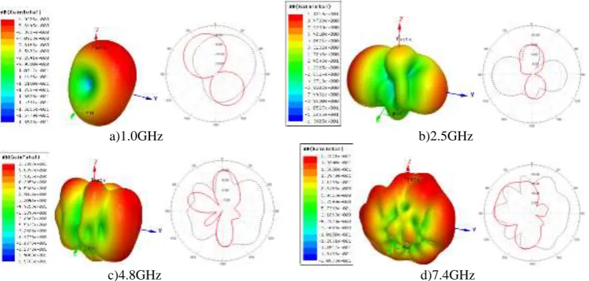
The simulated E/H-plane and 3D radiation patterns of the proposed antenna at the center frequencies of 1GHz , 2.5GHz, 4.8GHz, and 7.4GHz are shown in Figure 5. It can be seen that the patterns are close to omnidirectional at all bands.
a)1.0GHz b)2.5GHz
[image:3.595.85.515.572.777.2]
Fabrication and Measured Results
To verify the muilt-broadband performance of the planar antenna, a prototype antenna is fabricated and measured. The antenna is built on 1.6mm thick FR4 substrate with loss tangent=0.02 and 30μm copper on both sides, as show in Figure 6(a). The antenna is tested by antenna measurement system of PNA3621, as shown in Figure 6(b).
(a) (b) Figure 6. (a) Fabricated antenna prototype and (b)Testing scenario.
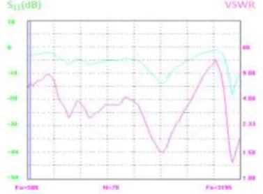
The measured reflection loss (S11) and Voltage Standing Wave Ratio (VSWR) have better
[image:4.595.105.491.164.292.2]agreement with the simulated results, as shown in Figure 7. This makes the antenna compatible for mobile communications applications.
Figure 7. Measured S11 and VSWR curves.
Conclusions
A novel compact fourteen units triangular slot array multi-broadband planar antenna with CPW feed structure is developed for UHF, GSM900, DCS1800, CDMA2000, TD-SCDMA, WCDMA, LTE, Bluetooth, GPS, COMPASS, GLONSS, GALILEO and WLAN applications. The better agreement between the measurement results and the simulation validates the proposed antenna meets the requirements for various wireless applications.
Acknowledgements
[image:4.595.204.393.376.515.2]References
[1] X. L. Sun, L. Liu, S. W. Cheung, and T. I. Yuk, “Dual-band antenna with compact radiator for 2.4/5.2/5.8 GHz WLAN applications,” IEEE Trans. Antennas Propag., vol. 60, no. 12, pp. 5924-5931, Dec. 2012.
[2] M. J.Hua, P.Wang, Y. Zheng, and S. L. Yuan, “Compact tri-band CPW-fed antenna for WLAN/WiMAX applications,” Electronics Letters, vol. 49, no. 18, pp. 1118-1119, 2013.
[3] C. J. Wang and K. L. Hsiao, “CPW-fed monopole antenna for multiple system integration,” IEEE Trans. Antennas Propag., vol. 62, no. 2, pp.1007-1011, Feb. 2014.
[4] H. Chen, X. Yang, Y. Z. Yin, J. J. Wu, and Y. M. Cai, “Tri-band rectangle-loaded monopole antenna with inverted-L slot for WLAN/WiMAX applications,” Electronics Letters, vol. 49, no.20, pp. 1261-1262, 2013.
[5] P. Liu, Y. Zou, B. Xie, X. Liu, and B. Sun, “Compact CPW-fed tri-band printed antenna with meandering split-ring slot forWLAN/WiMAX applications,” IEEE Antennas and Wireless Propagation Letters, vol. 11, pp. 1242-1244, 2012.
[6] W. C. Liu, C. M. Wu, and N. C. Chu, “A compact CPW-Fed slotted patch antenna for dual-band operation,” IEEE Antennas and Wireless Propag. Lett., vol. 9, pp. 110-113, 2010.
[7] D.-G. Kang and Y. Sung, “Coupled-fed planar printed shorted monopole antenna for LTE/WWAN mobile handset applications,” IET Microwaves, Antennas and Propagation, vol. 6, no. 9, pp. 1007-1016, 2012.
[8] Z. L. Xie, W. B. Lin, and G. L. Yang, “Coupled-fed printed antenna for LTE mobile handset applications,” Microwave and Optical Technology Letters, vol. 56, no. 8, pp. 1752-1756, 2014. [9] J. H. Chen, Y. L. Ban, H. M. Yuan, and Y. J. Wu, “Printed coupled-fed PIFA for seven-band GSM/UMTS/LTE WWAN mobile phone,” Journal of Electromagnetic Waves and Applications, vol. 26, no. 2-3, pp. 390-401, 2012.
[10] Z. Chen, Y.L. Ban, J. H. Chen, J. L.W. Li, and Y. J. Wu, “Bandwidth enhancement of LTE/WWAN printed mobile phone antenna using slotted ground structure,” Progress in Electromagnetics Research, vol. 129, pp. 469-483, 2012.
[11] M. T. Wu, and M. L. Chuang, “Multibroadband slotted bow-tie monopole antenna,” IEEE Antennas and Wireless Propag. Lett., vol. 14, pp. 887-890, 2015.
[12] Y. L. Ban, Y. F. Qiang, Z. Chen, K. Kang, and J. L.W. Li, “Lowprofile narrow-frame antenna for seven-band WWAN/LTE smartphone applications,” IEEE Antennas and Wireless Propag. Lett., vol. 13, pp. 463-466, 2014.
[13] C. H. Chang and K. L. Wong, “Small-size printed monopole with a printed distributed inductor for pentaband WWAN mobile phone application,” Microwave and Optical Technology Letters, vol. 51, no. 12, pp. 2903-2908, 2009.
[14] C. L. Nóbrega, M. R. Silva, P. H. Fonseca, et al, “Simple, compact, and multiband trequency selective surfaces using dissimilar Sierpinski fractal elements,” International Journal of Antennas and Propagation, pp. 1-5, Nov. 2015.
[15] A. Kunwar, A. K. Gautam, and B. K. Kanaujia, “Inverted L-slot tripleband antenna with defected ground structure for WLAN and WiMAX applications,” Int. J. Microw. Wireless Technol., Feb. 2, 2016, doi:10.1017/S1759078715001105
[17] L. Peng, C.-L. Ruan, and X.-H.Wu., “Design and operation of dual/tripleband asymmetric M-shaped microstrip patch antennas,” IEEE Trans. Antennas Propag., vol. 9, pp. 1069-1072, Dec. 2010.
[18] W. Hu, Y.-Z. Yin, P. Fei, and X. Yang, “Compact triband square-slot antenna with symmetrical L-strips for WLAN/WiMAX applications,” IEEE Antennas Wireless Propag. Lett., vol. 10, no. pp. 462-465, May 2011.
[19] L. Dang, Z. Y. Lei, Y. J. Xie, G. L. Ning, and J. Fan, “A compact microstrip slot triple-band antenna for WLAN/WiMAX applications,” IEEE Antennas Wireless Propag. Lett., vol. 9, pp. 1178-1181, Dec. 2010.