DECnet™
DIGITAL
Network Architecture
(Phase V)
General Description
Order No. EK-DNAPV-GD
September 1987
This document describes the design of the DIGITAL Network Architecture that serves as a model for Phase V DECnet implementations. It includes descriptions of functions. protocol messages. and operations.
To order additional copies of this document. contact your local Digital Equipment Corporation Sales Office
II
This material may be copied, in whole or in part, provided that the copyright notice below is included in each copy along with an acknowledgment that the copy describes the Digital Network Architecture developed by Digital Equipment Corporation.
This material may be changed without notice by Digital Equipment Corporation, and Digital Equipment Corporation is not responsible for any errors which may appear herein.
Copyright
©
1987 by Digital Equipment CorporationThe following are trademarks of Digital Equipment Corporation:
DDCMP Message Router VAX SPM
DEC PDP VAX VALU
DECmail ReGIS VAX VTX
DECnet RSTS/E VAXcluster
DECnet-DOS RSX-ll VMS
DECnet-ULTRIX RSX-IIM-PLUS VT100
DECnet-VAX ThinWire VT200
DECUS ULTRIX
~D~DamD
DNA UNIBUS
LAN Bridge VAX
MAIL-II VAX CDD
IBM is a registered trademark of International Business Machines Corporation. MVS is a trademark of International Business Machines Corporation.
Contents
Preface
1 Introduction
1.1 Necessity for an Architecture 1.2 Design Goals . . . . 1.3 The Structure of DNA . . . .
1.3.1 Layered Architecture . 1.3.2 The Layers of DNA 1.3.3 Message Flow in DNA 1.3.4 The Naming Service 1.3.5 Network Management 1.4 Relationship of DNA to OSI . 1.5 Relationship to Phase IV
2 Physical Layer
2.1 Physical Layer Functions . . . . 2.2 Physical Layer Functional Modules . . . 2.3 Modem Connect Functional Description
2.3.1 DNA Modem Connect Features. 2.4 X.21 Functional Description
2.4.1 DNA X.21 Features
3 Data Link Layer
3.1 Data Link Layer Functions
3.2 Data Link Layer Protocol Modules 3.3 DDCMP Functional Description
3.3.1 DDCMP Features . . . 3.4 HDLC Functional Description.
3.4.1 HDLC Features.
4 Local Area Networks
4.1 Services Provided . . . . 4.2 Characteristics of the CSMA/CD LAN. 4.3 Relationship to International Standards
4.3.1 Addressing .. . . .. 4.3.2 MultIplexing on ISO 8802-3 LANs 4.4
4.5
Ethernet . . . . Bridges
4.5.1 4.5.2 4.5.3
Bridge Services
Extended LAN Topology Bridge Algorithms . . . . 4.5.4 Bridge Management . . . 4.6 ISO 8802-3 and Ethernet Coexistence.
5 Network Layer
5.1 Network Service Characteristics. 5.2 Network Layer Concepts . .
5.2.1 Hierarchical Routing 5.2.2 System Types .. . 5.2.3 Addressing . . . . . 5.2.4 Subnetwork Types .
5.2.5 Multiple Routing Domains - Static Routing 5.3 Network Layer Functions . . . .
5.3.1 Subnetwork Independent Functions. 5.3.2 Subnetwork Dependent Functions. 5.4 Routing Operation . . . .
5.4.1 The Decision Process . . 5.4.2 The Update Process .. 5.4.3 The Forwarding Process
6 Transport Layer
6.1 Transport Layer Functions. 6.2 Transport Layer Protocols . 6.3 OSI Transport Protocol . .
6.3.1 Connection Establishment 6.3.2 Data Transfer.
6.3.3 Disconnection. 6.4 NSP
6.4.1 Connection Establishment 6.4.2 Data Transfer.
6.4.3 Disconnection.
1 Session Control
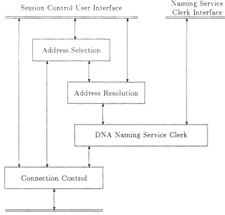
7.1 Functional Description . . . . 7.2 Session Control Functional Components 7.3 Connection Control . . . .
7.3.1 Requesting a Connection by Destination Address 7.3.2 Receiving a Connect Request
7.3.3 Sending and Receiving Data. . . . 7.3.4 Monitoring a Transport Connection . . . . 7.3.5 Disconnecting or Aborting a Transport Connection. 7.4 Address Resolution . . . . 7.4.1 Towers . . . . 7.4.2 Establishing Protocol Sequences for Communication 7.4.3 Maintaining the Towers in the Namespace . . . . 7.5 Address Selection . . . .
7.5.1 Requesting a Transport Connection by Destination Name
8 Naming Service
8 .1 Naming Service Concepts . . . . 8.2 The Semantics and Syntax of Names
8.2.1 The Semantics of Names. 8.2.2 The Syntax of Names . 8.3 Contents of Namespace Entries .
8.3.1 Global Attributes . . . 8.3.2 Predefined Object Classes 8.4 Operational Concepts and Terminology
8.5 Functional Decomposition of the Naming Service 8.5.1 Clerks . . . .
8.5.2 Nameservers
9 Support of X.25
9.1 X.25 Service Functions . 9.2 X.25 Modules . . . . 9.3 X.25 Packet Level . , .
9.3.1 Basic Features of the Packet Level 9.3.2 Optional Facilities of the Packet Level 9.4 X.25 Gateway Access . . . .
9.4.1 X.25 Gateway Access Operation
10 Network Management
10.1 DNA Network Management Model 10.1.1 Entity Hierarchy and Naming 10.2 Network Management Operation . .
10.2.1 Common Management Information Protocol (CMIP) . 10.2.2 Event Logging . . . .
10.2.3 Maintenance Operations Protocol (MOP) 10.2.4 Network Control Language (NCL)
11 DNA Applications
1l.1 Heterogeneous File Access and Transfer 11.2 Network Virtual Terminals
1l.3 Electronic Mail . . . .
11. 3 .1 Mail-II . . . . 11.3.2 Message Router. . . . . 11.4 SI\ A Interconnect Applications
11.4.1 SI\A Gateway Access . 11.4.2 3270 Terminal Emulator 11.4.3 Remote Job Entry . . 11.4.4 Data Transfer Facility 11.5 VMS Services for MS-DOS 11.6 Time Service . . . . 11.7 Computer Conferencing .. . 11.8 VAX System Performance Monitor 11.9 Videotex . . . . 11.10Distributed Queueing
11.11Remote System Management
12 0 SI Upper Layers and Applications 12.1 General OSI Upper Layer Components. 12.2 OSI Applications . . . , . . . .
Glossary Index
Index
VI
89 89 89 90 92 92 92 93 93 93 94 94 95 95
91 97 98
101
Preface
This book is an overview of the DIGITAL Network Architecture (DNA). DNA is a model of structure and functions upon which DECnet implementations are based. DECnet is a family of communications software and hardware products that enable DIG ITAL operating systems and computers to function in a network with other DIGITAL systems and with systems manufactured by other vendors.
A DECnet network is a group of computer systems with associated operating systems, DECnet software, and communication hardware that are connected to each other by phys-ical channels, or lines. Each computer in a network containing a DECnet implementation is called a system. A network therefore consists of connected systems and lines. DNA defines standard protocols, interfaces, and functions that enable DECnet systems to share data and access others' resources, programs, and functions.
The DNA Model incorporates both a set of proprietary protocols and interfaces, and a set of protocols and services defined for Open System Interconnection by the International Standards Organization.
This book describes Phase V of DNA. Phase V provides compatibility with the previous version of DNA, Phase IV.
DNA supports a broad range of applications and a variety of network topologies. (A network topology is a particular configuration of systems and lines.) User documenta-tion and marketing brochures describe in detail various types of applicadocumenta-tion and specific programming and network management information.
This document summarizes the design and structure of DNA and serves as an intro-duction to the DNA functional specifications. It is intended for readers with a knowledge of communications technology who desire an understanding of the overall DNA structure. A glossary at the end of the document defines many DNA terms. Additionally, many DNA terms are italicized and explained in the text at their first occurrence.
Phase V of DNA defines a rich set of functions. Some implementations will not need all of these functions. There are also some aspects of Phase V which may not be present in initial implementations.
Chapter
1
Introduction
The Digital Network Architecture (DNA) defines the means by which computer systems can communicate with each other to form a distributed processing system. It specifies:
• the communication protocols by which systems exchange information, including the rules for constructing and interpreting messages.
• the internal interfaces which allow one protocol to be described and built in terms of the services provided by another.
• the policies and mechanisms by which systems adapt to changing loads and configu-rations to make the best use of available resources.
• the means by which a distributed network can be managed, both locally and remotely.
This General Description relates to Phase V of the DNA model. Phase V is an evolutionary step from the previous version, Phase IV. There are two major new technical directions in Phase V: integration of the OSI standards, and support for increasing network sizes.
OSI ("Open Systems Interconnection") is a set of international standards developed by the International Standards Organization (ISO). Its goal is to allow different vendors' computer systems to be freely interconnected. The standards for the lower layers, providing the basic communications functions, are now substantially complete. DNA uses these OSI standards wherever possible so that Digital computer systems can be used in multi-vendor networks and distributed processing systems.
The increasing importance of networking means that computer networks are continually getting larger. Where a few years ago networks of even a dozen systems were rare, today networks of hundreds of systems are commonplace and several much larger networks, up to tens of thousands of systems, are in use. Furthermore, this increase in the size and number of networks means that they can no longer be operated exclusively by specialists as they have in the past. DNA includes many capabilities to simplify the design, construction and operation of large networks. Of particular importance is the Naming Service, which automates the distribution of critical shared information such as the network addresses of resources, and their protocol capabilities.
:; CHAPTER 1. INTRODUCTION
1.1
Necessity for an Architecture
A system as complex as a DECnet network could not be built without an architecture. The architecture is necessary for several reasons:
• There is a wide variety of computer hardware, communication devices and operating systems. These are built by separate implementation groups. Communication is only possible if they use a common set of specifications.
• Industry Standards (in particular, OSI) are a vital part of computer networking. The architecture specifies how these standards are used and permits individual stan-dards to be introduced and integrated without disrupting the overall function of the network.
• Communications technology is constantly developing. A network product family needs to be able to evolve to include these new technologies. The architecture makes this possible by imposing a modular structure whereby changes in one area do not affect other areas.
• The modular structure of the architecture permits high-performance functions to be implemented in hardware, in a system-independent way. For example, Local Area Network adapters implement the LAN data link protocols.
1.2
Design Goals
DNA was designed to support the following goals.
Conceal network operation from the user. The operation of a large network is nec-essarily complex, but to the user it should appear simple. It then becomes very natural to build distributed applications.
Support a wide range of applications. Almost any application may be distributed across a network. DNA supports a great variety of applications, and allows new ones to be developed freely.
Support a wide range of communication facilities. The technology of data commu-nications is constantly evolving. Not only are greater speeds becoming available, but the nature of the services is also changing. This is clearly illustrated by the devel-opment of Local Area Networks and X.25 packet-switched networks. The structure of DNA allows these new technologies to be integrated and supported without major change to the remainder of the architecture. In Phase V, DNA supports traditional synchronous data links, Local Area Networks, X.25 packet-switched networks and X.21 circuit-switched networks.
1.2. DESIGN GOALS 3
Make maximum use of standards. Standards are critical to successful computer net-works. Wherever feasible, DNA uses OS1 standards rather than proprietary means to attain its goals. Where OS1 standards are being worked on but are not yet approved, DNA is designed to make future migration as straightforward as possible.
Require minimum management intervention. Wherever possible, DNA allows a net-work to operate without operator ot network management intervention. This is par-ticularly important for user-oriented systems, such as personal workstations. The architecture includes algorithms and mechanisms for automatic determination of op-erational characteristics. Examples include the dynamic routing algorithm, and the automatic determination of a system's address.
Be manageable. Some functions cannot be automated, and for those which can it is sometimes necessary to override the automatic choice. This is particularly true for large or complex networks. DNA permits remote management of all network func-tions. The architecture does not impose any particular style of management (such as centralized or hierarchical), but leaves this to the user's choice.
Permit growth. DNA allows a network to grow from just two systems to a huge global network without disruption or major reconfiguration. To the systems attached to the network, such growth is completely transparent.
Permit migration. As new versions of the architecture and its implementations are de-veloped, existing networks must migrate to them. Migration of a large network may take months or even years, and during this period it must continue to operate nor-mally. Each Phase of DNA will fully interwork with the previous Phase. All Phase V systems can communicate with the Phase IV systems in a network throughout its migration period.
Be subsettable. Not all systems need to implement all functions of the architecture. DNA allows an implementation to omit certain functions, particularly those which are expensive to provide and which do not need to be in every system for the network to function.
Be extensible. DNA allows for the incorporation of future technology changes in hard-ware, software and standards.
Be highly available. DECnet networks can be configured to maintain operation even if some lines or systems fail, with minimum prior planning or operator intervention. Be highly distributed. The major functions of DNA, such as routing and network
man-agement, are not centralized in a single system in the network. This in turn increases the availability of the network.
Allow for security. DNA allows for security at several levels. User access control IS
4 CHAPTER 1. INTRODUCTION
1.3
The Structure of DNA
1.3.1 Layered Architecture
DNA is a layered architecture. This means that the functions required to achieve its goals are divided into related and logically coherent groups called layers. The layers are built on top of one another, so that one layer makes use of services provided by the one beneath it. The detailed protocols and other mechanisms of a layer are hidden from the layers above and below - all that is seen by the layer above is the service it provides. This gives the property of layer independence, so that very substantial changes can be made to one layer (such as changing the protocol used) without affecting other layers. A layered architecture is much better able to meet the goals set for DNA than one in which functions are performed in a less structured manner.
I
n-layer clientI
---t--t - - - ---+-t -
n-serVlcen-entity
n-protocol
n-entity n-layer
---+--- -
-
-
-
-
----~--- (n-l )-serviceCommunication through lower layers
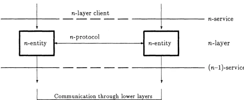
Figure 1.1: Principles of a single layer
Figure 1.1 illustrates the principles of a layer, using the terminology of the OSI Reference Model. It applies to any layer - for generality, the term n-layer is used to refer to an unspecified layer of the architecture. Part of the layer exists in each of the communicating systems. Within one system, the component responsible for the n-layer is called the
entity. The two entities communicate with each other using a protocol, called the n-protocol. This protocol is conveyed using the services of the next lower layer. All layers
provide a data transfer service, although the details vary. Some layers provide additional services such as connection management. In general, the n-protocol is carried as data by the (n-l)-service. The lower layer has no knowledge of, or interest in, the content of the data it conveys. Each n-entity provides the n-service to a local client. The client may be either the (n+l)-layer, or an end-user.
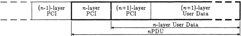
When a layer carries data on behalf of a client, it also adds a header containing Protocol
Control Information (PCI). The PCI contains information which the n-entities need to
[image:12.618.91.491.261.426.2]1.3. THE STRUCTURE OF DNA 5
(n-l )-layer n-layer (n+ 1 )-layer {n+l)-layer
PCI PCI PCI User Data
I.
I.
nPDU n-layer User DataFigure 1.2: Nesting of Protocol Control Information
is called a Protocol Data Unit (PDU) - a PDU of layer n is called an nPDU. Thus a PDU of the Transport layer, for example, is called a TPDU. Often, other names are used for PDUs at a specific layer, such as packet or frame. Since there are several layers involved in providing a service to the user, the data actually sent across a physical channel includes the PCI for several layers, each carried as data by the lower layer. This is illustrated in figure 1.2. In the Data Link layer, some PCI is also carried in a trailer which follows the user data.
The data passed to a layer by its client is called a Service Data Unit (SDU). SDUs pass within a system, between a layer and its client. They are not visible from outside the system. In contrast, PDUs pass between systems, between the communicating entities of a layer. They are visible outside the system as the data flowing "across the wire" between the two communicating systems. Section 1.3.3 describes this in terms of the layers of DNA. In the simplest case, a PDU consists simply of the corresponding SDU together with a header containing PCI. Some layers have the ability to divide an SDU into smaller units, sending each in its own PDU. For example, this allows a layer to convey very large SDUs even though the layer beneath it has a relatively small maximum SDU size.
In DNA, a layer may use more than one protocol, for reasons of compatibility with ear-lier versions or to accommodate alternative option selections from standards. In addition, in some layers one protocol may be a client of another within the layer. A module is an entity which implements a specific protocol, whether or not it is the only protocol in its layer. Each protocol in DNA is defined as a module. A module provides a service to its clients, even if they may be further modules within the same layer.
[image:13.615.118.528.125.186.2]6 CHAPTER 1. INTRODUCTION
Routing mod ule, can access these without having to reflect the options explicitly in their own definition.
1.3.2
The Layers of DNA
OSI Application
DNA Application
Application
Presentation
Naming DNA
Service Session Control Session
Transport
Network
Data Link
Physical
Figure 1.3: The Layers of DNA
Figure 1.3 shows the layers of DNA and their relationship. These are further described below.
Physical layer. The Physical layer is concerned with transmission and reception of data on the transmission medium. Its functions include:
• Conversion of data to and from electrical signals.
• Monitoring signals from the communication channel, such as modem signals.
• Bit level synchronization, either by direct generation and recovery of the clock signals or using an external clock (for example, from a modem).
• Management of Physical layer connections, such as dialup lines and X.21 circuits. The Physical layer provides the mechanisms for this but the policies (when to initiate and terminate a circuit) are administered by the Network layer.
[image:14.617.117.429.140.340.2]1.3. THE STRUCTURE OF DNA 7
Data Link layer. The Data Link layer provides a dependable communication path be-tween directly-connected systems in a network. It operates protocols which detect errors induced in the Physical layer (for example by electrical disturbances). This layer also corrects such errors where the anticipated error-rate is high, for example on synchronous lines.
DNA defines three protocols for this layer. DDCMpTM and HDLC operate over synchronous lines. DDCMP is a Digital-defined protocol used in previous Phases of DNA, which can also operate over asynchronous lines. HDLC uses selected features of the ISO standards. A subset of this protocol is compatible with LAPB, used in X.25. Over Local Area Networks, DNA uses ISO 8802-2 and -3, which are identical with the corresponding parts of IEEE 802, and can also use the Ethernet standards for compatibility with Phase IV.
Network layer. This layer routes user data between systems in the network. In DNA, this layer provides the Connectionless-mode Network Service (CLNS) of as!. Each piece of user data (that is, each NSDU) travels through the network in a self-contained packet, containing its destination and source addresses and other required informa-tion. The protocol used is the ISO Internetwork Protocol (ISO 8473). This layer exists both in the communicating systems and also in the routers which join together the data links forming the network. The Network layer also maintains the databases needed to find routes through the network from a source to a destination. To make this possible, it operates a dynamic adaptive routing algorithm which automatically adapts the routes to the current topology of the network. This algorithm is defined in the DNA Network Routing specification. It allows for networks of several hundred thousand systems. The Network Routing specification also contains the mechanisms for using the various kinds of communications media, such as LANs, synchronous circuits and X.25 networks, and for interworking with other (non-DNA) networks that also use the OSI protocols.
DNA also provides the Connection-mode Network Service (CONS) in systems which are directly attached to an X.25 Wide Area Network, or which have access to such a network through the X.25 Gateway Access Protocol.
Transport layer. This layer provides a reliable end-to-end service between communicat-ing systems, concealcommunicat-ing from its users the detailed way in which this is achieved. This layer (and all higher layers) operates only in the communicating systems. Its functions include:
• Recovery from data loss, where the Network layer fails to deliver a packet (for example due to congestion), by retransmission.
• Flow control, to match the transmission rate to the reception rate.
8 CHAPTER 1. INTRODCCTION
• Segmentation and reassembly of user messages, so that there is no limit to the size of user messages (TSDUs) even though the size of network messages (NSDUs) is limited.
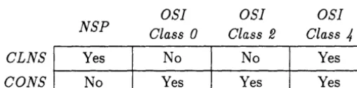
DNA contains two protocols for this layer. NSP (Network Services Protocol) is a Digital-defined protocol which was first defined for DNA Phase I. The 051 Transport Protocol (ISO 8073) is used for the first time in Phase V. Digital systems use Class 4 of this protocol, which can operate over both the Connectionless-mode and Connection-mode Network Services. DNA also describes the uses of Classes 0 and 2, for use only over the CONS.
Above the Transport layer, DNA permits two alternative modes of access. Proprietary and user-developed application protocols use the DNA Session Control layer. Standardized application protocols use the OSI Session, Presentation and Application protocols. DNA Session Control. This provides the logical links (that is, connections) which are
seen by the application programs. For data transfer, these provide the functions of the Transport service. Session Control's additional functions are concerned with the initiation of a logical link and its management within a system. The most important functions of this layer whose operation is specified by the architecture are:
Name to address translation. Remote objects are addressed by their object name.
Session Control translates the name into the addresses used at each of the proto-col layers, and in particular the Network address which allows the Network layer to send traffic to the correct remote system. For compatibility with Phase IV, objects may also be addressed using a node name which identifies the remote system, and a means to identify an object within the system.
Protocol selection. At several layers, DNA provides a choice of protocols. Partly, this is for compatibility between Phases, and partly it is to permit communication with non-DNA systems which have different choices in their selection of OSI options. When Session Control performs the object name translation, it also obtains information about the protocols which can be used. This is compared with the capabilities of the local system, and a mutually compatible protocol set is selected.
Access control. Session control provides features whereby remote users can be identi-fied. In conjunction with system-specific access control mechanisms, this allows access to particular objects to be restricted to a limited set of remote users.
In addition, the Session Control layer is where system-specific logical link initializa-tion funcinitializa-tions are performed. These include process addressing and process activa-tion.
1.3. THE STRUCTURE OF DNA 9
User access IS In general provided at the application layer, although some imple-mentations may provide direct access to the services of the Session and Presen tation layers.
User access to DNA modules is not restricted to the DNA and aS! application layers. For example, there are several applications which make direct use of the Data Link layer, to meet specialized requirements in a LAN environment.
1.3.3 Message Flow in DNA
TSDUs
TPDUs
Transport Layer
---~---NSDUs NPDUs Router
(packets) . . . - - - ,
t o 4 - t - - - + t
---~---DPDUs (frames)
Network Layer
Data Link Layer
- - - -
-- ----
---J I
Physical channel Physical channel
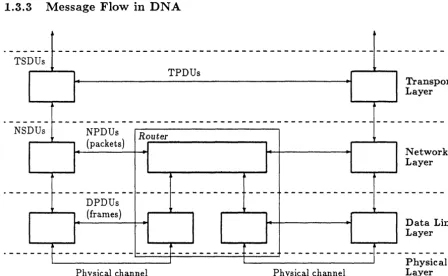
Figure 1.4: DNA Message Flow
Physical Layer
Figure 1.4 shows how messages flow between DNA systems. At the Data Link layer, com-munication is strictly between directly connected systems. The messages passing between entities at this layer are Data Link PDUs (DPDUs), which are often called frames. At the Network layer, routers pass traffic from one data link to another on the path from one system to another. The messages at this layer are Network PDUs (NPDUs), often called packets. Routers examine the NPDUs to determine the next part of the route, and update some parts but largely pass them on unchanged. NPDUs passing between Network Layer Entities correspond to Network Service Data Units (NSDUs) which pass between the Network layer and the Transport layer.
[image:17.618.108.556.185.461.2]10 CHAPTER 1. INTRODUCTION
and its users is in Transport Service Data Units (TSDUs). The user will normally be either DNA Session Control or the OSI Session layer.
1.3.4
The Naming Service
The name translation and protocol selection functions of the DNA Session Control layer require a large database containing information about all systems in the network. It would be an impractical task for each system to keep its own copy of this database, particularly in a large network. DNA therefore includes a network-wide Naming Service, which can store all names having network-wide significance. Any name can be accessed and its associated attributes (such as network addresses) can be retrieved, from any point in the network. Every name is unique. A hierarchical directory structure (similar to a filestore directory structure) simplifies the task of assigning unique names.
N ames are physically stored in directories. In general, a directory is replicated, that is, stored on more than one physical system. This protects against hardware failure (for example, disk crashes) and also makes the information accessible even during temporary network problems. The Naming Service contains the mechanisms needed to ensure that the copies of directories become synchronized as changes occur.
A major use of the Naming Service is to maintain the database of object names, and associated addresses and protocol selection information, which Session Control uses. How-ever, it is not constrained to this application, and can be used by any application which requires names to have unique network-wide significance.
The Naming Service is both a component of DNA and also a user of it. Communication between the Name Servers which provide the service uses the normal services of DNA through Session Control.
1.3.5
Network Management
DNA provides powerful distributed network management facilities which allow network components to be managed remotely. The network management facilities available include:
• Configuring the network components within a system, for example to determine how its physical links are to be used.
• Setting operational parameters such as timer values and resource limits.
• Examining configuration information and the operational parameters.
• Examining counters of diagnostic information such as messages sent and received and error conditions.
• Generation of events which can be collected and analyzed at a remote site, such as circuit failures and recovery.
1.4. RELATIONSHIP OF DNA TO OSI 11
Each system in the network, and each component (such as a protocol module) within a system, contains a network management agent. The agent accesses information held by the component, to report on it or to modify it. The information which is kept by each component, and how it may be modified and used, is specified by the corresponding part of DNA. Each system has a unique agent called the node agent which receives requests from other systems and dispatches them to the appropriate part of the system.
Network management is used through a director. DNA defines a network management command language called NCL which corresponds closely to the architected structure of a system. A program which provides an NCL interface to a user is an example of a director. A director may either be local (that is, running on the system it is managing) or remote. A local director can be used to perform management operations when the system is not yet part of a network, for example during system initialization. A remote director communicates with the system it is managing using the following protocols.
Conunon Management Information Protocol (CMIP). This is used for communi-cation betwee~ a director and the target node agent. It provides an encoding of the network management operations which can be performed, and their parameters. For example, an operation might be "read counter" and the parameters would be the name of the counter and the name of the system component in which it resides. CMIP is a client of the Session Control layer , and operates in the same way as any other DNA application protocol.
Maintenance Operations Protocol (MOP). This is used for low-level communication when a system is not fully operational. It is a client of the Data Link layer. Its most important functions are the triggering and execution of down-line load and up-line dump, and link-Ievelloopback functions.
Event Logger Protocol. This is a particular fonn of CMIP, used by the node agent to report events when this has been requested by a director. Like CMIP it operates as a DNA application protocol.
Network Information and Control Exchange (NICE). This is the protocol used by Phase IV for management communication. It is supported by NCL for management of Phase IV systems during the migration period.
1.4 Relationship of DNA to OSI
12 CHAPTER 1. IXTRODUCTION
Physical layer. The DNA Physical layer has always been based on available standards, which are implemented in hardware devices. These include, EIA RS-232-D (and the corresponding ISO standards and CCITT Recommendations) and the Ethernet standards as now reflected in ISO 8802-3 and IEEE 802.3.
Data Link layer. The version ofRDLC which is used in DNA uses ISO 4335 and ISO 7809. For Local Area Networks, DNA uses the Logical Link Control protocol of ISO 8802-2 and IEEE 802.2.
Network layer. The ISO Protocol for Providing the Connectionless-mode Network
Ser-vice, ISO 8473, is used for data transfer. Exchange of routing information between
end-systems and routers uses the ISO End System to Intermediate System Routing Protocol, ISO 9542. The Connection-mode Network Service, where used, is provided
using the X.25 Packet Layer Protocol, as defined in ISO 8208 and the mapping defined in ISO 8878. The addresses used by the DNA Network layer follow the corresponding OSI standard, ISO 8348 Addendum 2.
Transport layer. DNA includes Class 4 of the OSI Transport Protocol, ISO 8073. Classes
o
and 2 are also available, for use over the CONS. The service provided to a DNA Application corresponds to the OSI Transport Service, ISO 8072. This service is also used by applications which use the OSI upper layer protocols.Above the Transport layer, OSI protocols are available as an alternative but are not used for all applications. There are several reasons for this:
Functions available. DNA supports many applications and their protocols. Only a few of
these are under study for OSI standardization.
State of the standards. At the time of writing, the only OSI upper layer standards which
have been approved as an International Standard are those for the Session layer. The others are at various stages of drafting, and are therefore subject to further change before final approval.
Compatibility. Communication with previous implementations is essential and can only be
done using the proprietary protocols.
In Phase V of DNA, specific implementations of upper layer standards will be included as they become available. Development of an integrated DNA architecture for the OSI upper layers will take place during the lifetime of Phase V, reflecting the progress of the standards themselves.
The DNA network management protocols are based closely on early drafts of ISO's work on the subject. The CMIP protocol used in DNA is based on drafts of the ISO CMIP protocol (ISO DP 9596), and uses the OSI Remote Operations Service (ISO DP 9072) and the OSI Presentation protocol (ISO 8823 and ISO 8825).
1.5. RELATIONSHIP TO PHASE IV 13
1.5
Relationship to Phase IV
In keeping with the goals of DNA, a system which implements Phase V is fully able to communicate with a Phase IV system. A Phase IV network can be migrated gradually to Phase V without requiring closely synchronized changes to multiple systems. All of the protocols used in Phase IV are included in Phase V systems, although in many cases they will be used only for communication with Phase IV systems. To the user of a DECnet network, the change from Phase IV to Phase V will not be apparent, except that the new functions of Phase V will gradually become available.
A summary of the major changes between Phase IV and Phase V is given below.
Terminology. The names of some layers have changed from Phase IV: • The Network layer was called the Routing layer.
• The Transport layer was called the End Communications layer.
• The Physical layer was called the Physical Link layer.
These changes have been made for alignment with the names used in
as!.
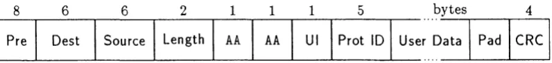
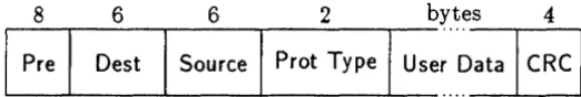
Local Area Networks. Phase V uses the frame format defined by ISO 8802-2 and -3 and IEEE 802.2. This differs slightly from the Ethernet frame format used in Phase IV. DNA systems automatically use the correct format for communication with other systems on the same LAN. A Phase V system always transmits and receives in ISO format, and also listens for frames in Ethernet format. If there are Phase IV systems on the LAN (that is, if Ethernet format frames are received) then it also transmits using Phase IV format when necessary.
Data Link protocols. Phase V supports HDLC as well as DDCMP. A circuit must be configured to use the same protocol as the remote system, otherwise it will fail to initialize.
Network layer. There are many changes to the Network layer in Phase V, to accom-modate the OSI standards and to permit larger networks. These are described in Chapter 5.
Transport layer. Phase V supports the OSI Transport Protocol as well as NSP. A com-mon interface is presented to the user of the Transport layer. Selection of the correct protocol, for communication with another DNA system, is performed by the Ses-sion Control layer. For communication with non-DNA systems, the OSI Transport Protocol is always used.
14 CHAPTER 1. INTRODUCTION
Chapter
2
Physical Layer
The Physical layer provides mechanical, electrical, functional and procedural means to ac-tivate, maintain and deactivate physical connections between directly connected systems, and for Physical layer clients to transfer data. Functions of the layer include encoding and decoding signals on the physical interface, bit synchronization of received data, bit trans-mission, and interfacing the communications channel to the processor and memory used to implement higher layer protocol functions. Implementations of this layer encompass hard-ware interface devices and device drivers in operating systems, as well as communications hardware such as modems, transceivers, and the physical communications links themselves.
Protocols for the Physical layer are rudimentary. No special Physical layer standards have been developed for DNA. Instead, it relies on industry standards for the Physical layer, thereby ensuring that DECnet products can operate over available technologies and physical networks. Physical layer standards supported by DNA for wide area networks include the EIA RS-232-D and RS-423 specifications, and the CCITT V.24 and X.21 bis specifications. Physical layer standards supported by DNA for Local Area Networks include two baseband implementations of the ISO 8802-3 LAN, the original and the Thin Wire
™
specifications, and a broadband implementation.Phase V of DNA defines the functions and operation of the Physical layer more com-pletely than earlier versions of the architecture. The way in which industry standards for the layer are integrated into DNA is fully described. Network management of the Physical layer, which in Phase IV was bound to the management of Data Link layer protocols, has been rationalized and enhanced.
DNA support for CCITT Recommendation X.21 has been added to Phase V, allowing implementations of DECnet access to and use of the facilities of X.21 circuit switched public data networks. The architecture for X.21 has been closely aligned with that for modem connect type lines, such that a common set of services is presented to the higher layers of DNA.
The DNA Physical layer is structured in a modular way, allowing support for other Physical layer standards, such as those for ISDN, to be added in later versions.
16 CHAPTER 2. PHYSICAL LA YER
2.1
Physical Layer Functions
The following functions are performed by Physical layer modules.
Connection establishnlent and release. These functions are provided where a com-munications link is attached to a circuit switched wide area network such as an X.21 or public telephone network. They allow physical connections to be dynamically established and released.
Bit synchronization. This function establishes synchronization with an incoming bit stream, and thereafter clocks data in from the communications channel at the correct rate.
Data transfer. The Physical layer provides a bit stream service interface where data is passed across the interface in I-bit units. On the transmit side, data bits passed by the client are clocked onto the communications channel. Conversely on the receive side, bits are clocked in from the channel and presented to the client. The Physical layer maintains sequence; data bits are delivered in the same order in which they were submitted. A communications link may allow full-duplex or half-duplex transmission.
Fault notification. This function reports fault conditions to Physical layer clients.
Management. These functions allow network management to control and monitor the operation of the Physical layer, for example to set operating characteristics of com-munication links, activate and deactivate physical connections, monitor the status of active connections and perform loopback. Physical layer modules maintain manage-ment counters and report significant events.
2.2
Physical Layer Functional Modules
The DNA Physical layer contains a number of functional modules, one for each type of communications interface supported by DNA. These modules interface with the commu-nications channel and make Physical layer services available to the higher layers of DNA. Many of the functions performed at the Physical layer are common across all the modules although details vary in each case. The modules comprise functions to get and set DTE-DCE interchange circuit signals, where applicable, and functions to transmit and receive data. At this level, internal system requests are mapped onto electrical signals on the communications channel. These functions are media specific. For example, the transmit function for a CSMA/CD LAN differs from that for an X.21 interface.
Currently, the DNA Physical layer defines functional modules for the following com-munications interfaces:
• Modem Connect. This is described in Section 2.3.
• X.21. This is described in Section 2.4.
2.3. MODEM CONNECT FUNCTIONAL DESCRIPTION 17
2.3
Modem Connect Functional Description
DNA Modem Connect is the name given to the Physical layer module which defines how DNA operates over communication links conforming to industry standards for modem connection. There are a number of these standards, each with different characteristics. However, the standards encompassed by DNA Modem Connect are sufficiently similar to be covered by a single architectural module. Differences between the standards are treated as variants within this general module for modem connection.
DNA Modem Connect defines how the Physical layer services provided by switched and leased lines are integrated into DNA. It defines the mechanisms which allow higher layers of DNA to use these services, and for network management control and monitoring of lines. The module supports a number of the industry standards for the layer, including EIA RS-232-D and CCITT V.24, and CCITT V.25 and V.25bis for auto call and auto answer. The module also defines null modem operation, where only the data interchange circuits are used.
2.3.1
DNA Modem Connect Features
This section describes some of the major features of DNA Modem Connect.
2.3.1.1 Call Control Services
DNA Modem Connect defines services which permit the control and monitoring of switched line connection establishment and release. This allows clients to make outgoing calls, handle incoming calls and clear calls. The progress of an outgoing call attempt may be monitored, and reason information is returned if the call fails to connect. Call control services do not apply to leased line connections.
2.3.1.2 Data Transfer Services
DNA Modem Connect defines services which permit the higher layers of DNA to transmit and receive data on leased and switched lines, and to control line turnaround operations on half-duplex communications links. These services are used by the Data Link layer.
2.3.1.3 Call References
DNA Modem Connect uses call references to identify calls locally. Call references are values assigned by DNA Modem Connect to outgoing call attempts placed to the network and incoming calls which successfully connect. Each value is unique, allowing every call (attempt) to be unambiguously identified. By identifying calls in this way, a number of additional features are possible. In particular, call references provide:
18 CHAPTER 2. PHYSICAL LAYER
• A means by \vhich management information for the call signaling and data transfer phases can be correlated by network management.
2.3.1.4 Call Sharing
DNA Modem Connect provides a feature which permits calls on a switched line to be accessed by more than one client. This is known as call sharing. Call sharing allows, for example, DNA MOP and the Network layer to utilize the same line. When call sharing is used, clearing is coordinated by DNA Modem Connect such that a request by one client to clear a call does not have immediate effect if it is still in use by others.
2.3.1.5 Network Management
In Phase V, a Line management entity :s defined which contains Physical layer management attributes. These include speed attributes to control primary and fall-back transmission rates, type attributes which define line and modem capabilities (null modem, switched or leased line), a communications mode attribute denoting asynchronous or synchronous op-eration and an attribute to control the transmission encoding technique used, for example, NRZI encoding.
2.4
X.21 Functional Description
X.21 is a Recommendation of the International Telegraph and Telephone Consultative Committee (CCITT). It describes the electrical, mechanical and procedural interfaces between Data Terminal Equipment (DTE) and Data Circuit-terminating Equipment (DCE) for operation over synchronous public data networks.
X.21 defines two types of service: leased circuit and circuit switched. The leased circuit service provided to higher layers is equivalent to that provided by more traditional leased line services. In its simplest form, two DTEs attached to the network are connected point-to-point. The circuit switched service is akin to that provided by the telephone network. A DTE attached to the network controls the establishment and release of physical connections to other DTEs. The establishment and release procedures are defined by X.21, with the call set-up phase involving the exchange of address and facility data with the network. Higher layer data is carried transparently over leased and established circuit switched physical connections.
DNA X.21 defines how the services provided by X.21 networks are integrated into DNA. It defines the mechanisms which allow higher layers of DNA to use these services, and for network management control and monitoring of subscriber lines. DNA X.21 supports leased circuit and circuit switched connections.
2.4.1
DNA X.21 Features
2.4. X.21 FUNCTIONAL DESCRIPTION 19
2.4.1.1 Call Control Services
DNA X.21 defines services which permit the control and monitoring of X.21 circuit switched connection establishment and release. This allows clients to make outgoing calls, handle incoming calls, access call information and clear calls. Call control services do not apply to leased circuit connections.
Clients can request the use of outgoing call facilities such as reverse charging or closed user groups on a per-call basis. CUG and other facilities, if available from the network, may be used to set up incoming call selection criteria which limit the incoming calls reported to a client to those matching the criteria, for example to calls specifying a particular CUG. Call control services allow a client to monitor the progress of an outgoing call attempt and obtain reason information from the network if the call fails to connect. When a call connects, the client can request full details of the call as it was actually established, for example if it was redirected and if so, where to.
2.4.1.2 Data Transfer Services
DNA X.21 defines services which permit the higher layers of DNA to transmit and receive data on leased circuit and circuit switched connections, and to control half-duplex opera-tions where these are supported by the network. These services are used by the Data Link layer.
2.4.1.3 Call References
DNA X.21 uses the call reference mechanism as described in Section 2.3.1.3. 2.4.1.4
DTE
SharingDNA X.21 provides a feature which permits a subscriber line to be shared by more than one client. There are two variants of this: call sharing, in which many clients are permitted access to the same call, and line sharing, in which only one client has access to any single call. DTE sharing allows, for exa.mple, DNA MOP and the Network layer to utilize the same subscriber line.
Line sharing is only possible if the network provides Closed User Group and/or sub·
addressing facilities enabling different selection criteria to be set for each client. When call
sharing is used, clearing is coordinated by DNA X.21 such that a request by one client to clear a call does not have immediate effect if it is still in use by others.
2.4.1.5 Network Management
DNA X.21 provides a comprehensive set of network management features allowing control of subscriber lines, use of optional facilities, selection of operating procedures and the definition of outgoing call parameter and call selection parameter profiles or templates.
20 CHAPTER 2. PHYSICAL LA YER
allows, for example, the direct call number t.o he. se.t or incoming calls to be redirected to another DTE.
Chapter 3
Data Link Layer
The Data Link layer provides means to establish, maintain and release data link connections
between two directly connected systems, and for Data Link layer clients to transfer data. Mod ules in the Data Link layer co-operate to provide this logical communications path by use of a data link protocol. A data link protocol defines formatting rules and procedures for data transmission and reception over a physical communications link. In the absence of errors from the communications link, the task of the data link protocol is relatively simple. Once errors occur, however, data corruption and loss are possible, introducing synchronization problems between the transmitter and receiver. A data link protocol designed to operate under these conditions has error detection and recovery procedures. Data Link layer clients are notified of persistent or unrecoverable errors.
Data Link layer protocol modules use the services of the Physical layer described in Chapter 2 to transmit and receive data on communications links. Physical layer services to control operation of the link are also used. For example, when operating over a half-duplex modem connect line, a Data Link layer module uses Physical layer services to control line turnaround between transmit and receive modes.
3.1
Data Link Layer Functions
The following functions are performed by the Data Link layer.
Connection establishment and release. These functions are provided where the Data Link layer module supports a connection mode type of operation. They allow syn-chronization of data link operation with a peer module prior to data transfer, a process called data link connection, and termination of the connection when it is no longer required.
An alternative mode of operation called connectionless is supported by some Data Link layer modules. In this case, there are no establishment and release phases; the recipient of data is determined from addressing information supplied by the client with each service data unit.
22 CHAPTER 3. DATA LINK LAYER
Data transfer, User data is passed between the Data Link layer and clients in service data units. On the transmit side: this user data is enveloped with protocol control information before being sent. On the receive side, the control information is ex-tracted before presentation of the data to the client. There is a one-to-one mapping of service data unit to protocol data unit.
Framing and synchronization. The synchronization functions assemble received Phys-icallayer service data units (bits) into larger units (bytes and messages). The framing function detects the beginning and end of protocol messages, once synchronization has occurred.
Sequence control. This function uses sequence numbers in the protocol to ensure that the sequential ordering of data transmitted on the data link connection is maintained. It does not apply to connectionless operation.
Error detection. This function detects transmission, format and procedural errors on the data link connection.
Error recovery. This function attempts to recover from transmission, format or proce-dural errors. Persistent or unrecoverable errors are reported to the Data Link layer client. It does not apply to connectionless operation.
Flow control. This function limits the rate at which data is sent or received on the data link connection. It does not apply to connectionless operation.
Identification and parameter exchange. This function enables the exchange of iden-tification and operational parameters over the data link connection, typically prior to user data transfer. This function may include parameter negotiation.
Use of Physical layer services. The Data Link layer uses the services of the Physical layer to transmit and receive data, and where applicable, to control the operation of the communications link.
Management. These functions allow network management to control and monitor the operation of the Data Link layer, for example to set data link protocol operating characteristics, enable and disable data link connections and monitor the status of enabled connections. Data Link layer modules maintain management counters and report significant events.
3.2
Data Link Layer Protocol Modules
Currently, the following protocol modules are defined in the DNA Data Link layer:
• Digital Data Communications Message Protocol (DDCMP). This is de-scribed in Section 3.3.
• High-Level Data Link Control (HDLC). This is described in Section 3.4.
3.3. DDCMP FUNCTIONAL DESCRIPTION 23
3.3
DDCMP
Functional Description
DDCMP was designed in 1974 by Digital specifically for DNA. It is a general-purpose, byte-oriented data link protocol which is designed to serve the needs of inter-computer data communications in a wide variety of applications and environments.
DDCMP operates over synchronous or asynchronous, switched or non-switched com-munications links. It can operate in point-to-point configurations or in multipoint configu-rations in which communication takes place between a control station and each of several
tributary stations. DDCMP messages are framed as sequences of bytes, beginning with
a single control byte indicating the message's starting point and type (data or control). While DDCMP control messages have a fixed length, data messages have variable lengths, indicated by a length field. On reception, this encoding allows the receiver to determine the beginning and end of messages. The encoding also allows user data transparency; data containing bit patterns that are those of control characters is not misinterpreted by DDCMP. Incoming bits are assembled into bytes using start/stop bits for asynchronous links and synchronization characters for synchronous links.
DDCMP uses two 16-bit cyclic redundancy checks (CRC-16); one to detect errors in the protocol header, and a second to detect errors in user data. On half-duplex or multipoint links, DDCMP executes link allocation procedures to ensure that two or more stations do not conflict in their use of the link. These techniques are based on polling in which one station gives permission to the other to transmit. DDCMP uses timers and sequence numbers to detect and recover from lost messages; it also prevents the process of error recovery from creating duplicate messages. The Network layer uses the error detection and retry capability of DDCMP to verify that links between directly connected systems are operational and to synchronize the operation of the routing protocols.
DDCMP makes efficient use of high speed communication links, such as satellite links, to provide high data throughput.
3.3.1 DDCMP Features
This section describes in more detail some of the major features of DDCMP and how they affect the operation of the protocol.
3.3.1.1 Link Management
Link Management resolves transmit contention on half-duplex point-to-point and multi-point links. In the half-duplex multi-point-to-multi-point case, one station transmits while the other receives. The switching between transmit and receive modes is accomplished by a selection
flag in DDCMP messages. The transmitting station sets the flag in the last message sent,
24 CHAPTER 3. DATA LISK LAYER
Tributary stations transmit only when selected to do so by the control station. Like the half-duplex point-to-point case, this is done using the selection flag. Messages sent by a tributary to the control station are seen and ignored by all other tributaries. The control station receives the message and verifies that it has come from the selected station. Tributary stations may not exchange data directly; all traffic is between the control station and the tributaries.
3.3.1.2 Message Exchange
The message exchange feature of DDCMP is that part of the protocol which provides sequential, error-free data transfer. DDCMP is a positive acknowledgment retransmission protocol. For each data message correctly received and passed to the client, a positive
acknowledgment is returned on the link to the transmitter. If incorrectly received, the message is not passed to the client. Instead, an error recovery mechanism is invoked causing message retransmission. DDCMP uses the CRC-16 cyclic redundancy check for error detection on protocol headers and user data.
The basic message exchange mechanism uses data message sequence numbers, a positive acknowledgment control message (ACK) and a timer. However, DDCMP has additional control messages and operational techniques to achieve higher performance and faster error recovery.
Negative acknowledgment (NAK). The duration of a timer used to detect an error when an ACK is not returned, must be long enough to account for propagation delay, line turnaround and processing of the data message and ACK generation by the receiver. Typically, values of a few seconds will be used. However, DDCMP uses a negative acknowledgment mechanism which, for most error conditions, enables retransmission to take place before the timer expires, making more efficient use of link resources. This mechanism is used by the receiver when it does not correctly receive a message but does recognize that one was sent to it. Under these conditions, a NAK control message is returned, initiating retransmission.
Reply to message number (REP). If the timer expires, this probably means that the returned ACK was lost or corrupted. In this case, rather than retransmit perhaps a large amount of data, a REP control message is sent containing the number of the previous message. This forces the transmitter and receiver to synchronize their numbering and to cause retransmission if required. If the message with that number was received correctly, the response to REP is an ACK; otherwise it is a NAK. NAK causes retransmission to occur.
Pipelining. Pipelining is a technique which allows further messages to be sent while awaiting acknowledgment of ones previously transmitted. To achieve this, DDCMP messages are numbered from 0 to 255. The numbering is cyclic {modulo 256)1
3.3. DDCMP FUNCTIONAL DESCRIPTION 25
Piggybacking. The purpose of an ACK is to convey the message number of the last suc-cessfully received data message. If data traffic is being transmitted in both directions, this message number can be carried in a message sent in the reverse direction. This technique is called piggybacking, and saves the framing overhead for a separate ACK message.
ACK implied in NAK. Like an ACK, a NAK contains the message number of the last message successfully received. Therefore, as well as indicating an error, receipt of a NAK implies acknowledgment of previous messages.
Initialization. The process of setting message numbers to initial values is called initial-ization. It is accomplished by use of STRT (Start) and STACK (Start Acknowledge) control messages. Initialization is carried out at link start-up time or after a failure, to reset the message numbers at both ends of a data link connection to zero. The protocol is designed so that one end of a connection cannot be initialized without the other.
3.3.1.3 Maintenance Mode
In maintenance mode, DDCMP provides a connectionless service to the DNA Mainte-nance Operations Protocol (MOP). In this mode, DDCMP framing and link management features are used but not the message exchange features described in Section 3.3.1.2. Se-quence number management and message acknowledgment, if required, must be handled by MOP itself. A data link connection cannot be used to carry normal DNA traffic while in maintenance mode. MOP is described in Section 10.2.3.
3.3.1.4 Network Management
The operation of DDCMP is unchanged from Phase IV. Management of the DDCMP module, although largely unchanged in function, has been upgraded in accordance with the Phase V network management model. In Phase IV, the Line database contained both Data Link layer protocol and Physical layer management parameters. In Phase V, man-agement of Data Link layer protocols is separated from Physical layer manman-agement. For each communications link on which DDCMP is to operate, a Link management entity is created. This contains the data link management attributes common across all DDCMP stations on the line, such as duplex mode and protocol type. Additionally, each Link entity has one or more Station management sub-entities, where each Station contains data link management attributes specific to operation with a single DDCMP station on the line, such as station address and protocol state. In point-to-point and multipoint tributary configura-tions, each Link entity has a single Station sub-entity. In multipoint control configurations each Link entity has up to 255 Station sub-entities; one for each tributary controlled by the protocol.
The Link and Station management entities contain the data link protocol related at-tributes which in Phase IV were held in the Line and Circuit databases respectively.
26 CHAPTER 3. DATA LINK LAYER
:1.4
HDLC Functional Description
HDLC is a bit-oriented data link protocol which operates over synchronous, switched or non-switched communication links. Its various aspects are described in a series of standards including:
• ISO 3309 - HDLC frame structure
• ISO 4335 - HDLC elements of procedure
• ISO 7809 - HDLC classes of procedure
• ISO 8471 - HDLC data link address resolution
• ISO 8885 - HDLC general purpose XID information field content and format.
In addition, a subset of HDLC known as LAPB, which is used in X.25 level 2, is defined
m:
• ISO 7776 - X.25 DTE data link layer
• CCITT Recommendation X.25 (1984)
Taken together, these standards define a whole range of protocols, procedures and features, many of which are not capable of inter-operation. The DNA specification of HDLC uses a subset of these, selected to provide the characteristics and features required by DNA and to permit inter-operation with other common subsets.
3.4.1
HDLC Features
The following sections describe in more detail, some of the major optional features of HDLC and the way they are used in DNA HDLC.
Operational modes. The HDLC standards specify various operational modes. In DNA HDLC two modes are supported. Normal Mode is used only over a half-duplex physical line, whereas the more efficient Balanced Mode is used over a full-duplex line. A DNA HDLC station in Normal Mode can operate as a primary on a point to point physical link, or as a secondary on either a point to point or multipoint physical link.
Extended sequence numbering. In the base HDLC standard, sequence numbers are modulo seven, but when the optional extended sequence numbering is in use, this is increased to 127. This is required for efficient operation over physical links which have a large propagation delay in relation to their bandwidth (notably satellite links). DNA HDLC will normally be configured to use extended sequence numbering.