© 2017, IRJET | Impact Factor value: 5.181 | ISO 9001:2008 Certified Journal | Page 735
“Study of Performance & Cavitation Characterization of Mixed Flow
Centrifugal Pump using CFD Simulation”
Gaurav Chakraborty
1, R.K. Rathore
21
PG Scholar, Department of Mechanical Engineering, Christian College of Engineering & Technology,
Bhilai, Chhattisgarh -India
2
Associate Professor , Department of Mechanical Engineering, Christian College of Engineering & Technology,
Bhilai, Chhattisgarh -India
---***---Abstract -
Centrifugal Pumps1 are the most commonappliances used in various industries, agriculture and domestic application& thus its impeller design thus required a very precise understanding of the internal flow at rated and part load operating conditions.For the cost effective design of pump, it is thus very essential to predict its performance in advance before manufacturing them, which requires understanding of flow behavior in different parts of pump & problems arises due to cavitation.In the present work, firstly performance analysis of centrifugal impeller pump is being carried out by performing analysis on its pressure distribution, velocity distribution from which power and efficiency is being calculated and validated. On the later part, analysis is carried out to perform cavitation2 analysis at various
mass flow rate and different rated speed of the pump. Also, the threshold value of mass flow rate is being identified from where a cavitation phenomenon is observed at respective speed in order to reduce it.
Key Words: Centrifugal Pump1, Cavitation2.
1. INTRODUCTION
Pump is a mechanical device mostly used for raising liquids from a lower level to a higher one. This is done by creating a low pressure at the inlet and high pressure at the outlet of the pump. However, initially work has to be done by a prime mover to enable it to impart mechanical energy to the liquid which ultimately converts into pressure energy. It is mostly in used in industries and residential applications. A centrifugal pump is a non-positive displacement pump that imparts energy to a liquid. Centrifugal pumps are the machines, which utilizes centrifugal force in order to lift fluid from a lower level to a higher level by developing pressure. The centrifugal pump moves liquid by rotating one or more impellers inside a volute casing. The liquid is introduced through the casing inlet from the eye of the impeller where it is picked up by the impeller vanes. In other words, the fluid turbo machinery essentially consists of an impeller rotating in a casing. Fluid enters from the eye of the impeller (at the center of the impellers) and exits though the space between the impeller blades to the space between the impeller and casing walls. The velocity of fluid elements is
in both tangential and radial directions, as the impeller start rotating. The velocity as well as the pressure, both increases, relatively, as the fluid flows from the impeller.
1.1 WORKING PRINCIPLE
A centrifugal pump consists of a set of rotating vanes enclosed within a housing or casing that is utilized to impart energy to a fluid through centrifugal force. The vanes are usually slope backwards, away from the direction of rotation. The blades of the rotating impeller transfer energy to the fluid & thus increase velocity. The fluid is sucked into the impeller through impeller eye and flows through the impeller channels formed by the curved blades between the shroud and hub. The fluid is accelerated by pulse transmission while following through the curvature of the impeller vanes from the impeller Centre (eye) outwards. It reaches its maximum velocity at impeller’s outer diameter and leaves the impeller into a diffuser or volute chamber.
2. LITERATURE REVIEW
Centrifugal pumps are mostly used in many industrial, agricultural and household applications, so the pump system may be required to operate over a wide flow range in different applications. The most previous numerical studies were focused on the design or near-design state of pumps. Few efforts were made to study the off-design performance of pumps, where the performance of pump deteriorates [4]. With the aid of the CFD approach, the complex internal flows through the different components of pump can be studied at different operating conditions which help in improvement in the performance at off design conditions.
© 2017, IRJET | Impact Factor value: 5.181 | ISO 9001:2008 Certified Journal | Page 736
Bacharoudis et al. [3] in 2008 in his research stated various parameters affect the pump performance and energy consumption. In this study, the performance of impellers with the same outlet diameter having different outlet blade angles is thoroughly evaluated. For each impeller, the flow pattern and the pressure distribution in the blade passages are calculated and finally the head-capacity curves are compared with the theoretical one. When the pump operates at off-design conditions, the percentage raise of the head curve, due to the increment of the outlet blade angle, is larger for high flow rates and becomes smaller for flow rates Q/QN<0.65. When pump operates at nominal capacity, the gain in the head is more than 6% when the outlet blade angle increases from 20°to 50 °. At a very high flow rate, the increase of the outlet blade angle results in a significant improvement of the hydraulic efficiency of outlet blade angle on the performance of pump.
Medvitz et al. [7] in his findings used multi-phase CFD method to analyze centrifugal pump performance under cavitating conditions. The homogeneous two phase RANS equations were used and places where mixture momentum and volume continuity equations were used, theyare solved along with vapor volume fraction. Performance trends of partial discharge and blade cavitation, includingbreakdown, were precisely analyzed and compared qualitatively with experimental measurements.
3. PROBLEM IDENTIFICATION
Head, power, efficiency and cavitation of the centrifugal pump are considered as the main area of this paper. This maximum head is mainly determined by the outside diameter of the centrifugal pump's impeller and the speed of the rotating shaft. The shaft power of a pump is nothing but the mechanical power transmitted to it by the motor shaft, while fluid power is the energy per second carried in the fluid in the form of pressure and kinetic energy. The efficiency is the ratio of output power to input power.
Cavitation is the hydraulic phenomena of formation and collapse or implosion of vapour bubbles in a pump. It occurs when the vapour pressure is higher than the suction pressure. If the vapour pressure is on higher side bubbles collapse with high energy, and can remove metal from the internal casing wall, and leave indent marks.Due to increase in internal recirculation of the pump, fluid will gets heated and its vapour pressure increases. In this condition, if the vapour pressure exceeds the suction static pressure, it will result into cavitation. On the other hand, increase in mass flow rate will increase the pressure loss in the suction line and this will result in decrease in suction pressure. In this condition, if suction pressure fall below the vapor pressure of fluid, pump will result into cavitatation. So there must be a threshold value of mass flow rate is need to be identified for safe operating condition of the pump, and to avoid cavitation It is very
important to recognize the detection and prevention of cavitation. Because of friction and internal leakage, the power input to the pump is larger as compared to the fluid power. And hence the impeller model needs to be checked for rotational periodicity.
4. OBJECTIVE
The purpose of the present study is to analyse the performance of pump’s various parameters like pressure, head, velocity flow distribution, cavitation and internal bleeding and leakage; rotational periodicity of the impeller model.
The objective of this research is “to investigate the effect of cavitation on the centrifugal pump model at various mass flow rate and different speed and to find out the threshold value of the mass flow rate from where the cavitation phenomena will gets started.”
5. RESEARCH METHODOLOGY
[image:2.595.310.555.435.694.2]A 3D CAD model of industry specific design specification have been taken up from reference paper [1], [2]. The modelling is done in Solidworks®2016 Software and design specification for impeller are as follows:
Table -1: Design Specification for Impeller [2]
Parameters Values
Inlet Blade Angle 16 °
Outlet Blade Angle 27 °
Number of Impeller
Blades 8
Blade Height 47 mm
Fig -1: 3D- CAD Model of Impeller
© 2017, IRJET | Impact Factor value: 5.181 | ISO 9001:2008 Certified Journal | Page 737
Fig -2: 3D- CAD Model of Single Vane of Impeller
5.1ASSUMPTIONS
Following Assumptions were made for analysis:
Steady state condition is observed.
Constant flow Properties is assumed.
Flow is considered as Incompressible Flow
The walls were assumed to be smooth hence any disturbances in flow due to surface roughness were not taken in consideration.
Rotating faces of impeller were taken as wall and no slip condition is assumed i.e. smooth wall is assumed.
Water is considered as working fluid.
Standard K-Ɛ model is used for turbulence modeling with standard wall functions. The standard K-Ɛ model is a semi –empirical model usually used to solve 2D Problems based on model transport equations for the turbulence Kinetic Energy (K) and its dissipation rate (Ɛ).
5.2MESHING
Meshing of the impeller is done in Ansys Workbench
15.0®. The obtained result from meshing is shown in table below:
Table -2: Mesh Detail for Impeller
Mesh
Parameters Values
Number of nodes 54318 Number of
Elements 266729
Fig -3: 3D-Meshed Model of Single Vane of Impeller.
6. RESULT & DISCUSSIONS
[image:3.595.68.264.90.252.2]CFD ANALYSIS plays an vital role in Fluid flow analysis of Centrifugal pump and performance prediction. Different solver like ANSYS CFX, FLUENT etc. can be used for simulation of Centrifugal Pump. Various parameters such as Blade angles, wrap angle, number of blades, turbulence model used etc. have deep effect on predicting performance of centrifugal Pump. As the discharge increases, head decreases, power input of pump shaft increases, & efficiency of pump increases. Efficiency is always maximum at rated conditions, beyond this as discharge increases, efficiency decreases. Pressure continuously increases as the mechanical energy is imparted when impeller blade rotates and is converted into the pressure energy. At a low flow mass flow rates, very high recirculation of flow takes place in suction side of the blade. Hence, it is concluded that Performance prediction at design and off-design conditions, parametric study, cavitation analysis, performance of pump running in turbine mode etc. can be done by employing CFD simulation techniques.
Table-3: Mass Flow Rate & Efficiency Result
S.No. Mass Flow Rate, m (in Kg/s)
Overall Efficiency (theoretical)
Overall Efficiency (Software
Simulation)
1 25 69 70
[image:3.595.310.571.555.740.2]© 2017, IRJET | Impact Factor value: 5.181 | ISO 9001:2008 Certified Journal | Page 738
Fig -5: Pressure Plot Distribution of Centrifugal Pump Impeller
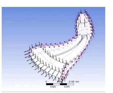
With the applied boundary condition, we get following result for cavitation model at -2200 RPM and mass flow rate 35 kg/s. The blue color area in the plot shows that the absolute pressure is less than or equal to 3170 Pa (Pressure Saturation). The color other than blue shows the drop of pressure and reaching the vapor pressure on the impeller blades. This forms the cavitation and affects the performance of the centrifugal pump and it is noted from the above analysis that, cavitation is increasing with the increase of mass flow rate and rotating speed. From Rotational Periodicity, it is verified that the model is symmetrical with axis of rotation and no surfaces overlaps each other. Hence less chances of bleeding and leakage.
Fig -6: Cavitation Model of Impeller
Fig -7: Pressure Distribution Plot of Cavitation Model
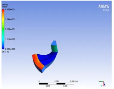
Fig -8: Velocity Distribution Plot of Single Vane of Impeller
Fig -9: Pressure Distribution of Single Vane of Impeller
7. CONCLUSIONS
CFD analysis was carried out at design and off design condition and results obtained are satisfactory. The Simulation was performed by using turbulent modeling tool standard k-Epsilon. Performance charts, cavitation analysis, pressure contours and velocity vector contour are obtained after analysis.
The mesh is generated successfully using ANSYS-CFX. The performance results are satisfactorily matching with test data, hence mesh quality is good.
After analysis the performance results shows that total static head is the function of the mass flow rate with constant operating speed.
[image:4.595.76.286.77.223.2] [image:4.595.339.530.295.444.2] [image:4.595.74.250.447.580.2]© 2017, IRJET | Impact Factor value: 5.181 | ISO 9001:2008 Certified Journal | Page 739
REFERENCES
[1] S.Rajendran and Dr.K.Purushothaman, “Analysis of a centrifugal pump impeller using ANSYS-CFX,” International Journal of Engineering Research & Technology, Vol. 1, Issue 3, 2012.
[2] S R Shah, S V Jain and V J Lakhera, “CFD based flow analysis of centrifugal pump,” Proceedings of the 37th National & 4th International Conference on Fluid Mechanics and Fluid Power, IIT Madras, Chennai, 2010.
[3] P.Usha Shri ans C.Syamsundar, “Computational analysis on performance of a centrifugal pump impeller,” Proceedings of the 37th National & 4th International Conference on Fluid Mechanics and Fluid Power, IIT Madras, Chennai, 2010.
[4] E.C. Bacharoudis, A.E. Filios, M.D. Mentzos and D.P. Margaris, “Parametric Study of a Centrifugal Pump Impeller by Varying th e Outlet Blade Angle,” The Open Mechanical Engineering Journal, Vol. 2, Pg. 75-83, 2008.
[5] Marco Antonio Rodrigues Cunh and Helcio Francisco Villa Nova, “Cavitation modelling of a centrifugal pump impeller,” 22nd International Congress of Mechanical Engineering, Ribeirao Petro, Sao Paulo, Brazil, 2013.
[6] Mohammed Khudhair Abbas, “Cavitation in centrifugal pumps,” Diyala Journal of Engineering Sciences, Pg. 170-180, 2010.
![Table -1: Design Specification for Impeller [2]](https://thumb-us.123doks.com/thumbv2/123dok_us/8151071.802605/2.595.310.555.435.694/table-design-specification-for-impeller.webp)