© 2016, IRJET | Impact Factor value: 4.45 | ISO 9001:2008 Certified Journal
| Page 1080
THD COMPARISON OF F1 AND F2 FAILURES OF MLI USING AMPLITUDE
LIMITED MODULATION TECHNIQUE
S.Santhalakshmy
1, V.Thebinaa
2, D.Muruganandhan
31
Assisstant professor, Department of Electrical and Electronics Engineering, Manakula Vinayagar Institute of
Technology, Pudhucherry, India.
2
Assisstant professor, Department of Electrical and Electronics Engineering, Manakula Vinayagar Institute of
Technology, Pudhucherry, India.
3
Assisstant professor, Department of Electrical and Electronics Engineering, Manakula Vinayagar Institute of
Technology, Pudhucherry, India
---***---Abstract -
This paper focuses on the fault-tolerancepotential of multilevel inverter with redundant switching states of the cascaded multilevel inverter. The failure situations of the multilevel inverters are classified into two types according to the relationship between output voltage levels and switching states. The gate signals can be reconfigured according to the failure modes when some of the power devices fail. The reconfiguration method is discussed for phase disposition PWM strategy (PDPWM) in the paper and it can be extended for other carrier-based PWM strategies easily. Balanced line-to-line voltage will be achieved with the proposed method when device failure occurs. Furthermore, the circuit structures can be the same as the general ones and the voltage stress of the devices does not increase. Simulation results are included in the paper to verify the proposed method.
Key Words: Amplitude limited modulation method (PWM) strategies, fault-tolerance, multilevel inverters, Total Harmonic Distortion (THD).
1.
INTRODUCTION
For high power applications, multilevel inverter structures have the particular advantages of operation at high dc-bus voltages, achieved by connecting switching devices in series, and reduction in output voltage harmonics, achieved by switching between multiple voltage levels. How-ever with this increase in switch numbers, failure probability increases, and hence reliability decreases. The study of fault modes and suitable protection strategies to mitigate this issue is important but complex due to the high integration and interaction of the system components.
Studies on multilevel inverters have focuses on fault-tolerance from different perspectives. The topology proposed in provides redundancy ability at all voltage levels, which is realized by using a proper combination of switching states. When a part of the circuit fails, the main function of the circuit can be realized by using inherent redundant resources. The cascaded H-bridge multilevel inverter is studied. The damaged power cell is bypassed and the space vector PWM pattern is adjusted such that the inverter is able to continue to produce a three-phase balanced line-to-line voltage. When a fault occurs, the faulted device is bypassed
by switching on the additional SCRs in parallel with the power semiconductors.
In this paper, multilevel inverters with redundant switching states as shown in Fig. 1 are studied. The multilevel inverter considered is the five-level cascaded inverter. When a power device failure occurs, the gate signals are reconfigured and balanced line-to-line voltage. will be achieved, without increasing the voltage stress of the devices.
Fig. 1 Five-level topologies (one leg circuit) Cascaded converter
To begin the analysis, the failure situations are classified into two types according to their relationship between output levels and switching states, and some fault diagnosis issues are described briefly. Next, the reconfigurations of the gate signals are presented for the phase disposition PWM strategy (PDPWM). Finally, simulation and experimental results are included in the paper to verify the proposed method.
2. FAULT ANALYSIS FOR THE MULTILEVEL
INVERTERS
[image:1.595.353.530.350.485.2]© 2016, IRJET | Impact Factor value: 4.45 | ISO 9001:2008 Certified Journal
| Page 1081
2.1
CLASSIFICATION OF SWITCHING DEVICE FAILURE
IN THE MULTILEVEL INVERTERS
It is obvious that when a power switch short circuit failure occurs, the source or capacitors will discharge through a conducting switch pair, if no protective action is taken. Hence the counterpart of the failed switch must be turned off quickly and properly to avoid system collapse due to a sharp current surge.
On the other hand, a power switch open circuit failure will cause a hazard by attempting to interrupt the load current, if no protective action is taken. Hence the counterpart of the failed switch must be turned on quickly and properly.
According to the switching states, these failure situations can be classified into two types as follows
1) Failure Type 1 (F1).
When a positive switch fails open circuit, the negative switch in the same pair must be turned on; when a negative switch fails short circuit, the positive switch in the same pair must be turned off. These two failure states lead to the loss of the highest output level, i.e.2VDC in the five-level phase leg.
2) Failure Type 2 (F2).
When a positive switch fails short circuit, the negative switch in the same pair must be turned off; when a negative switch fails open circuit, the positive switch in the same pair must be turned on. These two failure states lead to the loss of the lowest output level, i.e.-2VDC in the five-level phase leg.
Using switching state redundancy, the output voltage at intermediate levels can still be obtained by choosing the proper switching states when a single switch device fails.
TABLE 1: Range Of Phase Voltage Levels According To Switch Device Failure Types
FAILURE SITUATIONS OUTPUT VOLTAGE
RANGE Positive switch open
circuit -2V
DC ~ VDC
Positive switch short
circuit -V
DC ~ 2VDC
Negative switch open
circuit -V
DC ~ 2VDC
Negative switch short
circuit -2V
DC ~ VDC
Table 1 shows the range of phase voltage levels multilevel inverters can achieve when a single switch device fails according to above failure types. Hence the phase voltage can be achieved at a reduced modulation index by modifying the reference of the fault pair to satisfy the effective region illustrated in Table II. In principle, a large number of modification methods for the fault switch reference are feasible as long as the fault switch reference enables the output voltage to be in the effective region.
2.2 FAULT DIAGNOSIS FOR THE MULTILEVEL
INVERTERS:
Before the circuit reconfiguration is implemented according to the failure types, fault detection is essential. Many fault detection methods have been discussed over the last few years. Resistor sensing, current transformer and VCE sensing are the more popular schemes.VCE sensing method is adapted in this paper due to its simplicity and low cost. According to an IGBT’s characteristic, when the short circuit occurs, the voltage across the device should be in the low on state. And when the open circuit occurs, a permanent blocking will be caused. This fault could be recognized by
measuring the current cross the IGBTs. Thus the V
CEsensing method can give clear fault type indications.
3.
RECONFIGURATION
OF
THE
PDPWM
MODULATION STRATEGY:
Carrier based modulation techniques are widely used in multilevel converters, since compared to space vector PWM strategy, this PWM strategy has the distinct advantage of ease of implementation. The phase disposition PWM strategy is considered in this paper.
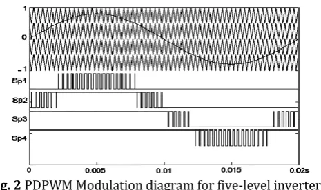
[image:2.595.317.550.482.620.2]For multilevel inverters, it is generally accepted that phase disposition PWM gives rise to the lowest harmonic distortion. The PDPWM modulation diagram for a five-level inverter is illustrated in Fig. 2. The four triangular carrier waveforms are arranged to fully occupy contiguous bands and a single reference waveform is compared against these carriers to determine how the devices should be controlled.
Fig. 2 PDPWM Modulation diagram for five-level inverters
For the topologies in Fig. 1, the four pulse signals shown in Fig. 2 can be distributed to the four switch pairs in any sequence. This characteristic is of great benefit to the reconfiguration of the modulation strategy.
3.1
AMPLITUDE-LIMITED
MODULATION
METHOD FOR F1 FAILURE TYPE:
© 2016, IRJET | Impact Factor value: 4.45 | ISO 9001:2008 Certified Journal
| Page 1082
switch pairs continue operation. To deal with this case, [image:3.595.310.556.75.252.2]Amplitude-Limited Modulation Method is considered as follows
Fig. 3 Equivalent modulation diagram for F1 Failure Mode
3.2
AMPLITUDE-LIMITED
MODULATION
METHOD FOR F2 FAILURE TYPE:
When an F2 fault occurs, the effective reference and the modulation process become that illustrated in Fig. 4. The bottom (faulty) switch pair ceases operation while the healthy switch pairs continue operation. To deal with this case, Amplitude-Limited Modulation Method is considered as follows
Fig 4 Equivalent Modulation Diagram For F2 Failure Mode
4. SIMULATIONS AND RESULTS:
4.1 For Normal Operation:
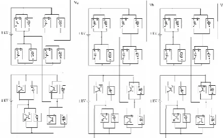
[image:3.595.46.277.140.276.2]The circuit for two bridge configuration of multilevel inverter and modulation diagram for Phase A of PD PWM for normal operation is shown in fig 5 and fig 6 respectively.
[image:3.595.312.557.316.432.2]Fig. 5 Circuit For Two Bridge Five-Level Inverter
Fig. 6 Modulation Diagram For Phase A Of PDPWM For Normal Operation
The phase output voltage waveform and line-line output voltage waveform of PD PWM for normal operation is shown in fig 7 and 8 respectively.
Fig. 7 Phase Output Voltage Waveform Of PDPWM For Normal Operation
Fig. 8 Line-Line Output Voltage Waveform Of PDPWM For Normal Operation
4.2 For F1 Failure Type
: [image:3.595.62.273.389.505.2] [image:3.595.308.564.466.590.2] [image:3.595.50.271.592.728.2]© 2016, IRJET | Impact Factor value: 4.45 | ISO 9001:2008 Certified Journal
| Page 1083
[image:4.595.302.559.58.361.2]Fig. 9 Modulation Diagram For Phase A Of PDPWM For F1
Fig. 10 Phase Output Voltage Waveform Of PDPWM For F1
The below table 2 shows the comparison between normal operation and F1 fault for amplitude-limited modulation method (PDPWM).
Table 2: Comparison between Normal Operation And F1 Fault
4.3 For F2 Failure Type
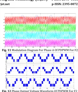
:The modulation diagram of Phase A and phase output voltage waveform of PDPWM for F2 failure type is shown in fig 11 and fig 12 respectively.
Fig. 11 Modulation Diagram For Phase A Of PDPWM For F2
Fig. 12 Phase Output Voltage Waveform Of PDPWM For F2
The below table 3 shows the comparison between normal operation and F2 fault for amplitude-limited modulation method (PDPWM).
Table 3 Comparison Between Normal Operation And F2 Fault
5. CONCLUSIONS
The theoretical approaches is developed for the fault tolerant operation in H-bridge multilevel inverter of a 5-level. The obtained results show that the balanced output for different unbalanced topologies of the multilevel inverter is possible. Additionally, the optimization of the sequences of the voltage states enables a better distribution of the firing pulses in the cells of the inverter with bypassed cells.
[image:4.595.36.289.98.394.2]© 2016, IRJET | Impact Factor value: 4.45 | ISO 9001:2008 Certified Journal
| Page 1084
REFERENCES
[1] B. P. McGrath and D. G. Holmes, “Multicarrier PWM strategies for multilevel inverters,” IEEE Trans. Ind. Electron. , vol. 49, no. 4, pp.858–867, Aug. 2002.
[2] J. S. Lai and F. Z. Peng, “Multilevel converters—A new breed of power converters,” IEEE Trans. Ind. Appl., vol. 32, no. 3, pp. 509–517, May/Jun. 1996.
[3] F. Z. Peng, “A generalized multilevel inverter topology with self voltage balancing,” IEEE Trans. Ind. Appl., vol. 37, no. 2, pp.611–618, Mar./Apr. 2001.
[4] Y. S. Kim, B. S. Seo, and D. S. Hyun, “A novel structure of multilevel high voltage source inverter,” in Proc. IEEE TENCON’93 Conf., Beijing, China, Oct. 1993, pp.503–508.
[5] C. Turpin, P. Baudesson, F. Richardeau, F. Forest, and T. A. Meynard, “Fault management of multicell converters” IEEE Trans. Ind. Electron., vol. 49, no. 5, pp. 988–997, Oct. 2002.
[6] A. L. Chen, L. Hu, L. F. Chen, Y. Deng, and X. N. He, “A multilevel converter topology with fault tolerant ability,” IEEE Trans. Power Electron., vol. 20, no. 2, pp. 405–415, Mar. 2005.
[7] S. M. Wei, B. Wu, F. H. Li, and X. D. Sun, “Control method for cascaded H-bridge multilevel inverter with faulty power cells,” in Proc.IEEE Appl. Power Electron. Conf., Miami, FL, Feb. 2003, vol. 1, pp.261–267.
[8] X.Kou,K.A.Corzine, andY. L. Familiant, “Aunique fault-tolerant design for flying capacitor multilevel inverter,” IEEE Trans. Power Electron., vol. 19, no. 4, pp. 979–987, Jul. 2004.
[9] D. G. Holmes and T. A. Lipo, Pulse width modulation for power converters—Principles and practice. Piscataway, NJ: The IEEE, Inc.,Oct. 2003.