Audio Transmission Using Li-Fi Technology
M. Sharmila
1, M. Shrin Shifana
2, V. Theebica
3, V. Sangeethapriya
4, Mrs. M. Prathibha
51234Student, Dept of ECE, Panimalar Engineering College, Chennai 5Assistant Professor, Dept of ECE, Panimalar Engineering College, Chennai
---***---
Abstract -
In a world of wireless technology, the number ofdevices accessing the internet is growing every second. Most of the devices use wireless communication to access internet for sharing data, this has unfortunately led to an increase in network complexity, shortage of wireless radio bandwidth and an increased risk of interference of radio frequencies. Li-Fi technology is used to transmit the data using Visible light communication by using light-emitting diodes.Signals are transmitted from one system to another by using LED as a Li-Fi transmitter and photodiode as a Li-Li-Fi receiver. This is a much more secure method of transmission compared to existing technologies.Noticeable Light Communication (VLC) has increased extraordinary enthusiasm for the most recent decade because of the quick improvements in Light Emitting Diodes (LEDs) manufacture. Adequacy, durable and long life expectancy of LEDs make them a promising private lighting hardware and also an option shabby and quick information exchange gear.Also the data transmission rate is very high around few Gbps. This project describes and implements the design of Li-Fi audio transmission system.
Key Words: VLC, Li-Fi, LED, PIC Microcontroller, APR
1. INTRODUCTION
In today world, communication between the devices are much common. Radio wave spectrum is very small part of spectrum available for communication. Wi-Fi and Bluetooth are currently the two prominent short range wireless technologies But with increase in advanced technology and number of user the network becomes overloaded which results in failure to provide high data rate. Visible light acts as rival to the present wireless radio frequency communication by achieving larger bandwidth and high data rate. Because with larger frequency spectrum it is possible to provide a larger portion of the bandwidth to each user to transfer information. A switching LED can be improbably causing annoyance, but data can therefore be encoded in the light by varying the rate at the LEDs switch on and off to provide various strings of 1’s and 0’s.
The use of fast pulses of light to transfer data without physical connection such method is called as Visible light communication (VLC).The LEDs can be switched ON and OFF very fast which is not noticeable by human eye thus the light source appear to be constantly on.When these signals transmitted to the receiver via the wireless channel, the photo diode will convert these optical signals to electrical signals and the original information will be recovered..
2. EXISTING SYSTEM
The existing Wireless communication makes use of electromagnetic waves for communication system. For instance, the deployment of Wi-Fi obviously brings several important benefits. Because it is very convenient that numbers of equipment connect to each other using wireless networks. Home-based Wi-Fi enabled device helps you to connect PC, game console or laptop. There are no boundaries if you are using Wi-Fi, you can move from one room to another or even away from home you have the liberty to access internet within the range of radial distance. Wi-Fi hotspots concept is getting popularity among business communities and mobile workers. For this reason ISPs are consolidating Wi-Fi switches to numerous spots for the scope of wide range.
3. IMPLEMENTATION
On the basis of visible light communication technology, the advanced technology called Li-Fi provide dual function of visible light LED for illumination and data transmission. Li-Fi is very latest version of Wi-Fi which uses visible light in place of radio waves. Hence, visible light data transmission rate have higher speed than other broadband. It overcome the problem related with Wi-Fi, because Li-Fi has wider network area so traffic handling capacity improved and it is cheaper than Wi-Fi.
The VLC system is compared with other wireless communication system that are in current use like LAN and Wi-Fi. LAN is available in very short range and it is not mobile. And Wi-Fi has low traffic handling capacity as number of user increases Wi-Fi becomes unable to achieve user’s need. Li-Fi offers significant capability to resolve this problem compared with Wi-Fi. It transmits data by switching LEDs on and off rapidly by changing light intensity which is not detected by human eye.
The data transmission rate is about 10Gbps by using white bright LED.The indoor visible light communication uses visible light spectrum to provide high rate data transmission which at the same time used as energy efficient illumination. In this way, the idea of the dual function of communication and illumination offers opportunity for efficient cost reduction and carbon footprint reductions.
4. PROPOSED SYSTEM
consists of an APR, Li-Fi transmitting module,MIC and the receiver section consists of a Li-Fi receiving module, PIC microcontroller, an amplifier, speaker and a transformer.
1. Transmitter Section
In the process of voice communication through the visible light on the transmitter side, voice is used as the input signal. This signal is converted to an electrical signal through a microphone. The transmitted data will be digitized then the digital signal drives the LED by using on-off-keying (OOK) modulation. LED, turning led ON for ones and OFF for zeros. Hence, the transmission data rate has to be so high that it eliminates the flicker and perceive as a constant light source to human eye. LED, turning led ON for ones and OFF for zeros.
Fig-1: Transmitter Block Diagram
1.1Voice Record And Playback Module:
1.1.1 General Description
WTV-SR is one of the members of recording serial products. WTV-SR module can record as well as fixed voice playback, recording content uploaded and a variety of control modes can be chosen. With the ace chip and module SPI-FLASH, it has an awesome favorable position in the span time of recording and cost execution.
1.1.2 Product Description
WTV-SR is provided with mp3 mode, Key control one by one, parallel interface, one-line serial interface, three-line serial interface. Therefore, WTV-SR module is suit for many occasions. It can be changed different control modes by setting I/O, which on the bottom of WTV-SR. It gives a Flexible power supply by eithersupply module or supply solution, so it is a effective recording solution.
The recorded voice can be uploaded to the system. It also supports download voice from PC and play recorded voice with high qualityIt can record up to 252 segment voice
(including fixed voice) and recording time up to 1600 seconds. It supports audio recording at 10 KHz or 14 KHz sample rate.
Fig-2: Playback Module
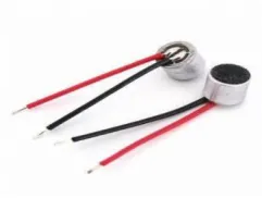
1.2Microphone:
In the process of voice communication through the visible light on the transmitter side voice is used as the input signal. This signal is converted to an electrical signal through a condenser or microphone.
Fig-3: Microphone
1.3 Li-Fi Transmitter:
The data whose has to transmit given from the playback module to the modulator circuit.The information is modulated to bits of 1’s and 0’s using On-Off Keying modulation .Light is used as a carrier signal.The modulated signal is amplified by Audio Amplifier. The data’s of 1’s and 0’s comes out from LED which on for ones and off for zeros.
2. Receiver Section
[image:2.595.329.559.143.311.2] [image:2.595.39.278.293.458.2] [image:2.595.373.494.434.525.2]
be amplified by Audio amplifier then using relay proper information (audio) comes out from the speaker.
Fig-4: Receiver Block Diagram
2.1 Li-Fi Receiver:
The data of ones and zeros from the LED source absorbed by the photo detector and equivalent electrical signal is produced. This signal is demodulated and then amplified by audio amplifier. Light intensity is absorbed by LDR .Based on the intensity of the light, microcontroller detects the error and minimizes using PWM error minimization technique. The error controlled audio signal comes out using speaker.
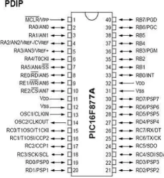
2.2 PIC Micro Controller:
The PIC16F877A is a CMOS flash-based 8-bit microcontroller, which has operating frequency of 20 MHz. It takes 200 ns to execute an instruction cycle. In our project we have used a 40 pin PIC16F877A.
Its main function is to control the voice recorder. It serially send the recorded audio file from voice recorder to the transmitting module. For that it uses RS-232 device which helps the microcontroller to send the data serially. In receiver section the PIC takes the audio from the receiving module and transmits to the amplifier.
Fig-5: Pin Diagram Of PIC16F877A
2.3 Audio Amplifier:
Audio amplifier can amplify sound that is given from Microphone. This circuit can be used as “Small mic and loudspeaker system” for a small space like a room. This circuit can also be used in many applications like portable music players, intercoms, radio amplifiers, TV sound systems, Ultrasonic drivers etc. It can also be used as sound sensor for microcontrollers. It is inexpensive, low power operated and only need few components to work. This circuit depends on LM386 IC to increase sound.
[image:3.595.44.286.120.275.2]
LM386 is a low voltage sound intensifier and oftentimes utilized as a part of battery controlled music gadgets like radios, guitars, toys and so forth. The pick up go is20 to 200, pick up is inside set to 20 (without utilizing outside segment) yet can be expanded to 200 by utilizing resistor and capacitor between PIN 1 and 8, or just with a capacitor. Voltage pick up essentially implies that Voltage out is 200 times the Voltage IN. LM386 has a wide supply voltage go 4-12v. The following is the Pin outline of LM386.
Fig-6: LM386 Audio Amplifier
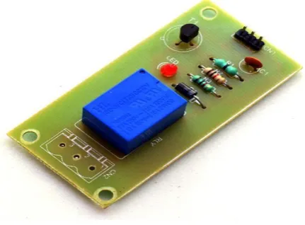
2.4 Single Relay Board
2.4.1 General Description
Relays are simple switches which are operated both electrically and mechanically. Relays consist of a n electromagnet and also a set of contacts. The switching mechanism is carried out with the help of the electromagnet. The main operation of a relay comes in places where only a low-power signal can be used to control a circuit.
It is also used in places where only one signal can be used to control a lot of circuits. They were used to switch the signal coming from one source to another destination. The high end applications of relays require high power to be driven by electric motors and so on. Such relays are called contactors.
2.4.2 Product Description
[image:3.595.341.518.346.488.2] [image:3.595.91.252.591.765.2]disconnection circuit. A transfer is amassed with that circuit. The driver circuit contains transistors for exchanging activities. The transistor is use for exchanging the transfer.
Fig-7: Single relay board
An isolation circuit prevents reverse voltage from the relay which protects the controller and transistor from damage. The input pulse for switching the transistor is given from the microcontroller unit. It is used for switching of a single device.
2.5 LDR Sensor
2.5.1 General Description:
A photo resistor (or light-dependent resistor, LDR, or photo-conductive cell) is a light-controlled variable resistor. The resistance of a photo resistor decreases with increasing incident light intensity; in other words, it exhibits photoconductivity. A photo resistor can be applied in light-sensitive detector circuits, and light-activated and dark-activated switching circuits.
2.5.2 Product Description:
LDR is used to measure light intensity . It uses pic microcontroller 16F877A and LCD to display light intensity. However, microcontroller cannot detect the change in resistance directly. LDR has to be given biasing voltage along with pull up or pull down resistance so that change in resistance is converted into change in voltage.
The change in analog voltage is converted into digital equivalent using ADC and this digital value is read by microcontroller.
Fig-8: LDR Sensor
2.6 Speaker
In this project we use Speaker which converts Electrical or Analog signals to the audible form to reach the Receptor. It converts the sound signal with the help of Electromagnets present in the Speaker. Hence the Receptor Receive the input has been transmitted from the transmitter.
5. RESULT
[image:4.595.44.260.140.299.2]The audio files were recorded in APR. When any of the APR switch was pressed the LED started blinking. This blinking of LED shows that the audio file is getting transmitted. Now, when the receiver module is brought in line of sight of the transmitter, photodiode receives the audio files and sends to the speaker with the help of PIC microcontroller. The scope of sound transmission was tried to be around 15-20 m. This is so on the grounds that after this separation the light gets scattered and couldn't fall appropriately on the photodiode. The beneath table is an examination between Wi-Fi and Li-Fi.
Table -1: Wi-Fi vs Li-Fi
Feature Wi-Fi Li-Fi
Full Form Transmit data
using radio waves
Transmit data using light
Interference Will have Does not have
Coverage
distance About 32m About 10 m
Data density Low High
Privacy RF signal cannot blocked by walls Light is blocked by walls
6. FUTURE SCOPE
Li-Fi is an emerging technology and hence it has vast potential. A lot of research can be conducted in this field. Already, a lot of scientists are involved in extensive research in this field. This technology, pioneered by Harald Haas, can become one of the major technologies in the near future. If this technology can be used efficiently, we might soon have something of the kind of WI-FI hotspots wherever a light bulb is available. As the amount of available bandwidth is limited, the airwaves are becoming increasingly clogged, making it more and more difficult to get a reliable, high-speed signal. The Li-Fi technology can solve this crisis.
[image:4.595.302.567.364.490.2]to 5 gigabits per second, ten times the current maximum wireless transfer rate, at one-tenth the cost.
Researchers chose the 57–64 GHz unlicensed frequency band since the millimetre-wave range of the spectrum allowed high component on-chip integration as well as the integration of very small high gain arrays. The available 7 GHz of spectrum results in very high data rates, up to 5 gigabits per second to users within an indoor environment, usually within a range of 10 meters . Some press reports called this "Gi-Fi". It was developed by Melbourne University-based laboratories of NICTA (National ICT Australia .
7. CONCLUSION
This technology is still under research and surely it will be a breakthrough in communication. It assures data speed of100gbps which is entirely greater than radio waves. The scope of this Li-Fi technology is ultimately greater. As Li-Fi provides secured, low cost, easy data transmission and provides reliable communication, It can be used in industrial, medical, military applications. Li-Fi is still in its beginning stages, but improvements are being made rapidly, and soon this technology will be able to be used in our daily lives. It is intended that this research will provide the starting steps for further study .In spite of the research problems it is our belief that the VLC system will become one of the most promising technologies for the future generation in optical wireless communication.
8. REFERENCES
[1] Punith P. Salian, Sachidananda Prabhu, Preetham Amin, Sumanth K.Naik, Dr. M.K. Parashuram,”Visible Light Communication”,Texas Instruments India Educators' Conference, 978-0-7695-5146-3/13 $26.00 © 2013 IEEE
[2] Zashi P. Choudhari,Satish R. Devane,” High sensitivity universal Lifi receiver for enhance data communication” 2016 Online International Conference on Green Engineering and Technologies (IC-GET) 978-1-5090-4556-3/16/$31.00 ©2016 IEEE
[3] Luis Bica Oliveira, Nuno Paulino, João P.Oliveira,Rui Santos, Nuno Pereira, João Goes, Undergraduate Electronics Projects Based on the Design of an Optical Wireless Audio Transmission System 0018-9359 © 2016 IEEE.
[4] Mohit Sanjeev Kumar, Gujar Shrikant, Velankar Arun Chavan”Realtime audio streaming using visible light communication ” Inventive Computation Technologies (ICICT), International Conference 16620571@IEEE
[5] D. Tsonev, S. Videv and H. Haas "Light Fidelity (Li-Fi): Towards All-Optical Networking", Institute for Digital Communications, Li-Fi R&D Centre, The University of Edinburgh, EH9 3JL, Edinburgh, UK.
[6] T.Komine and M.Nakagawa, ”Fundamental analysis for visible light communication systems using LED Lights,” IEEE Trans. Consumer Electronics, vol. 59, no.1, Feb, 2004.
[7] M.Kavehrad, “Sustainable Energy Efficient Wireless Applications Using Light,” IEEE Commun. Mag., vol. 48, no. 12, Dec. 2010, pp. 66- 73.