http://dx.doi.org/10.4236/ojmsi.2015.32004
How to cite this paper: Lee, J.K., Park, G.O., Kim, K.K., Huh, W.S. and Sohn, K.Y. (2015) Integrated Testing Environment of Instructor Station for SMART Simulator. Open Journal of Modelling and Simulation, 3, 33-40.
http://dx.doi.org/10.4236/ojmsi.2015.32004
Integrated Testing Environment of
Instructor Station for SMART Simulator
Joon Ku Lee1, Geun Ok Park1, Keung Koo Kim1, Woo Seok Huh2, Kwang Young Sohn2* 1Korea Atomic Energy Research Institute, Daejeon City, Korea
2MIRAE Engineering Co., Ltd., Daejon City, Korea
Email: *[email protected]
Received 15 February 2015; accepted 20 March 2015; published 23 March 2015
Copyright © 2015 by authors and Scientific Research Publishing Inc.
This work is licensed under the Creative Commons Attribution International License (CC BY). http://creativecommons.org/licenses/by/4.0/
Abstract
SMART is the reactor that has been researched for many years by KAERI in order to provide the small-mid scale of power for typically seawater desalination. Now Korea Atomic Energy Research Institute (KAERI) has issued Standard Safety Analysis Report (SSAR) and acquired Standard De-sign Approval (SDA) for SMART. In order to conduct the deDe-sign verification and validation for li-cense, the integrated simulation test environment that is composed of 1) the system specific si-mulation codes formerly developed in the name of Nuclear Plant Analyzer (NPA) including NSSS and BOP simulation, 2) Instructor Station (IS), 3) Supervisory Control and Data Acquisition (SCADA), 4) operator and instructor Human Machine Interface (HMI), and 5) soft-controller has been con-sidered as an important area for operator training and system validation. These sub-components has been designed and implemented for verifying and validating the SMART design and training of operators and for generating the backup data for licensing. This paper introduces the structure of integrated simulation test environment for SMART, explains the efforts to assist system-specific simulation code interface, and also addresses the effort for implementing and optimizing the test environment by maintaining its own simulation functionality and performance in order to review the simulation results efficiently.
Keywords
System-Integrated Modular Advanced Reactor (SMART), Instructor Station (IS), Nuclear Plant Analyzer (NPA), Software Development Life Cycle (SDLC)
1. Introduction
SMART technology is the sensible mixture of innovative concepts and conventional technologies to improve the
level of safety, reliability and economy [1]. Although it is an unprecedented design without operating expe-riences and references, it acquires the Standard Design Approval (SDA) and issues Standard Safety Analysis Report (SSAR). It means that the test environment for the verification and validation of SMART design com-mensurate with system behavior validation, operator training and support for further optimization is required [2]. This Nuclear Plant Analyzer (NPA) has been developed for verifying the behavior of NSSS and BOP system. By extending this research, KAERI now is developing a full scope simulator, which is supported by the Inte-grated Test Environment (ITE) for SMART reactor, which is composed of system specific simulation codes, In-structor Station, and MMI (Man-Machine Interface) displays for operator’s interfaces.
2. Main Control Room (MCR) Test Facility
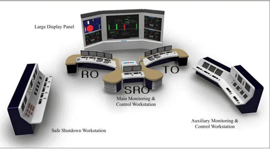
The digitalized MCR for ITE that is very similar to Figure 1 is composed of the following segments: • A Large Display Panel (LDP);
• A workstation for a Reactor Operator (RO); • A workstation for a Turbine Operator (TO); • A workstation for a Supervisory RO (SRO); • A workstation for safety shutdown;
• An auxiliary workstation.
Operator’s actions in the MCR are accomplished through digital interface means such as a LDP, Flat Panel Displays (FPD) and soft-controllers (SC). The LDP is to provide overall and key information to the operators in the MCR so that operator and/or operator could commonly understand the status of SMART operations through them.
The information on the LDP should be recognized by the operators as quickly and clearly as possible. Para-meters on a center panel of the LDP are fixed to encompass all the key and overall information of the SMART. Four wing panels are variable to provide supporting information such as alarm lists, graphs, and detail displays. The operator can change display pages to be indicated on the wing panels. The FPD is to provide detail informa-tion down to component levels. The operators have to navigate display pages on the FPD in order to get detail hierarchically deployed information of SMART operations. The SC is to provide touch-sensitive interfaces on the FPD to control components such as pumps, valves, motors and fans. The Man Machine Interface System (MMIS) includes the following systems:
Safe Shutdown Workstation
Auxiliary Monitoring & Control Workstation Main Monitoring &
[image:2.595.92.535.460.709.2]Control Workstation Large Display Panel
• Information Processing System (IPS); • Alarm and Indication System (AIS); • Post-Accident Monitoring System (PAMS);
• Inadequate Core Cooling Monitoring System (ICCMS); • Severe Accident Monitoring System (SAMS);
• Soft controller for safety and non-safety.
3. The Structure of Integrated Simulation Test Environment
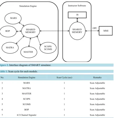
3.1. The Implementation of Instructor Station (IS)IS is established in the server platform based on the 3 Key Master environment on which a lot of system specific simulation code is running. Also it provides a mechanism to share the simulation value among the system spe-cific simulation codes. Figure 2 and Table 1show the functional configuration of IS and the information for each system specific simulation model. Instructor Station is communicating with SCADA server for exchanging the simulation data, and hand switches in Safety Shutdown Control Panel (SSCP) bi-directionally in order to get the operator’s control input as diagrammed in Figure 3.
Simulation Engine Instructor Software
IS MARS
BOP
MATRA
MASTER
MMI OPC
SCOPS/ SCOMS SHARED
MEMORY MEMORY SHARED
[image:3.595.121.515.284.692.2]Figure 2.Interface diagram of SMART simulator.
Table 1. Scan cycle for each module.
No. Simulation Engine Scan Cycle (sec) Remarks
1 MARS 1 Scan Adjustable
2 MATRA 1 Scan Adjustable
3 MASTER 1 Scan Adjustable
4 SCOPS 1 Scan Adjustable
5 SCOMS 1 Scan Adjustable
6 BOP 1 Scan Adjustable
7 4/2 Channel Signaler 1 Scan Adjustable
Freeze
Speed N
MFDel N Run
Exit Reset
Snapshot N
Snapshot
Delete N Backtrack N
Backtime N
MFIn N
Figure 3.Functions in ınstructor station.
The scan cycle for each simulation engine is the same so that a couple of consideration for generating the con-sistent chronicle order of each interface variables is possible to get refined data. This is provided by software module for simulation test aid in ITE. Instructor Station provides the function for training and design verifica-tion as indicated in Figure 3 which includes the injection and deletion of malfunction, generation and deletion of snapshot and multiple functions for simulator operation. Based on the integrated simulation test environment, IS provides the various functional commands such as fast, backtrack, halt and rewind etc. with the support of 3 Key Master environment.
3.2. SCADA Implementation
SCADA server is a data archive that interface with IS directly through TCP/IP communication, and command-ing the simulation inputs and process inputs to respond to the request of operator’s GUI interfaces to display those values in LPD, IPS display, AIS display, PAM/ICCM display, and SC display. Thus it contains the huge on line and offline database, and communicating with IS and GUI bi-directionally through the OPC and TCP/IP con-nection optionally. Especially interface between SCADA and MMI systems uses the “lazy binding” to enhance the performance of simulator environment.
3.3. Operator’s HMI Implementation
All of data coming from and going to SCADA is going to be displayed in the operator’s GUIs. The GUI display page is mainly designed based on the Process and Instrumentation Diagram (P & ID) and user requirements. It is composed of IPS display, AIS display, PAM/ICCM displays for operator operation, Severe Accident Monitor (SAM) and Computerized Procedure System (CPS) in RO, AO and SRO console appropriately. Major compo-nents described in Section 2 are connected through the OPC and/or TCP/IP connection with interface systems [3].
4. Efforts for Simulation Integrity
4.1. Logical Fidelityoff-line format.
Inherently simulator is functioning based on the single source of process input neglecting the rest of 3 chan-nels of safety and the rest of 1 channel of non-safety system in SMART. To eliminate this limitation, SMART simulator dedicates 4 (safety), 2 (non-safety) channels signal generator, which is generating the variables neces-sary to simulate SMART, and unnecesneces-sary variables that have nothing to do with simulation itself temporarily [4].
4.2. Malfunction List
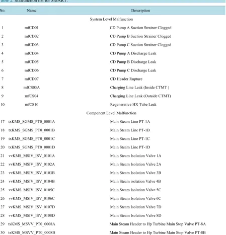
[image:5.595.90.540.250.718.2]SMART simulator is potentially is considering the 100% of thermal power output and its operation. The list of malfunction is derived from the analysis of DBE (Design Basis Event) for SMART as below 1 through 7. The malfunction is categorized into two categories of system level and component level malfunction. The major ac-cident type is like the followings which is a basis to draw the malfunction list. Table 2 shows some of those for examples.
Table 2. Malfunction list for SMART.
No. Name Description
System Level Malfunction
1 mfCD01 CD Pump A Suction Strainer Clogged
2 mfCD02 CD Pump B Suction Strainer Clogged
3 mfCD03 CD Pump C Suction Strainer Clogged
4 mfCD04 CD Pump A Discharge Leak
5 mfCD05 CD Pump B Discharge Leak
6 mfCD06 CD Pump C Discharge Leak
7 mfCD07 CD Header Rupture
8 mfCS03A Charging Line Leak (Inside CTMT )
9 mfCS04 Charging Line Leak (Outside CTMT)
10 mfCS10 Regenerative HX Tube Leak
Component Level Malfunction
17 txKMS_SGMS_PT0_0001A Main Steam Line PT-1A
18 txKMS_SGMS_PT0_0001B Main Steam Line PT-1B
19 txKMS_SGMS_PT0_0001C Main Steam Line PT-1C
20 txKMS_SGMS_PT0_0001D Main Steam Line PT-1D
21 vvKMS_MSIV_ISV_0101A Main Steam Isolation Valve 1A
22 vvKMS_MSIV_ISV_0102A Main Steam Isolation Valve 2A
23 vvKMS_MSIV_ISV_0103B Main Steam Isolation Valve 3B
24 vvKMS_MSIV_ISV_0104B Main Steam isolation Valve 4B
25 vvKMS_MSIV_ISV_0105C Main Steam Isolation Valve 5C
26 vvKMS_MSIV_ISV_0106C Main Steam Isolation Valve 6C
27 vvKMS_MSIV_ISV_0107D Main Steam Isolation Valve 7D
28 vvKMS_MSIV_ISV_0108D Main Steam Isolation Valve 8D
29 txKMS_MSVV_PT0_0008A Main Steam Header to Hp Turbine Main Stop Valve PT-8A
a) Heat removal by BOP (Balance of Plant); b) Fail or insufficient heat removal by BOP; c) Low reactor coolant flow;
d) Anomaly of reactivity and/or power; e) High reactor coolant inventory; f) Low reactor coolant inventory;
g) Radiation release form subsystem or components.
5. The Analysis for Simulation Results
5.1. Analysis of Simulation BehaviorIn the core of this integrated simulation test environment, integrator needs to produce the simulation results for the system-specific simulation engines described in Figure 2 andTable 1 in order for each simulation engine developer to compare the result to other engines’. For this, ITE for SMART simulator provide the following ca-pability:
1) Capability verifying simulation behavior by taking a look at all the interface variables, i.e. all modules in
Figure 2 andTable 1;
2) Capability to find out the divergence pattern.
The software supporting the efforts listed above 1) and 2 has been developed as separate software running in-dependently on IS, which is finally producing the excel sheet. Establishing this functionality in simulation envi-ronment, each system-specific engine designer is able to analyze the execution result of engines, which will be addressed below section.
5.2. The Pattern among Multi Engines
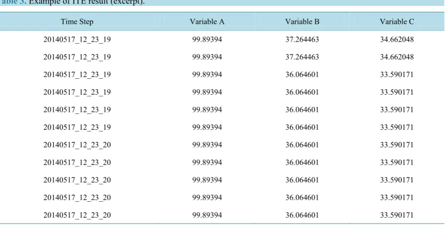
This is the sample of log checking the consistency of interface variables between MARS and MATRA chroni-cally. Table 3 is the sample (limited variables) of log checking the consistency of interface variables up to 700 point among the simulation module listed in Figure 2 running at the same time frame. As each scan time of a specific simulation engine is an important factor to generate the simulation test file, the highest resolution of time is selected to be a basis time line. The following is minimally a sample of those.
[image:6.595.91.540.491.718.2]InTable 3 that is a subset of ITE test results, time step and variable A, B and C means the selected time line and variables belong to specific simulation engine model respectively. It is transmitted to engineer or designer of specific simulator for further analysis as well as enhancement.
Table 3.Example of ITE result (excerpt).
Time Step Variable A Variable B Variable C
20140517_12_23_19 99.89394 37.264463 34.662048
20140517_12_23_19 99.89394 37.264463 34.662048
20140517_12_23_19 99.89394 36.064601 33.590171
20140517_12_23_19 99.89394 36.064601 33.590171
20140517_12_23_19 99.89394 36.064601 33.590171
20140517_12_23_19 99.89394 36.064601 33.590171
20140517_12_23_20 99.89394 36.064601 33.590171
20140517_12_23_20 99.89394 36.064601 33.590171
20140517_12_23_20 99.89394 36.064601 33.590171
20140517_12_23_20 99.89394 36.064601 33.590171
Table 4.Variable diverging more than +/− 10%.
Time Step MRC_CORE_LPL_A0001 (Previous) MRC_CORE_LPL_A0001 (Current)
20140522_15_55_58 69.041 133.54
5.3. The Detection of Divergence
The aid software for simulation result analysis is monitoring the each target variable in order to inspect one of the variables diverges into extreme abruptly which could cause the simulation engine to stop eventually. The major concern of this function is to find out the pattern of divergence in order engine developer to catch the cause and effect of the system.
The software module of ITE for detecting of variable divergence is monitoring the simulation variables diverg-ing from extreme to extreme that may cause the various event and simulation engine halt.
The amount of criteria of divergence variable is selected as +/− 10% of engineering range of each variable, and it is of course adjustable. Table 4 is the example of it.
The detection of events such as trip, halt, a various alarm is a useful aid for Instructor or operator is able to find out the causes and its effect during the simulation. For implementation of this purpose, detection agent ana-lyzes the event scenarios sampled from each simulation engine such as MARS, MATRA, MASTER and BOP model in order to provide the cause, variables contributing to various events, in order for simulation engine de-veloper to identify the causes and effects in system behavior for enhancement, which is being developed in up-coming phase.
6. Conclusions
The selective preparation of design document and its verification and validation based on IEEE code and stan-dard has been conducted for integrated testing environment for SMART simulator [5]-[7]. Establishing the inte-grated simulation environment, all the facilities in control room for real operation have been constructed to en-hance the physical fidelity of simulator, and develop the human interface with system simulation engines. By doing these, the design and operation of integrated testing environment for SMART simulator are the solid basis to verify the system design, train the operator, accumulate the quasi-operating data for analysis and licensing, and optimize SMART design based on all of these results. This is about the best effort to support the verification of simulation engine for SMART.
The simulation engines that are currently only simulating 100% of power operation will be expanded to cover up the various plant operation modes. The following technical issues should be resolved for complete simula-tion:
1) As the integrated simulation environment is evolved, the more delicate malfunction scenarios including in-itial condition and severe accident scenarios should be refined for design verification for SMART reactor;
2) Some of models in Balance of Plant (BOP) system are still under development. So, for completely inte-grated simulation environment for SMART, those simulation engines should be developed and inteinte-grated in ex-isting environment;
3) Also the method for generating the control rod position shall be devised and established in automatic and manual mode operation in order to verify the system behavior of SMART reactor too.
Acknowledgements
This work has been supported by the National Research Foundation of Korea (NRF) grant funded by the Korea government (MSIP) (No. 2012M2A8A4025979), and especially thank to Dr. J. K. Lee for supporting this work.
References
[1] Kim, K.K., Lee, W.J., Choi, S., Kim, H.R. and Ha, J.J. (2014) SMART: The First Licensed Advanced Integral Reactor.
Journal of Energy and Power Engineering, 8, 94-102.
[3] IEEE Std. 1023-2004 (2004) IEEE Guide to the Application of Human Factors Engineering to Systems, Equipment, and Facilities of Nuclear Power Generating Stations.
[4] ANSI/ANS-3.5-2009 (2009) Nuclear Power Plant Simulators for Use in Operator Training and Examination. [5] IEEE Std. 829-2008 (2008) Standard for Software and System Test Documentation.