© 2016, IRJET ISO 9001:2008 Certified Journal Page 1118
Optimized Design of Risering System for Casted Component by Using
Web Based Online Simulation E-Tool
Bhushan S. Kamble
1, Pradnyesh V. Kadam
2,
1
Assistant Professor, Dept. of Production Engg., KIT’s College of Engineering, Kolhapur, Maharashtra, India
2
PG student at Dept. of Production Engg., KIT’s College of Engineering, Kolhapur, Maharashtra, India
---***---Abstract -
The highest levels of casting yield should be attainable under mass scale production conditions, where there is wide opportunity for early experiment at the risk of defective castings and where gross weight can be reduced by progressive use of proper feeder head dimensions and use of different feedaids. Virtual Casting Simulation may used to assure sound quality of castings and yield optimization without carrying and charging out shop floor trails, it also helps to analyze and optimize feedability of a casting during predesign phase. A well-designed runner and gating system is very important to produce sound castings by providing a homogenous mould filling pattern. Defects such as Shrinkage porosity, Cold shuts, Misrun, and Gas porosity leads to heavy rejection upto 50% also. In order to improve the quality of the castings produced, the gating system was changed from the pre existing flat gate to a modified fed gate. Major parameters of a feeding system include are feeder modulus, neck dimension, feeder shape and location and use of different feed aids. Feeding systems are modified and simulated unless satisfactory results are obtained. Improved yield offers many benefits as reduced material cost, better process control. Hence significant improvement in the quality of casting by optimizing the location and design of feeder for minimal defects. Here a attempt is made to virtually simulate various feeding system designs in order to obtain optimum risering design by using e-foundry web tools.Key Words: Volumetric shrinkage; Casting simulation; Feeding system design; Riser modulus; Casting yield; and Optimum design.
1. INTRODUCTION
Manufacturing is the backbone of any industrialized nation. A basic Casting process is one of the earliest metal shaping and forming process. It means pouring molten metal into a refractory mold cavity and allows it to solidify. The solidified object is taken out from the mold either by breaking or taking the mold apart. The solidified object is called casting and the technique followed in method is known as casting process. In other word it’s a process wherein there is shortest distance between raw material and a finished good. A channel, gating system consists of pouring cup, runner, sprue, sprue well and ingate or gates, which is designed to guide liquid metal filling into the mould cavity.
Risers are used to compensate volumetric shrinkage caused during solidification of cast part.
It is difficult to avoid that many different defects occur in casting, such as blow holes, internal porosity and improper filling (11). Improving the cast quality becomes important role. Casting quality is depending on the proper gating/riser system design. Therefore there is a need for use of a computer-aided casting simulation tool with CAD, and optimize the results to ensure the quality of casting.
1.1
Gating System:
Fig-1. Principal features of a gating system. (a) Pouring basin, (b) Down Sprue (c) Runner, (d) Ingates
1.2 Objective of the Gating System:
The points, which enable a proper gating system, are: a) Clean molten metal
b) Smooth filling of the casting cavity c) Uniform filling of the casting cavity d) Complete filling of the casting cavity
© 2016, IRJET ISO 9001:2008 Certified Journal Page 1119 accompanied by appreciable volume contraction. The
purpose of a feeder head, therefore, is to provide a reservoir of liquid metal under a pressure head sufficient to maintain flow into the casting. Without feeding, the final casting will be subjected to shrinkage defects in the form of major internal cavities, voids, or surface sinks.
2. Feeder size volume:
The feeder shape and size required to balance the process of solidification shrinkage in the region of hot spot. The efficiency of the feeding is dependent on the feeder dimensions, its shape, and the type of feeder (either open , side or blind). When the single feeder is associated with various other castings, the feed metal volume condition is probable to fail for larger castings having thin cross sections. Methods for determining feeder head size must be based upon meeting the separate requirements for freezing time and feed volume, so ensuring directional solidification and a sound casting. Attempts should be made to keep minimum volume in gating system. As casting yield is given by
Casting yield= Wc /(Wc+ Wg)
Where Wc: Weight of casting and Wg: Weight of gating system
2.1 Feeder and casting modulus:
[image:2.595.330.535.125.310.2]To simplify the modulus calculation for more intricate castings, the principle of substitute bodies is employed, in which plain shapes are substituted for more elaborate shapes of equivalent modulus on the basis that two bodies of identical modulus will solidify in the same time.
Fig -2: Schematic of modulus of feeder and casting
3. Case study:
Details of casting are as follows i. Volume of casting=15649mm3 ii. Surface Area of casting =4454.8 mm2 iii. Material of casting=Aluminum Silicon alloy iv.Density of material Al 7178=2830kg/m3
v.Type of casting= Sand casting
[image:2.595.66.259.485.618.2]The 3D part modeling is made by usig CATIA v6 modeling software.
Fig -3: 3D Model Component under study for simulation
3.1. Design of feeder dimensions:
The modulus for a cylindrical riser is given by following equation.
Mriser=(Volume/Surface area) Mriser=[DH/(4H+2D)]
Where D is the riser diameter and H is the riser height. For calculating final riser dimensions made an assumption about the relationship between the riser height and diameter. In typical cases riser height is twice the diameter (H=2D) To ensure whether a riser can feed a casting or casting section? its maximum feeding volume should be checked against the casting or section volume.
Vmax= Vriser*[(14-S)/S]
Where Vmax is the maximum casting volume that can be fed, Vriser is the volume of the riser, and S is the specific shrinkage of the alloy in percent. The specific shrinkage “s” for Al-Si alloy is 3.8.
It is best to produce this part with a single top riser. To create directional solidification and prevent shrinkage, the riser should directly feed the hot spot location.
Mcasting=15649/4454.8=3.51
Mriser = 1.2Mcasting = 1.2(15649/4454.8) = 4.215 Assuming H/D = 1 or H=D--- assumption 4.215=[D2/(4D+2D)]
D=24.75 mm , approximately D= 25 mm H=25 mm
To confirm the riser is large enough to feed, Vmax =[π/4]D3*[(14-S)/S]
Vmax =[π/4]253*[(14-3.8)/3.8] =32940.21 mm3
© 2016, IRJET ISO 9001:2008 Certified Journal Page 1120
4. Casting simulation framework:
Fig - 4: online Simulation methodology
A free ware web resource provided by E-foundry IIT Bombay is used for carrying out simulation on website http://efoundry.iitb.ac.in. Following steps are carried out for simulation and feedability analysis.
1. Preparation of 3D Solid model a cast part using CATIA R16 and saving it as a .STL file format.
2. Browsing and uploading the casting 3D model .stl file on www.efoundry.iitb.ac.in
3. Selection of proper cast metal and method of casting as sand/Die casting.
4. After waiting till the simulation results are displayed this will identify hot spots location.
5. Hence as per hot spot location riser/feeder size and location is decided.
6. 3D Modeling the part with feeder and saving as a .STL file.
7. Revise Simulationn again and checking the location of hot spots.
8. If hot spots are not shifted inside feeders, repeated steps 4-6, till hotspot shifts to feeder and a optimized feeder size and location is decided which improves the casting yield.
4.1: Optimization of feeder dimension using
simulation with different trials with D and H as
variables:
[image:3.595.317.549.287.482.2]All dimensions are in mm
Table -1: Feeder and neak dimensions for different trials Riser
design Iteration
Riser Neak
D H D H
Trial 1 25 25 15 8
Trial 2 20 20 10 5
Trial 3 25 20 10 10
Trial 4 20 15 10 8
Trial 5 30 20 15 5
Trial 6 30 25 10 5
Table 2: casting yield for different iterations
Iteration V Modulus
M=V/A
Casting yield (%)
Remark
Trial 1
12265.63
4.2
56.1
Accepted
Trial 2
6280.00
3.3
71.4
x
Trial 3
9812.50
3.8
61.5
x
Trial 4
4710.00
3.0
76.9
x
Trial 5
14130.00
4.3
52.6
Accepted
Trial 6
17662.50
4.7
47.0
Accepted
4.2: Simulation using web E-Tool:
Fig - 6:
.stl file uploaded on efoundry.iitb.ac.in
[image:3.595.270.542.524.749.2]© 2016, IRJET ISO 9001:2008 Certified Journal Page 1121 Fig - 6: Simulation without Trial 1
Fig -7: Simulation with Trial 2
Fig -8: Simulation with Trial 3
Fig -9: Simulation with Trial 4
Fig -10: Simulation with Trial 5
© 2016, IRJET ISO 9001:2008 Certified Journal Page 1122
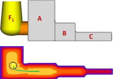
4.3: Discussions regarding simulation results:
By observing the color pattern of each simulation it is observed that blue color indicates early freezing regions in casting, and white yellow indicates hot spot. Different iterations of simulation are carried with different feeder diameters as shown in table 1. The trial 2, 3, and 4 are not accepted as hot spot is not completely shifted to riser. The trial 1, 5, and 6 are accepted as hot spot is completely shifted to riser. As per Table 2 , These three trials are further optimized by considering casting yield. The trial 1 with D=25mm and H=25 mm shows higher value of casting yield as 56.1%. Hence out of these 6 trials Trial 1 is selected as best riser shape and size.
3. CONCLUSIONS:
In this study, it was observed that a free of cost online virtual simulation tool available enables visualization of the progress of freezing inside a casting and identification of the last freezing regions or hot spots by identifying color coding. Casting simulation is a powerful tool to visualize progressive solidification of molten metal inside a mold cavity.
It helps in locating the riser at proper location to achieve directional solidification. By carrying out casting virtual simulation, material, time and money can be saved which are required in Foundry shop floor trials. From casting simulation casting products can be develop very fast and time required in development of cast parts will be less. Also Casting simulation helps to predict the defects and their locations.
REFERENCES
[1] Dr. B Ravi, (2007), Feedability Analysis and Optimisation Driven by Casting Simulation, Technical paper submitted to the Indian Foundry Journal
[2] P. Prabhakara Rao, G. Chakraverthi, A. C. S. Kumar, G. Srinivasa Rao, (2011)Modeling and Simulation of Solidification in Alloy Steel Sand Castings, Int. Journal of Thermal Technologies, Vol.1, No.1, Page. 110-116.
[3] C. M. Choudhari, B. E. Narkhede, S. K. Mahajan, (2012) “Finite Element Simulation of Temperature Distribution during Solidification in Cylindrical Sand Casting with Experimental Validation”, 4th International and 25th All India
[4] T. Ramu, M. L. S. Deva Kumar, B. K. C. Ganesh, Modeling,(2012), simulation and analysis in manufacturing of a flywheel casting by SG .iron, International Journal of Materials and Biomaterials Applications, 2(4): Page. 25-28.
[5] J. Padalkar, K. K. Dhumal, B. E. Narkhede, S. K. Mahajan, (2013) “Defect free casting by using simulation software, Applied Mechanics and Materials”, Trans Tech Publications, Switzerland, 313-314, 1130-113
[6] L.E.Smiley, D.C.Schmidt, (2013), “Computer design of feeding systems for iron castings or how to avoid years of problems with 20 minutes of analysis”, AFS Proceeding,
Americans foundry society, Schaumburg, IL,USA, Panel 13-1261,
[7] C. M. Choudhari, Nikhil S. Dalal, Akshay P. Ghude1, Pratik P. Sankhe, Ashutosh M.Dhotre,(2013), design and analysis of riser for sand casting, International Journal of Students Research in Technology & Management Vol 1(2), April 2013, Page.176-191
[8] A.K.Gajbhiye, C.M.Choudhari, D.N.Raut, B.E.Narkhede, B.M.Bhandarkar, (2014), Minimization of Shrinkage Porosity in A Sand Casting Process By Simulation In AUTOCAST-X Software with Experimental Validation by Destructive testing , International journal of Modern Engineering Research (IJMER), Vol.4 Issue 5.
[9] C. M. Choudhari, B. E. Narkhede, S. K. Mahajan,(2014), “Casting Design and Simulation of Cover Plate using AutoCAST-X Software for Defect Minimization with Experimental Validation”, 3rd International Conference on Materials Processing and Characterisation, Procedia Materials Science 6, Page. 786 – 797
[10] Harshil Bhatta, Rakesh Barota, Kamlesh Bhatta, Hardik Beravala ,Jay Shah, (2014 ), “Design Optimization of Feeding System and SolidificationSimulation for Cast Iron” ,Procedia Technology , 2nd International Conference on Innovations in Automation and Mechatronics Engineering, ICIAME 2014, Page.357 – 364
[11] Bhushan Shankar Kamble, (2016), “Analysis of Different Sand Casting Defects in a Medium Scale Foundry Industry - A Review”, International Journal of Innovative Research in Science, Engineering and Technology , Vol. 5, Issue 2, Page. 1281-1288
[12] Dr. Robert Tuttle, Simple riser design, Saginaw Valley State University University Center, MI
BIOGRAPHIES:
Bhushan Shankar Kamble Assistant Professor
KIT’s College of Engineering, Kolhapur Maharashtra.
Area of Interest: Material science casting and virtual simulation
Pradnyesh V. Kadam P.G Student
Dept. of Production Engineering KIT’s College of Engineering, Kolhapur Maharashtra.