GENERATING UML CLASS DIAGRAM FROM SOURCE CODES USING MULIT-THREADING TECHNIQUE
SAIF KHALID ABDULLAH
A dissertation submitted in partial fulfilment of the requirement for the award of the
Degree of Master of Computer Science (Software Engineering)
Faculty of Computer Science and Information Technology Universiti Tun Hussein Onn Malaysia
ABSTRACT
vi
ABSTRAK
TABLE OF CONTENTS
TITLE i
DECLARATION ii
DEDICATION iii
ACKNOWLEDGMENT iv
ABSTRACT v
ABSTRAK vi
TABLE OF CONTENTS vii
LIST OF FIGURES x
LIST OF TABLES xii
LIST OF APPENDICES xiii
CHAPTER 1 INTRODUCTION 1
1.1 Background of research 1
1.2 Research motivations 3
1.3 Objectives 4
1.4 Scope of research 4
1.5 Expected outcomes 5
1.6 Chapter summary 6
1.7 Dissertation outline 6
CHAPTER 2 LITERATURE REVIEW 8
2.1 Introduction 8
2.2 Reverse engineering derivatives 8
2.2.1 Reverse engineering 9
2.2.2 Restructuring 9
2.2.3 Reengineering 10
2.3 Reverse engineering activities 10
2.3.1 Data gathering 10
viii
2.3.3 Information exploration 12
2.4 Unified Modelling Language (UML) 12
2.4.1 UML model 13
2.4.2 Overview of class diagram 14
2.5 C# programming language 20
2.6 Sequential and Parallel approaches 21
2.7 Multi-Threading technique 23
2.7.1 Multi-Threading description 23 2.7.2 Thread code implementation 24
2.7.3 Thread pool concept 24
2.8 Related work 25
2.8.1 ForUML: class diagram extraction
from fortran source code 25
2.8.2 Extracting class diagram from c++
code 27
2.8.3 ReSeT: Reverse Engineering System
Requirements Tool 28
2.8.4 Related work summary 30
2.9 Chapter summary 30
CHAPTER 3 RESEARCH METHODOLOGY 31
3.1 Introduction 31
3.2 Proposed methodology 31
3.3 Proposed methodology stages 32
3.3.1 Stage 1: Map code files into tokens 33 3.3.2 Stage 2: Extract classes and
interfaces information 34
3.3.3 Stage 3a: Extract relationships without using multi-threading
technique 35
3.3.4 Stage 3b: Extract relationships using
multi-threading technique 39
3.3.5 Stage 4: Compare execution time of
both techniques 41
3.4 Chapter summary 43
CHAPTER 4 DESIGN AND IMPLEMENTATION 44
4.1 Introduction 44
4.2 The general flowchart of generating
class diagram from source code 44 4.3 The proposed flowchart of
generating class diagram from
source code 45
4.3.1 Without using Multi-threading
technique 46
4.3.2 Using Multi-threading technique 48
4.4 Tool implementation 50
4.4.1 Build data structure 50
4.4.2 Classes and interfaces names
extraction 51
4.4.3 Relationships extraction without
using multi-threading technique 52 4.4.4 Relationships extraction using
multi-threading technique 53
4.4.5 Relationships extraction function 54 4.4.5 Classes attributes and operations
extraction 56
4.4.6 Processing time calculation 57 4.4.7 Sub-class diagrams merging 57 4.4.8 Interface implementation 59
4.5 Testing results 59
4.6 Chapter summary 66
CHAPTER 5 CONCLUSION AND FUTURE WORK 67
5.1 Introduction 67
5.2 Summary of the research 67
5.3 Future work 69
REFERENCES 69
APPENDIX 73
x
LIST OF FIGURES
2.1 Reverse engineering derivatives (Nelson, 1996) 9 2.2 Class Diagram of monitoring system of postgraduate
student (Ibrahim & Tiu, 2008) 14
2.3 Class diagram example of association between two
classes (Wiki, 2014) 15
2.4 Class diagram showing Aggregation between two
classes (Wiki, 2014) 16
2.5 Class diagram showing Composition between two classes at the top and Aggregation between two classes
at bottom (Wiki, 2014) 17
2.6 Class diagram showing generalization between one
superclass and two subclasses (Wiki, 2014) 18 2.7 Class diagram showing realization relationship
(Nishadha, 2012) 19
2.8 Dependency relationship example (Wiki, 2014) 20 2.9 standard steps of Parallel approach (Mivule, 2011) 22 2.10 standard steps of Sequential approach (Mivule, 2011) 22 2.11 sequential and parallel execution example (Xmipp,
2010) 22
2.12 A sample thread pool (green boxes) with waiting tasks
(blue) and completed tasks (yellow), (Wiki, 2007). 25
2.13 Fortran model 26
2.14 Transformation process 26
2.15 ForUML class diagram view 27
2.16 An example of C++ code 28
2.17 Extracted tokens 29
3.1 Proposed Methodology 32
3.2 Map code files into tokens 33
3.3 Extract classes and interfaces information 35 3.4 Extract relationships without using multi-threading
technique 38
3.5 Extract relationships using multi-threading technique 40 3.6 Compare execution time of both techniques 42 4.1 General flowchart of generating class diagram 45 4.2 flowchart to extract class diagram without using
multi-threading technique 47
4.3 flowchart to extract class diagram using multi-threading
technique 49
4.4 Data Structure 51
4.5 Classes and interfaces information extraction 52 4.6 Relationships extraction without using multi-threading 53 4.7 Relationships extraction using multi-threading 53 4.8 Generalization and realization relationships extraction 54
4.9 Association relationships extraction 55
4.10 Dependency relationships extraction 56
4.11 Visibility representation of attributes and operations 56
4.12 Processing time calculation 57
4.13 Adding classes and interfaces to the class diagram 58 4.14 Adding relationships to the class diagram 58
4.15 Tool Main interface 59
4.16 Case study 1 class diagram 56
4.17 Case study 2 class diagram 58
xii
LIST OF TABLES
2.1 UML 2.4.1 defines 14 diagrams, (OMG, 2008) 13
2.2 Multiplicity Indicators (Agile, 2014) 17
2.3 Related work summary 30
3.1 Visibility types (MSDN, 2014) 34
LIST OF APPENDICES
APPENDIX TITLE PAGE
A Case study 1 73
B Case study 2 75
C Case study 3 78
1 CHAPTER 1
INTRODUCTION
1.1 Background of research
Software maintenance is the last phase in the life cycle of a software development process which often includes the following phases: requirement specification, analysis, design, implementation, testing, deployment and maintenance (Dennis, el at., 2006). However, this phase plays an important role because software maintenance activities ensure that a software system still works well without errors in new environments after it is released. According to Doan (2008), common maintenance activities include fixing bugs, adapting the system to a new environment, adding new features to the system to satisfy new requirements from the client, and updating documentation for the system. In order to do these tasks, software maintainers must understand the structure or architecture of the system. However, it is a hard task for them in case some changes happened in the structure of the system, which makes the system different from its original version. In some cases, system documentation is not up-to-date so it cannot provide explicit knowledge about the system. Source code is the most important available source to understand the structure of the system (Doan, 2008).
Reverse engineering tools are very useful in the above cases. The term reverse engineering was defined by Chikofsky & Cross (1990) as the process of analyzing a subject system to (i) identify the system’s components and their interrelationships and (ii) generate representations of the system in another form or at a higher level of abstraction. It is an activity that takes place frequently, for example, when understanding a system before making a change; when migrating a software system from one platform to another; when transforming source code from one object model to another; and when refactoring a set of classes to satisfy new requirements (Canfora & Penta, 2007).
According to Tonella & Potrich (2001) reverse engineering tools provide useful high level information about the system being maintained. Their output diagrams can support the program in understanding activities, drive refactoring, and restructuring interventions, and also employed to assess the traceability of the design into the code. Therefore, it is important that the representations recovered from the code to be accurate, i.e., exploit all static information present in the code in order to reverse engineer entities and relations.
Enhancements can be easily done if the modeling diagrams are done during the initial diagram generation. Unfortunately, when the software is delivered, design diagrams are not packed with it. There are a large number of tools that are incorporated with reverse engineering modules (Nagappan, 2008). The most commonly implemented reverse engineering module is the reverse engineering of the codes (Nagappan, 2008).
3
1.2 Research motivations
Software engineering has undergone a paradigm shift as the size of the software systems deployed increased dramatically and businesses began to rely increasingly on computers and information systems (Ramasubbu, 2001). A substantial portion of the software development effort is spent on maintaining existing systems rather than developing new ones (Rugaber, 1992). An estimated 50% to 80% of the time and material involved in software development is devoted to maintenance of existing code (Boehm, 1991). Crucial to the maintenance of existing systems is the task of program comprehension, an emerging area in software engineering. About 47% of the time is spent on enhancements to existing programs and 62% of that spent on program corrections involve program comprehension tasks like reading the documentation, scanning the source code, and understanding the changes to be made (Fjeldstad & Hamlen, 2001).
Software development as mentioned above is a growing field. However, developing software from scratch is no longer a situation faced by the developer. The challenge faced currently is how to use the minimum information about existing software and further enhance it to become a powerful tool (Nagappan, 2008).
Since the paradigm shift, developers who have embarked on the idea of enhancing any software are often faced with the problem of how to gather the initial requirements on which the existing software was built upon (Nagappan, 2008). Documentation that is often used to aid this process would be the user manual. However, user manuals only show how to use the system for the system user and not from the developer’s perspective. Design documentations are often not enclosed together with the software due to security reasons. UML models are used to document user requirements and design documentation. One of the most important models used is the class diagram. Class diagram describes the structure of a system by showing the system's classes, their attributes, operations (or methods), and the relationships among objects (Nagappan, 2008).
Many researchers have developed techniques and tools of reverse engineering from source code to class diagram such as (Ibrahim, R. & Yong, T.K., 2008), where they developed ReSet tool which is implemented using C++ programming language. The main objectives of developing this tool is being able to detect the necessary tokens from the syntax of the program source codes and generate the class diagram automatically based on the detected tokens. Another tool named ForUML is proposed by Aziz, et al., (2013). ForUML is a tool that extracts UML class diagrams from Fortran code. ForUML can produce an XMI document that describes the UML Class Diagrams. While Jain, et al., (2010) developed a reverse engineering method to automate the extraction of DFDs, CFDs, and class diagrams from any legacy C++ code. The extracted information is classified as structural, behavioral and constraint rules through which such information can be produced. And also many tools are developed such as in (Matzko, et al., 2002, Sutton & Maletic, 2007, Keschenau, 2006, Tonella, 2005). However, none of these researches have used multi-threading technique to extract UML class diagram from the source code. Therefore, this research uses multi-threading technique to improve the efficiency of UML class diagram extracted from source code.
1.3 Objectives
The objectives of this research work are as follows:
To design an approach that generates class diagram from object-oriented source code using multi-threading technique.
To implement the proposed approach using C# programming language. To test the proposed approach on C# source code and compare it with
generating a class diagram without using multi-threading technique for its efficiency in terms of time.
1.4 Scope of research
5
concept here is explained in terms of transformation of object oriented source codes to UML diagrams using the suggested approach. The application scope of this approach will be the C# source code only. The main focus will be on using asynchronous threading. Asynchronous concept in C# programming language explained the running of two or more operations in different contexts (thread) so they can run concurrently and do not block each other (Mazhou, 2010). The application accepts codes that are free from any syntax errors. The parser that will be built according to the suggested approach is limited only to extracting class diagram, not compiling the source code. The input will be source code of C# language and the output will be a UML class diagram. Four relationships between classes and interfaces will be extracted: Generalizations, realizations, association, and dependency. The proposed approach’s aim is to compare the time needed in generating a class diagram with and without using the multi-threading technique. The proposed approach is applied on three case studies in order to prove its validity. The three case studies are C# programs that contain several code files. Each code file contains a set of classes and interfaces. The time of execution is calculated for each case study and then listed in the testing results table.
1.5 Expected outcomes
1.6 Chapter summary
In this chapter the overall aim of the research which is generating UML class diagram from an implementation phase using reverse engineering is explained. Further illustrate on how the aims can be achieved, objectives are identified. The scope and the limitation in this chapter clearly narrow the broad area of research. This chapter also gives an introduction and a brief overview of the reverse engineering concept and its advantages. Followed by the expected outcomes and the organization of the dissertation. The next chapter will cover the literatures related to this research.
1.7 Dissertation outline
7
2 CHAPTER 2
LITERATURE REVIEW
2.1 Introduction
This chapter covers the literatures related to this research. First of all, an overview of reverse engineering and its derivatives with its main activities are presented. After that, the description of UML as a prominent modelling language is given. Then, the class diagram and its relationship types are discussed. Next, an overview of C# language is given. This is followed by a description of multi-threading technique and how to apply it practically. After that, some of the related works of this research are presented. Finally, summarizes the topics discussed in this chapter.
2.2 Reverse engineering derivatives
9
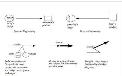
Figure 2.1: Reverse engineering derivatives (Nelson, 1996)
2.2.1 Reverse engineering
Reverse engineering in software engineering is the opposite of forward engineering, which is offered to indicate a traditional software development process (Nelson, 1996). The traditional software development often includes four phases: analysis, design, implementation, and testing. Through those phases, software is developed from the high level of abstraction (architecture) to the lowest level of abstraction (source code). Therefore, reverse engineering is the process which analyzes software system and then represents it at the higher levels of abstractions. The following definitions which is given by Chikofsky & Cross (1990) is widely used: "Reverse engineering is the process of analyzing a subject system to identify the system’s components and their interrelationships."
2.2.2 Restructuring
clear. This process only takes place in one abstraction level and its result is the representation of the system in another form depending on the purpose intended by the software engineers, but still at the same abstraction level, while reverse engineering deals with many abstraction levels and its result is the representation of the system at a higher level of abstraction. In addition, restructuring generates changes in the structure of the system, while reverse engineering only examines the structure of the system and does not make any changes in the system.
2.2.3 Reengineering
Reengineering is the examination, alteration, and modification of the system in order to regenerate a new system with new functions in another representation form (Chikofsky & Cross 1990). This term is wider than the reverse engineering term because it often includes both reverse engineering and forward engineering. The first phase in the reengineering process is using reverse engineering to understand the structure of the old system and represent it at a higher level of abstraction. At that time, some changes were generated at any level of abstraction. The second phase is developing the new system based on the new requirements or functions which have just been recently generated. This phase follows the steps in forward engineering. Hence, reengineering generates a new system with different features and functionalities from an old system, while reverse engineering does not make any changes in the features and functionalities of the system. Reverse engineering is a process of examination, not a process of replication.
2.3 Reverse engineering activities
According to Tilley (1998), the reverse engineering process includes three main activities: data gathering, knowledge management, and information exploration.
2.3.1 Data gathering
11
Therefore, data gathering is often the first step, where several types of data about the system are gathered such as the source code, comments in source code, documentation about the system, and experts’ comments. Three techniques of data gathering which are widely used are: system examination, document scanning, and experience capture (Tilley, 1998).
2.3.1.1 System examination
System examination is often classified into two constricting ways: static examination and dynamic examination. Static examination concentrates on analyzing the source code. A source code parser is often used to analyze the source code and then transfers it to abstract syntax trees (Bellay & Gall, 1998). In contrast, the dynamic examination focuses on the executing system. It is useful for understanding component-based systems in which the static examination cannot apply because components do not come with the source code. Analyzing systems when they are running helps us to have the knowledge about the interactions between components in the system, types of messages and protocols used, and the external recourses used by the system (Tilley, 1998).
2.3.1.2 Documents scanning
Document scanning is the process of gathering documents, another type of information about the system. For example, comments in the source code are useful sources for understanding the system. However, automatic analysis of the comments is more difficult as they may be isolated in the source code or they do not provide explicit information about the source code when they are not updated. Therefore, comments are often analyzed manually by the experts (Tilley, 1998).
2.3.1.3 Experience capturing
understanding the system. However, it is difficult to find out those that developed the system (Tilley, 1998).
2.3.2 Knowledge management
Knowledge management in reverse engineering is used to structure gathered data into a conceptual model of the application domain called a domain model. It includes three main steps namely knowledge organization, knowledge discovery, and knowledge evolution (Tilley, 1998).
2.3.3 Information exploration
According to Tilley (1998), the majority of program understanding takes place during information exploration, and it is arguably the most important of the three canonical reverse engineering activities. Data gathering is required to begin the reverse-engineering process. Knowledge management is needed to structure the data into a conceptual model of the application domain. But the key to increased comprehension is exploration because it facilitates the iterative refinement of the hypotheses. The process of information exploration includes three activities: navigation, analysis, and presentation (Tilley, 1998).
2.4 Unified Modelling Language (UML)
UML is defined by (OMG, 2008) as: "a graphical language for visualizing, specifying, constructing and documenting the artifacts of software systems". UML was originally derived from object modeling languages of three leading object-oriented methods: Booch, Object Modeling Technique (OMT), and Object-Oriented Software Engineering (OOSE). It is more compatible to be used to model object-oriented software systems.
13
2.4.1 UML model
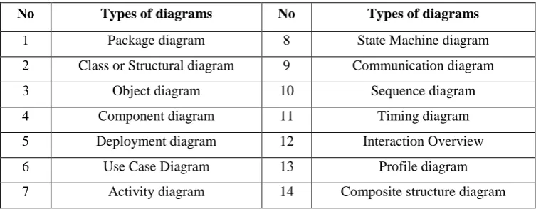
[image:23.595.113.490.609.756.2]The main purpose of UML is to provide a common vocabulary of object-oriented terms and diagramming techniques that enable developers to model any system. It is clear that UML has gained widespread acceptance as a notation for the analysis and design of software systems. According to Vidgen (2003), UML modeling helps in having a better understanding about a system. Currently, UML 2.4.1 specifies fourteen (14) UML diagrams (Ibrahim, N., 2013). They can be used to describe different views of a system. Structural view is specified by structure diagrams such as profile diagram, class diagram, composite structure diagram, component diagram, deployment diagram, object diagram, and package diagram, while the behavioral view is specified by behavior diagrams such as activity diagram, sequence diagram, communication diagram, interaction overview diagram, timing diagram, use case diagram, and state machine diagram (Ibrahim, N., 2013). Among the diagrams, UML class diagram, use case diagram, sequence diagram, and activity diagrams are the most frequently used diagrams by the UML practitioners (Dobing & Parsons, 2008, Grossman, et al., 2005). Each of the UML diagram is used to describe various aspects of a system. For example, use case diagram is used to highlight the main functions of a system and the roles that interact to it, while activity diagram is used to model the scenario of use cases in terms of dynamic aspect of a society of objects. On the other hand, sequence diagram is modeled to show the communication between objects in terms of sequence of messages, while the class diagram is to show the classes of the objects in term of their attributes, methods, and relationship with other classes. Table 2.1 presents the types of UML diagrams.
Table 2.1: UML 2.4.1 defines 14 diagrams (OMG, 2008)
No Types of diagrams No Types of diagrams
1 Package diagram 8 State Machine diagram
2 Class or Structural diagram 9 Communication diagram
3 Object diagram 10 Sequence diagram
4 Component diagram 11 Timing diagram
5 Deployment diagram 12 Interaction Overview
6 Use Case Diagram 13 Profile diagram
7 Activity diagram 14 Composite structure diagram
2.4.2 Overview of class diagram
[image:24.595.115.520.276.572.2]According to Matzko, et al. (2002), a class is represented as a box with three vertical sections. The top section shows the name of the class. The middle section displays the variables belonging to the class, with symbols representing the visibility (public, protected, or private) and properties (constant or static). The bottom section contains the member functions of the class. Each method has a name, signature, and properties. Relationship for each of the class will then be described by connection links (Miller, 2003). This description is illustrated in Figure 2.2.
Figure 2.2: Class Diagram of monitoring system of postgraduate student (Ibrahim & Tiu, 2008)
15
Relationship for each of the class will then be described by connection links (Miller, 2003). There are several relationships to be discussed which are association, multiplicity, generalization, dependency, realization, and aggregation. Each relationship is represented in the diagram by a different type of arrow. The following sections illustrate all types of relations with its visualization.
2.4.2.1 Association relationship
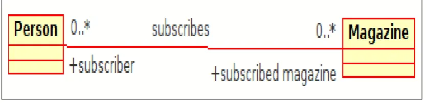
[image:25.595.113.531.385.486.2]According to Matzko, et al. (2002), an association is a structural relationship that describes a set of links, where a link is a connection among objects. Class A has an association with class B if class A has a data member of type B. Associations are often adorned with numbers or symbols representing the multiplicity of the relationship, or how many objects of one class from the other is used. Figure 2.3 shows an example of association relationship.
Figure 2.3: Class diagram example of association between two classes (Wiki, 2014) The association relationship is used as a measure of closeness among the system files. Also, it can be used for finding data sharing. So, it is very important to include reverse engineering of association (Vinita, et al., 2008).
2.4.2.2 Aggregation relationship
association. Aggregation can occur when a class is a collection or container of other classes, but the contained classes do not have a strong lifecycle dependency on the container. In UML, it is graphically represented as a hollow diamond shape in the containing class with a single line that connects it to the contained class. The aggregate is semantically an extended object that is treated as a unit in many operations, although physically it is made of several lesser objects. Figure 2.4 shows an example of aggregation relationship.
Figure 2.4: Class diagram showing Aggregation between two classes (Wiki, 2014)
2.4.2.3 Composition relationship
17
Figure 2.5: Class diagram showing Composition between two classes at the top and Aggregation between two classes at bottom (Wiki, 2014)
2.4.2.4 Multiplicity relationship
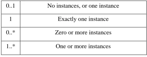
This association relationship indicates that (at least) one of the two related classes make reference to the other. This relationship is usually described as "A has a B" (a mother cat has kittens, kittens have a mother cat) (Scott, 2009). The UML representation of an association is a line with an optional arrowhead indicating the role of the object(s) in the relationship, and an optional notation at each end indicating the multiplicity of instances of that entity (the number of objects that participate in the association). Table 2.2 shows the multiplicity indicators.
Table 2.2: Multiplicity Indicators (Agile, 2014)
0..1 No instances, or one instance
1 Exactly one instance
0..* Zero or more instances
1..* One or more instances
2.4.2.5 Generalization relationship
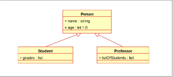
[image:27.595.199.438.528.622.2]of the superclass. The UML graphical representation of a Generalization is a hollow triangle shape on the superclass end of the line (or tree of lines) that connects it to one or more subtypes. The generalization relationship is also known as the inheritance or "is a" relationship. The superclass (base class) in the generalization relationship is also known as the "parent", superclass, base class, or base type. The subtype in the specialization relationship is also known as the "child", subclass, derived class, derived type, inheriting class, or inheriting type. Figure 2.6 shows an example of generalization relationship.
[image:28.595.148.515.257.421.2]
Figure 2.6: Class diagram showing generalization between one superclass and two subclasses (Wiki, 2014)
One of the major activities in software development is the process of generalizing components. We like generalized (inherited) code because it can be reused in various applications. When it has been thoroughly tested and its use properly documented, generalized code saves the user of that code considerable time and effort (Vinita, et al., 2008).
2.4.2.6 Realization relationship
19
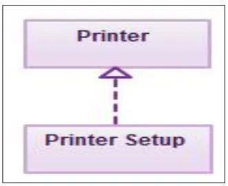
[image:29.595.236.402.225.360.2]connects it to its users. Realizations can only be shown in class or component diagrams. A realization is a relationship between classes, interfaces, components, and packages that connects a client element with a supplier element. A realization relationship between classes and interfaces and between components and interfaces shows that the class realizes the operations offered by the interface. In the example below, the printing preferences that are set using the printer setup interface are being implemented by the printer. Figure 2.7 shows an example of realization relationship.
Figure 2.7: Class diagram showing realization relationship (Nishadha, 2012) The main use of realization or interface is reusability. It allows us to reuse a lot of code and make things simpler at the same time. Interfaces promote abstraction. In case if we want to use some class for its functions only, we have to define the interface in which we just use the implementation part only. So, realization rule specifies the corresponding alternate UML class diagram representations (Vinita, et al., 2008).
2.4.2.6 Dependency relationship
be "Car depends on Wheel", because Car already aggregates (and not just uses) Wheel).
Figure 2.8: Dependency relationship example (Wiki, 2014)
Dependency plays an important role in the understanding of code as the relationship correctly depicts how the effects of a change in one class are being propagated into another class. During the process of reverse engineering it is necessary to incorporate dependency not to lose any important information regarding lower level abstraction and/or any other functional or structural representation (Vinita, et al., 2008).
2.5 C# programming language
C# (pronounced C sharp) is a programming language designed for building a wide range of enterprise applications which runs on the .NET Framework. It evolved from Microsoft C and Microsoft C++ and is a simple, modern, type safe, and object oriented programming language. C# code is compiled as managed code, which means that it benefits from of the services of the common language runtime. These services include language interoperability, garbage collection, enhanced security, and improved versioning support (MSDN, 2014).
21
type is derived from the type object (MSDN, 2014). Types in C# are divided in two groups: Value Types - all primitive types (int, float, string,...). {Reference Types - classes, delegates, interfaces}.
Value types differ from reference types, and this is because value types directly contain their data, whereas variables of the reference types store references to the object. With reference types, it is possible for two variables to reference to the same object, and it is possible for operations of one variable to act as the object referenced by the other variable. With value types, each variable has its own copy of the data, and it is not possible for operations of one variable to act as the operation of the other (MSDN, 2014).
2.6 Sequential and Parallel approaches
Figure 2.9: standard steps of Parallel approach (Mivule, 2011)
Figure 2.10: standard steps of Sequential approach (Mivule, 2011)
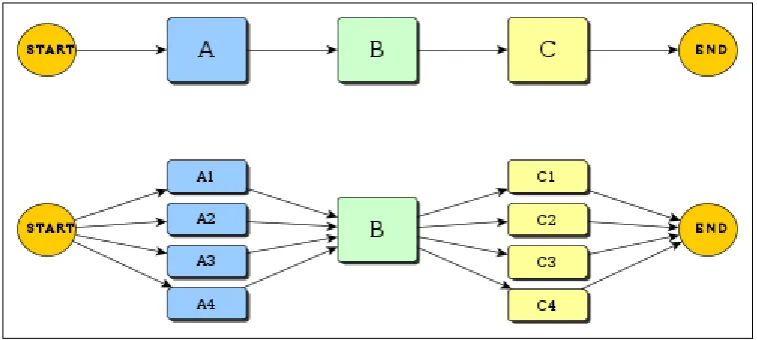
Xmipp (2010), mentioned that a program that perform tasks A, B, and C sequentially, and tasks A and C task can be threaded. So, task A can be split in several concurrent tasks and implemented in parallel as A1, A2, A3... An, and the same for C. Figure 2.11 shows the sequential and parallel version of the program execution.
[image:32.595.130.509.524.694.2]23
2.7 Multi-Threading technique
According to Butenhof (1997), a thread of execution is the smallest sequence of programmed instructions that can be managed independently by an operating system scheduler. The implementation of threads and processes differ from one operating system to another, but in most cases, a thread is contained inside a process. Multiple threads can exist within the same process and share resources such as memory, while different processes do not share these resources. In particular, the threads of a process shares the latter's instructions (its code) and its context (the values that its variable reference at any given moment) (Butenhof, 1997).
2.7.1 Multi-Threading description
According to Justia (2013), multi-threading paradigm has become more popular as efforts to further exploit instruction level parallelism have stalled since the late 1990s. This allowed the concept of throughput computing to re-emerge to prominence from the more specialized field of transaction processing:
Even though it is very difficult to further speed up a single thread or single program, most computer systems are actually multi-tasking among multiple threads or programs. Techniques that would allow speedup of the overall system throughput of all tasks would be a meaningful performance gain (Justia 2013).
Justia (2013) highlighted two major techniques for throughput computing as being: multiprocessing and multi-threading. These two techniques are explained in the following paragraphs:
Multiprocessing systems include multiple complete processing units, while multi-threading aims to increase the utilization of a single core by using thread-level as well as instruction-level parallelism. As the two techniques are complementary, they are sometimes combined in systems with multiple multi-threading CPUs and in CPUs with multiple multi-threading cores (Justia, 2013).
According to Barnes, et al., (2012) the advantage of a multithreaded program allows it to operate faster on computer systems that have multiple CPUs, CPUs with multiple cores, or across a cluster of machines, because the threads of the program naturally lend themselves to truly concurrent execution.
2.7.2 Thread code implementation
The term thread code refers to a compiler implementation technique where the generated code has a form that essentially consists entirely of calls to subroutines (Ertl, 2003). The code may be processed by an interpreter, or may simply be a sequence of machine code call instructions. However, a program small enough to fit fully in a computer processor's cache may run faster than a larger program that suffers many caches misses (Bell & James, 2003). Threaded code is best known as the implementation technique commonly used by programming languages.
2.7.3 Thread pool concept
69
REFERENCES
Agile. (2014). UML 2 Class Diagrams: An Agile Introduction. Retrieved on 07/03/2014,from: http://www.agilemodeling.com/artifacts/classDiagram.htm. Aziz, N., Karla Morris and Salvatore Filippone (2013). Extracting UML class
diagrams from object-oriented Fortran: ForUML. Proceedings of the 1st International Workshop on Software Engineering for High Performance Computing in Computational Science and Engineering (SE-HPCCSE '13). New York: ACM, pp 9-16.
Barnes, A., Ryan Fernando, Kasuni Mettananda and Roshan Ragel (2012). Improving the Throughput of the AES Algorithm with Multi core Processors. Proceeding of the 7th International Conference on Industrial and Information Systems (ICIIS). Chennai: IEEE.pp.1-6.
Bell, and James R. (2003). Threaded code. Communications of the ACM, ACM, 16 (6), pp. 370–372.
Bellay, B. and Gall, H.(1998). An evolution of reverse engineering tool capabilities. Journal of Software Maintenance: Research and practice, 10(5), pp. 305-33. Britannica (2010). Sequence Programming Britannica Online Encyclopedia.
Retrieved on 13/05/2014 from:
http://www.britannica.com/EBchecked/topic/1086517/sequence.
Boehm, B.W.(1991). Software Engineering Economics. 1st edition.USA: Prentice Hall.
Butenhof, D.R. (1997). Programming with POSIX Threads. 1st edition. Boston, USA: Addison-Wesley.
Canfora, G. and Penta, M. (2007). New Frontiers of Reverse Engineering. Future of Software Engineering (FOSE '07). Minneapolis: IEEE. pp. 326-341.
Chikofsky, E. and Cross, J. I. (1990). Reverse engineering and design recovery: A taxonomy. IEEE Software, 7(1), pp. 13-17.
Dennis, A., Wixom, B.H. and Roth, R.M. (2006). Systems Analysis and Design. 3rd edition. Hoboken: John Wiley & Sons, Inc.
Dobing, B. and Parsons, J. (2006). How UML is used. Communications of the ACM - Two decades of the language-action perspective, ACM, 49(5).pp. 109-114. Ertl, A. what is threaded code. Retrieved on 11/03/2014 from:
http://www.complang.tuwien.ac.at/forth/threaded-code.html#what
Fjeldstad, R.K., and Hamlen W.T. (2001). Application Program Maintenance Study: Report to Our Respondents. Tutorial on Software Maintenance. IEEE Computer Society Press.pp. 13 – 30.
Goetz, B. (2002). Java theory and practice: Thread pools and work queues. IBM
DeveloperWorks. Retrieved on 12/03/2014 from:
http://www.ibm.com/developerworks/java/library/j-jtp0730/index.html. Grossman, M., Aronson, J. E. and McCarthy, R. V. (2005). Does UML make the
grade? Insights from the software development community. Information and Software Technology, 47(6), pp. 383-397.
Harvey, B.,Wright, M. (1999). Simply scheme: introducing computer science. 2nd edition. California: MIT Press.
Ibrahim, N.(2013). An Enhanced UML Consisteccy Cecker Using Logical Approach. Universiti Tun Hussein Onn Malaysia: Ph.D. Dissertation.
Ibrahim, R. & Yong, T.K. (2008). ReSeT: Reverse Engineering System Requirements Tool. World Academy of Science, 14(4), pp.238-241.
Jain, A., Sooner, S, and Holkar, A. (2010). Reverse engineering: Extracting information from C++ code. Proceedings of the 2nd International Conference on Software Technology and Engineering (ICSTE). San Juan: IEEE. pp. 154 -158 .
Justia (2011). Obfuscated hardware multi-threading. Retrieved on 31/03/2014, from http://patents.justia.com/patent/8621186.
Justia. (2013). Multi-threading Computers. Retrieved on 11/03/2014 from: http://patents.justia.com/patent/20140047219.
Keschenau, M. (2006). Reverse Engineering of UML Specifications from Java Programs. Proceedings of the 19th companion annual conference on Object-oriented programming systems (OOPSLA '04).New York:ACM,pp 326-327.
71
mobile and embedded applications (CRPIT'02). Australia: ACM, 10(4), pp.13-21.
Mazhou.(2010). What are actually synchronous/asynchronous operations (C# 5.0 Series). Retrieved on 05/07/2014, from
http://www.codeproject.com/Articles/127660/What-are-actually-synchronous asynchronous-operati.
Mivule, K. (2011). Difference between Sequential and Parallel Programming. Retrieved on 12/05/2014 from:
https://mivuletech.wordpress.com/2011/01/12/difference-between-sequential-and-parallel-programming/.
Miller, R. (2003). Practical UML : A Hands-on Introduction for developer. Retrieved on 05/03/2014, from http://dn.codegear.com/article/31863.
MSDN. (2014). Microsoft Corporation. Retrieved on 08/03/2014, from: http://msdn.microsoft.com/en-us/default.aspx.
Nagappan, S.D. (2008). A reverse engineering uml modeling tool. University of Malaya: Master’s Dissertation.
Nelson, M.L. (1996). A survey of reverse engineering and program comprehension, A Survey of Reverse Engineering and Program Comprehension. Computing Research Repository - CORR.pp.1- 8.
Nishadha. (2012). Class Diagram Relationships in UML with Examples. Retrieved on 08/03/2014, from:http://generately.com/blog/diagrams/class-diagram-relationships/.
OMG (2008). Unified Modeling Language UML, http://www.omg.org/-spec/UML/, 2008. OMG Formally Released Versions of UML and ISO Released Versions of UML. p. 20,40, 116.Pages 212-229.
Ramasubbu, S. (2001). Reverse Software Engineering Large Object Oriented Software Systems using the UML Notation. Virginia Polytechnic Institute and State University: Master’s Dissertation.
Rohitha. (2011). Understanding UML Class Diagram Relationships. Retrieved on 07/03/2014, from: http://generately.com/blog/diagrams/understanding-the-relationships-between-classes/.
Rugaber,S. (1992). Program Comprehension for Reverse Engineering. Workshop on AI and Automated Program Understanding.
http://www.agilemodeling.com/artifacts/classDiagram.htm
Sparks, G. (2001). Database Modelling in UML. Retrieved on 06/03/2014, from http://www.methodsandtools.com/archive/archive.php?id=9.
Sutton, A. and Maletic, J.I. (2007). Recovering UML class models from C++: A detailed explanation. Information and Software Technology. 49(3), pp 212-229.
Thaara, S. (2002). Thread Pool Pattern. Retrieved on 12/03/2014 from: http://www.scribd.com/doc/240669342/Thread-Pool-Pattern.
Tilly, S.T.(1998). A reverse engineering environment framework. Technical report CMU/SEI, Hanscom: Software Engineering Institute.
Tonella, P. (2005). Reverse Engineering of Object Oriented Code. Proceeding of the. 27th International Conference on Software Engineering ICSE 2005.IEEE .pp.724- 725.
Tonella, P., and Potrich, A. (2001). Reverse engineering of the UML class diagram from C++ code in presence of weakly typed containers. Proceeding of International Conference on Software Maintenance. Florence: IEEE.pp. 376 – 385.
Tokhi, Mohammad, A. H. and Mohammad, H. S. (2003). Parallel computing for real-time signal processing and control, Advanced textbooks in control and signal processing.43(11),pp 1545-1568.
Vidgen, R. (2003). Requirements analysis and UML use cases and class diagrams. Computing & Control Engineering Journal.14(2).pp.12 - 17.
Vinita; Amita Jain and Devendra K. Tayal. (2008). On reverse engineering an object-oriented code into UML class diagrams incorporating extensible mechanisms. ACM SIGSOFT Software Engineering Notes. 33(5), pp.1-9.
Wiki. (2007). Thread pool. Retrieved on 12/03/2014 from: http://en.wikipedia.org/w/index.php?title=File:Thread_pool.svg.
Wiki. (2014). Class diagram relationships examples. Retrieved on 06/03/2014, from: http://en.wikipedia.org/wiki/Class_diagram