Journal of Chemical and Pharmaceutical Research, 2014, 6(5):1135-1141
Research Article
CODEN(USA) : JCPRC5
ISSN : 0975-7384
Study on influence factor of braking torque in liquid-cooled eddy
current retarder with a structure of two salient poles
Zhang Long Xi, Li De Sheng and Yin Wang Lei
College of Mechanical Engineering and Applied Electronic Technology, Beijing University of Technology,
Beijing, China
_____________________________________________________________________________________________
ABSTRACT
To systematic study the factors which influence the braking torque in liquid-cooled eddy current retarder with a structure of two salient poles, we analyze the related theory of electromagnetics and the formulas for the braking torque of eddy current retarder (ECR) were deduced on the basis of the working principle of liquid-cooled ECR with a structure of two salient poles. And the braking system model was built, the electrical conductivity and magnetic permeability of materials, the excitation current and the rotor speed on retarder braking torque have been studied by JMAG software. The theoretical and finite element analysis was verified and the general regularity of the influence factors of braking torque in liquid-cooled ECR was obtained through the prototype test.
Key words: a structure of two salient poles, eddy current retarder (ECR), liquid-cooled, braking torque,
electromagnetic
_____________________________________________________________________________________________
INTRODUCTION
With the rapid development of the automotive technology, more and more automotive capabilities have been required, such as the power performance, safety, riding comfort and environmental protection. The vehicle retarder is a novel energy-saving, environmental friendly auxiliary device developed in recent years and it is a major part of the vehicle braking system [1]. The liquid-cooled eddy current retarder (ECR) with a structure of two salient poles is a kind of vehicle retarder, which has been gained wide attention. The working principle, structure and electromagnetic field of the ECR have been studied in this literature [2-3] which provides a theoretical basis for the further research on retarder. When the retarder works, the stator generates eddy current which has skin effect, and it has a great negative effect on the braking effect of the rotor. The selection of the appropriate stator material properties can reduce this impact [4-5].The literature [6-8] also mentioned that if the inner surface of the rotor or stator is plated by a plating layer of high conductivity copper block or embed a copper billet can effectively improve the performance of the retarder. Thus, the material properties of the stator and the rotor have a great influence on the braking performance. In addition, according to the law of Faraday's electromagnetic induction, the excitation current and speed are the main factors affecting the braking torque.
ELECTROMAGNETIC THEORY ANALYSIS
______________________________________________________________________________
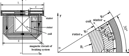
Fig. 1: Analysis model of ECRFig.2: Analysis model of the FEM
A BRAKE POWER AND BRAKE TORQUE OF ECR
When the rotational speed of the rotor is low, dynamic magnetic induction intensity and static magnetic induction intensity are approximately equal. So the dynamic magnetic problem can be transformed to static magnetic problem to be solved. The static magnetic induction intensity is given by the following formula:
B = ≈ / (1)
Whereµ0 is the permeability of air, = 4 × 10 #H/m, $is the relative permeability of stator,%&is the sectional area of stator, L is the axial length of rotor, δ is the air-gap length.
The current density under the magnetic pole is given by'(= )* +, the braking power generated by eddy current in unit volume of stator isρ'(,then the braking power of stator is given by
P = ∯ /'(01 (2)
Whereρ = 1 )⁄ , ρ is resistivity, V is the distribution of the eddy current volume.
Combined the ECR which is shown in Fig.2 and the circumferential velocity of the rotor saliencyυ = 4567, the formula is given by
P =8#9 / : ;< 67 (3)
Where67is the rotor angular velocity,67= 2 > 60⁄ ;I is exciting current intensity.
The braking torque generated by one magnetic pole is given by
M =<AB=
8#9C D ED F : ;
< 67=8#9C D ED F :
G7;
H8 I (4)
Where Np is magnetic poles logarithmic, Np=12; n is rotational speed.
Some factors are not considered in actual working process of the ECR in formula (4), such as the magnetic flux leakage, magnetic saturation and temperature effect of the material. But it can be solved by modifying the coefficient C [9], the actual effect on the rotor braking torque is
JK= LJ = L
8#9C D ED F : G7;
H8 I (5)
Where (5) is the braking torque generated by one magnetic pole, ignoring the interaction between magnetic poles, thus the total braking torque of the ECR is given by
J = 2MAJK= L
8#9C D ED F : G7;
From the formula (6) we can see that the braking torque of the ECR is not only related to the size parameters of the rotor, but also related to the electrical conductivity and permeability of stator. Excitation winding turns and the intensity of electric current and rotor speed are also the main factors influencing the braking torque.
FINITE ELEMENT ANALYSIS
Since the liquid-cooled ECR with a structure of two salient poles has a symmetrical structure, and a rotation period, in order to facilitate the analysis and calculation, effectively save computational resources and shorten the time of calculation, a 1/24 model of the ECR was built. Fig.2 shows the analysis model of the FEM. The stator and rotor material is steel 10, the excitation coil is copper, Tab.1 shows the main geometrical parameters of the analyzed model.
In the process of analyzing of the braking torque for the ECR, the following assumptions were made: 1) Ignoring the curvature and density of the displacement current; 2) Neglecting the hysteresis loss and stray loss.
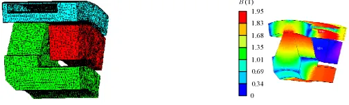
In this paper, we used JSOL JMAG software which developed in Japan to analyze electromagnetic module. The software is used in various electrical and magnetic fields to accurately analyze the electromagnetic devices. We also use JMAG-Designer software model of the electromagnetic field to analyze ECR. After setting materials and boundary conditions, meshing (Fig.3), solving option, conducting finite element solver and post-processing and parameter extraction step, then we can get the post-treatment retarder dimensional static magnetic field vector distribution (Fig.4).
Table1 parameters of the ECR
Parameters Values Parameters Values
φ/° 30 R1/mm 113
R2/mm 153 R3/mm 242
H/mm 71 g/mm 1
A/mm 21 R4/mm 243
θ/° 16 R5/mm 272.5
In order to systematically research the influence factors of baking performance, the relationship between the stator and rotor material electrical conductivity, permeability, the excitation current and the rotor rotational speed and braking torque were studied by numerical simulation parameter.
[image:3.595.181.433.450.526.2]
Fig. 3: Model of the ECR and mesh Fig.4: Magnetic field distribution of the ECR
A ELECTRICAL CONDUCTIVITY IMPACT ON BRAKING TORQUE
Since the retarder is a kind of auxiliary braking device, which converts the kinetic energy of the automobile into heat energy, the long working of the retarder made the stator temperature rise sharply, the maximum temperature is up to
600℃. It may result the stator’s conductivity decrease, formula (7) is a resistor temperature relationship.
R = 4 1 + P Q − Q (7)
Where R is resistance when the temperature is T, R0 is resistance when the temperature is T0, α is temperature coefficient of resistance.
Fromρ = 1 )⁄ , refer to the formula (7), we can obtain the relationship between stator conductivity and temperature
σ = ) 1 + P Q − Q⁄ (8)
Where ) is the conductivity of the material at the time ofQ.
______________________________________________________________________________
we can get the curve when speed n = 1000r/min, the excitation current of 30A conductivity changes braking torque
relationship with the stator shown in Fig.6. From the Fig.6, when the conductivity is less than 5×10⁶(S•m-1),the
braking torque is a substantially linear relationship, when the conductivity is greater than 5×10⁶(S•m-1), since the set of vortex skin effect, the skin depth ΔWbecomes smaller, so that the growth rate of the braking torque decreases and gradually saturated. Conductivity continues to increase, but the braking torque decreases. However, the rotor material conductivity has a little effect on retarder braking torque. For an individual, the conductivity mainly influenced by the temperature rise in the working process, if not using the method of water-cooled cooling, it’s very easy to cause stator conductivity decreases, which is the main reason causing the thermal recession of eddy current retarder.
1000 1200 1400 1600 1800 2000 2200 2400
0 2 4 6 8 10
[image:4.595.125.256.201.278.2] [image:4.595.394.478.219.278.2] [image:4.595.137.249.472.548.2]rotor stator
Fig. 5: Conductivity-temperature curve Fig.6: Braking torque-conductivity curve
B PERMEABILITY IMPACT ON BRAKING TORQUE
By Curie-Weiss law, the relative permeability in high temperature can be given as follows:
$= 1 + L/ Q − QX (9)
Where C is Curie constant,QXis Curie temperature.
Magnetic induction B=µH,µ=µ0µr.Therefore, under the certain magnetic field intensity H, B value depends on the material permeability µ. Choosing a material with high µ value can reduce the strength of the external magnetic field current, thereby reducing the volume of the excitation device. From literature [10], we can conclude that using the same material and the different heat treatment, its µ values are difference, the B-H curve of the material also makes the corresponding change. Fig.7 shows the B-H curves of Steel 10 in different heat treatments.
0 0.4 0.8 1.2 1.6 2
0 4000 8000 12000 16000
1000 1200 1400 1600 1800 2000 2200 2400
0 100 200 300
stator rotor
Fig. 7: B-H curve of Steel 10in different heat treatment Fig.8: Braking torque- Relative permeability curve
As can be seen from Fig.8, the impact of the stator magnetic permeability on the braking torque is not obvious than the electrical conductivity. And the conductivity constant, magnetic permeability is increased, the braking torque is reduced. Within a certain range, the braking torque is linear rapidly changing along with the rotor magnetic permeability; magnetic permeability increasing, the braking torque changes tend to be gentle, illustrating the magnetic circuit has been saturation.
C EXCITATION CURRENT IMPACT ON BRAKING TORQUE
[image:4.595.387.465.493.554.2]200 400 600 800 1000 1200 1400 1600 1800 2000
0 5 10 15 20 25 30 35 40 45 exciting current I(A)
b ra k in g t o rq u e T (N m ) 0.5 0.7 0.9 1.1 1.3 1.5 1.7 1.9 2.1 a ir g a p f lu x d e n si ty B a v (T ) braking torque
average air gap flux density
0 300 600 900 1200 1500 1800 2100 2400
0 50010001500200025003000
rotational speed v(rpm )
b ra k in g t o rq u e T (N m ) 1.3 1.4 1.5 1.6 1.7 1.8 1.9 2 2.1 10Abraking torque 40Abraking torque
[image:5.595.358.505.74.180.2] [image:5.595.99.247.79.182.2]10Aaverage air gap flux density 40Aaverage air gap flux density
Fig. 9: Braking torque and Flux density at various current Fig.10: Braking torque and Flux densityat various speeds
D ROTATIONAL SPEED IMPACT ON BRAKING TORQUE
Through the analysis above, when the excitation current increased from 10A to 40A, its saturation degree increases, but the braking torque increases slowly. By parametric numerical simulation calculations, investigating how the rotational speeds impact on the braking torque of ECR in the two conditions of the excitation current both 10A and 40A, and drawing the curve of the braking torque and the average air gap flux density at various rotational speeds. The braking torque and air gap flux density curves in Fig.10 shows the value of the excitation current for 10A or 40A. When the rotational speed was low(less than 500rpm), the two kinds of braking torque and average air gap flux density are very close to. However, because of the existence of eddy current, anti-MMFs are developed with the rotation rate of the rotor, so that the average air gap flux density is decreased. With the rotational speed increasing, the eddy current density would increase, thus its anti-MMFs also increased. Meanwhile, the difference of the two kinds of braking torque and average air gap flux density are increasing. It shows that the eddy current anti-MMFs can weaken different saturation degree of air gap flux density with different degree.
EXPERIMENT
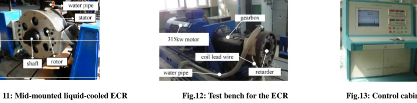
In order to verify the correctness of the theory and simulation analysis, a prototype of the mid-mounted liquid-cooled ECR with a structure of two salient poles (Fig.11) was developed based on the previous analysis. In order to test the ECR performance, the test system was built and the braking torque characteristics were measured using the test bench which was shown in Fig.12.The flow rate of the liquid was about 3L/s.
The test-bed was made of a 315kW, dc-motor, a gearbox, and a speed regulating device. A torque indicator was installed on the output shaft of the dc-motor. The gearbox was connected the dc-motor. The ECR was connected by a transmission shaft to the gearbox. The water temperature of the pipe outlet was measured by a sensor. Test data were collected by a computer-centralized control system which was installed in the control cabinet (Fig.13). The excitation current was supplied by the battery through the control system.
[image:5.595.100.516.501.604.2]
Fig. 11: Mid-mounted liquid-cooled ECR Fig.12: Test bench for the ECR Fig.13: Control cabinet
A REGULATING CHARACTERISTIC
______________________________________________________________________________
0 400 800 1200 1600 2000
0 5 10 15 20 25 30 35 40 45
calculation measurement
200 400 600 800 1000 1200 1400 1600 1800
0 200 400 600 800 1000 1200 1400 1600
calculation measurement
Fig. 14: Regulation characteristic curve Fig.15: Speed characteristic curve
B SPEED CHARACTERISTIC
The speed characteristic of the retarder means the braking torque with the variation of the rotational speeds when the retarder under a certain value of excitation current. Fig.15 shows the comparison curve of the braking torque at various speeds by both measurements and calculations when the value of excitation current for 40A. Obviously, the change trend of speed characteristic curve of the simulation was consistent with the experimental results, which further verified the correctness of the theoretical analysis. The experimental values was slightly lower than the simulation results, the reason is the simplified model of the liquid-cooled ECR with a structure of two salient poles without considered the magnetic flux leakage. But in reality, there were the existence of magnetic flux leakage in the retarder. In addition, in the process of the machining and assembly of the retarder prototype, the structure parameters of the rotor salient poles and the additional air gap size were difficult to guarantee completely consistent with the design values.
CONCLUSION
In this paper, formulas for the braking power and the braking torque of the ECR were deduced on the basis of introducing the working principle of liquid-cooled ECR with a structure of two salient poles. The main factors affecting the performance of the retarder were analyzed and calculated by using three-dimensional finite element methods. Finally, through testing a prototype of the mid-mounted liquid-cooled ECR with a structure of two salient poles, we verified the correctness of the theoretical analysis and simulation analysis. Besides, the test results demonstrated that the liquid-cooled approach could effectively overcome the serious problem of braking torque heat recession when the traditional ECR continuous working.
Further study should consider the demagnetization effect and magnetic saturation and so on to get more accurate and suitable calculation formula for the whole braking process of the braking torque, optimize the design of the product.
Acknowledgments
The authors thank Du Xiao and Wang Cong for help in the braking torque and thermal filed analysis. This work is supported by the National Natural Science Foundation of China under Project 51277005.
REFERENCES
[1]HE Ren. Automobile Auxiliary Brake. 1st Edition, Chemical Industry Press, Beijing,2005: 116-128.
[2]LI Desheng, DU Xiao, YE Lezhi. Salient construct liquid-cooled eddy current retarder[P]. ZL201210061975.6.
2012-07-25.
[3]JIAO Bingfeng. Multi-field coupled analysis and optimization of the Electromagnetic Liquid-cooled Retarder [D]. Beijing University of Technology, 2013.
[4]BIGEON J, SABONNADIERE J, COULOMB J. Academic J.IEEE Transactions on Magnetics,1983, 19(6) :
2632-2634.
[5]WOUTERSE J H.Academic J.ProcInst Elect Eng, 1991, 138(4) : 153-168.
[6]YAO Yeongder,CHIOU Gwoji,HUANG Der-ray.Academic J. IEEE Transactions on Magnetics,1995,31(3) :
1881-1884.
[7]KUWAHARA Tohru.Composite magnet of electromagnet and permanent magnet,and eddy current retarder: US,
6756870B2[P].2004--06--29[2009--10--10].
[8]LI Zheng sheng.Eddy-current wheel end retarder featuring modified rotor skin effect: US,20040262105A1[P].
[9]LAI Sanxia, LI Gangyan, HILLION Thomas etc. Academic J. Auto Mobile Science & Technology,
2006,5(9):27-29.