International Journal of Emerging Technology and Advanced Engineering
Website: www.ijetae.com (ISSN 2250-2459, ISO 9001:2008 Certified Journal, Volume 2, Issue 12, December 2012)
275
Friction Stir Welding – Process and its Variables: A Review
Mandeep Singh Sidhu
1, Sukhpal Singh Chatha
2
Department of Mechanical Engineering, Yadavindra College of Engineering, Punjabi University Campus, Talwandi Sabo, Bathinda, Punjab-151302, India.
Abstract— Friction Stir Welding (FSW) was invented by
Wayne Thomas at TWI (The Welding Institute), and the first patent applications were filed in the UK in December 1991. Initially, the process was regarded as a “laboratory” curiosity, but it soon became clear that FSW offers numerous benefits in the fabrication of aluminium products. Friction Stir Welding (FSW) has become a major joining process in the aerospace, railway and ship building industries especially in the fabrication of aluminium alloys. The process uses a spinning non-consumable tool to generate frictional heat in the work piece. Worldwide, there are now over 135 licensees of FSW and new techniques and applications are being developed daily. This paper looks at the review, on friction stir welding process, various welding variables like tool rotation, transverse speed, tool tilt, plunge depth and tool design, for the welding of aluminium alloys or various dissimilar alloys. Applications, future aspects and several key problems are also described.
Keywords— Keyword Friction Stir Welding, tool rotation and transverse speed, tool tilt and plunge depth tool design
I. INTRODUCTION
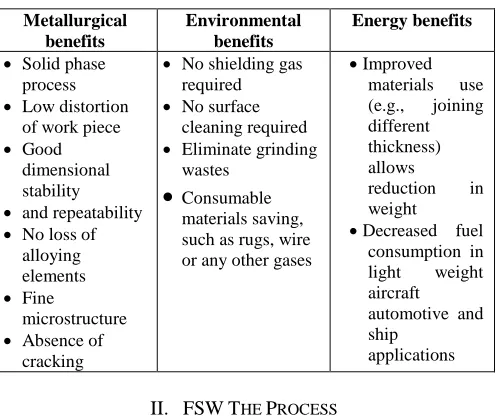
[image:1.612.322.571.229.439.2] [image:1.612.324.571.231.437.2]This document is template. Friction stir welding (FSW) is an innovative welding process commonly known as a solid state welding process. This opens up whole new areas in welding technology. It is particularly appropriate for the welding of high strength alloys which are extensively used in the aircraft industry. Mechanical fastening has long been favored to join aerospace structures because high strength aluminum alloys are difficult to join by conventional fusion welding techniques (Pouget G. et al., 2007). Its main characteristic is to join material without reaching the fusion temperature. It enables to weld almost all types of aluminium alloys, even the one classified as non-weldable by fusion welding due to hot cracking and poor solidification microstructure in the fusion zone (Zimmer Sandra et al., 2009). FSW is considered to be the most significant development in metal joining in a decade and is a ‗‗green‘‘ technology due to its energy efficiency, environment friendliness, and versatility. The key benefits of FSW are summarized in Table 1(Mishra R.S. et al., 2005).
Table 1
Key benefits of FSW are summarized below.
Metallurgical benefits
Environmental benefits
Energy benefits
Solid phase process Low distortion
of work piece Good
dimensional stability and repeatability No loss of
alloying elements Fine
microstructure Absence of
cracking
No shielding gas required No surface
cleaning required Eliminate grinding
wastes
Consumable
materials saving, such as rugs, wire or any other gases
Improved materials use (e.g., joining different thickness) allows
reduction in weight Decreased fuel
consumption in light weight aircraft automotive and ship
applications
II. FSWTHE PROCESS
The working principle of Friction Stir Welding process is shown in Fig. 1. A welding tool comprised of a shank, shoulder, and pin is fixed in a milling machine chuck and is rotated about its longitudinal axis. The work piece, with square mating edges, is fixed to a rigid backing plate, and a clamp or anvil prevents the work piece from spreading or lifting during welding. The half-plate where the direction of rotation is the same as that of welding is called the advancing side, with the other side designated as being the retreating side (Nandan R. et al., 2008). The rotating welding tool is slowly plunged into the work piece until the shoulder of the welding tool forcibly contacts the upper surface of the material.
International Journal of Emerging Technology and Advanced Engineering
Website: www.ijetae.com (ISSN 2250-2459, ISO 9001:2008 Certified Journal, Volume 2, Issue 12, December 2012)
276
Fig.1 The principle of Friction Stir Welding (Eur. Ing. Wayne Thomas).
III. WELDING VARIABLES
FSW involves complex material movement and plastic deformation. Welding parameters, Tool geometry and joint design exert significant effect on the material flow pattern and temperature distribution, thereby influencing the micro structural evolution of material (Mishra R.S. et al., 2005). Therefore, welding speed, the tool rotational speed, the tilt angle of the tool, tool material and the tool design are the main independent variables that are used to control the FSW process.
The main process parameters and there effects in friction stir welding are given below Table 2 (FSW-Technical-Handbook).
Table2
Main process parameters in friction stir welding.
Parameter Effects
Rotation speed Frictional heat, ―stirring‖, oxide layer breaking and mixing of material. Tilting angle The appearance of the weld, thinning. Welding speed Appearance, heat control.
Down force Frictional heat, maintaining contact conditions.
A. Tool rotation and Transverse speed
For FSW, two parameters are very important: tool rotation rate (v, rpm) in clockwise or counter clockwise direction and tool traverse speed (n, mm/min) along the line of joint. The motion of the tool generates frictional heat within the work pieces, extruding the softened plasticized material around it and forging the same in place so as to form a solid-state seamless joint (Xunhong Wang et al., 2006).
As the tool (rotates and) moves along the butting surfaces, heat is being generated at the shoulder/work-piece and, to a lesser extent, at the pin/work-piece contact surfaces, as a result of the frictional-energy dissipation (Grujicic M. et al., 2010).
The welding speed depends on several factors, such as alloy type, rotational speed, penetration depth, and joint type (Sakthivel T. et al., 2009). Higher tool rotation rates generate higher temperature because of higher friction heating and result in more intense stirring and mixing of material. During traversing, softened material from the leading edge moves to the trailing edge due to the tool rotation and the traverse movement of the tool, and this transferred material, are consolidated in the trailing edge of the tool by the application of an axial force (Kumar K., et al., 2008).
B. Tool tilt and Plunge depth
In addition to the tool rotation rate and traverse speed, another important process parameters are tool tilt with respect to the work piece surface and plunge depth. A suitable tilt of the spindle towards trailing direction ensures that the shoulder of the tool holds the stirred material by threaded pin and move material efficiently from the front to the back of the pin. The tool is usually characterized by a small tilt angle (θ), and as it is inserted into the sheets, the blanks material undergoes to a local backward extrusion process up to the tool shoulder. (Fratini L. et al., 2009). Further, the plunge depth of pin into the work pieces (also called target depth) is important for producing sound welds with smooth tool shoulders.
C. Tool Design
International Journal of Emerging Technology and Advanced Engineering
Website: www.ijetae.com (ISSN 2250-2459, ISO 9001:2008 Certified Journal, Volume 2, Issue 12, December 2012)
277 The commonly used five pin profiles i.e., straight cylindrical, tapered cylindrical, threaded cylindrical, triangular and square pins to fabricate the joints, in FSW are shown schematically in Fig. 2 (Elangovan K. et al 2009).
Fig.2. Schematic drawing of the FSW tool.
IV. APPLICATIONS
Application of FSW includes various industries including few of following:-
Shipping and marine industries: - Such as manufacturing of hulls, offshore accommodations, alluminium extrusions, etc.
Aerospace industries: - for welding in Al alloy fuel tanks for space vehicles, manufacturing of wings, etc. Railway industries: - building of container bodies,
railway tankers, etc.
Land transport: - automotive engine chassis, body frames, wheel rims, truck bodies, etc.
V. CURRENT STATUS AND FUTURE ASPECTS
Friction stir welding technology has been a major boon to industry advanced since its inception. In spite of its short history, it has found widespread applications in diverse industries. Hard materials such as steel and other important engineering alloys can now be welded efficiently using this process. The understanding has been useful in reducing defects and improving uniformity of weld properties and, at the same time, expanding the applicability of FSW to new engineering alloys. Some conclusions on future work are listed below:
The future work is to analyses the influence of the processing parameters on the transition, plunging and welding stages (Zimmer Sandra et.al, 2010).
Future work will be to perform the analysis on other heat treatable and non-heat-treatable aluminium series. The future work will also be focused on the investigation of the thermo-mechanical phenomenon, leading to the uncharacteristic force and torque behavior, etc. (Langlois Laurent et al., 2010).
The demand of Aircraft Industries to substitute the conventional joining technologies with low costs and high efficient processes such as friction stir welding is considered as one of the most encouraging design challenge for the future. (Cavaliere P. et al., 2006).
So, with better quantitative understanding of the underlying principles of heat transfer, material flow, tool-work–piece contact conditions and effects of various process parameters, efficient tools have been devised. At the current pace of development, FSW is likely to be more widely applied in the future.
VI. SEVERAL IMPORTANT KEY PROBLEMS AND ISSUES REMAIN TO BE ADDRESSED.
The fundamental knowledge of the FSW process and the knowledge of the evolution of the structure and properties needs to be combined to build intelligent process control models with a goal to achieve, defect free, structurally sound and reliable welds. According to DebRoy T. et al., 2008, an important difficulty is that the existing process models are unidirectional. In other words, the process sub-models require as input welding parameters, thermo physical properties, and tool and work–piece geometry and provide, as output, the temperature and velocity fields and the cooling rates at various locations. Success of an undertaking will ensure availability of practically the entire quantitative knowledge base of FSW to the whole FSW community for the purpose of tailoring FSW weld attributes and fabricating defect free, structurally sound, and reliable welds (Bhadeshia H. K. D. H. et al., 2008). Some of the major key problems are discussed below:
Forming of FSW welds is still challenging due to the limit formability. The studies on the relationship between formability and microstructural stability of FSW joint are rare. (Yuan S.J. et al., 2012).
The essential drawback of this technique, however, is the low stability of the welded material against abnormal grain growth during subsequent annealing, (Mironov S. et al., 2012).
According to Uyyuru R.K. et al.,2006, the main limitations and areas for further research of the FSW process can be summarized as follows:
o Welding speeds are somewhat slower than those of some fusion welding processes.
o There is a keyhole at the end of each weld seam. o The evolution of microstructure and properties of
friction stir welded joints.
International Journal of Emerging Technology and Advanced Engineering
Website: www.ijetae.com (ISSN 2250-2459, ISO 9001:2008 Certified Journal, Volume 2, Issue 12, December 2012)
278
VII. CASE STUDIES:EFFECT OF VARIOUS WELDING PARAMETERS ON FSW
Sr. No.
Author (Year) Substrate Material
Parameters selected for
study
Conclusion
1 Elangovan K. , Balasubramanian V. , (2008)
AA2219 aluminium alloy
Tool pin profile and welding speed
-square pin profiled tool produced defect free FSP region, irrespective of welding speeds.
- the joints fabricated at a welding speed of 0.76mm/s showed superior tensile properties, irrespective of tool pin profiles.
-the joint fabricated using square pin profiled tool at a welding speed 0.76mm/s exhibited maximum tensile strength, higher hardness and finer grains in the FSP region.
2 Chen Thaiping, (2009)
AA6061 aluminum alloy and SS400 low-carbon steel
Lower transverse speed and rotation speed
-The lower transverse speed and rotation speed, which are the significant FSW process parameters, yield a higher C-notch Charpy impact value.
3 Patil H. S. , Soman S. N. , (2010)
AA6082-O aluminium
Welding speed and tool pin profiles
-The effect of tool pin profile and welding speed on the appearance of the weld is presented and no obvious defect was found.
- It is found that the joint fabricated using taper screw thread pin exhibits superior tensile properties compared tri -flute pin profile, irrespective of welding speed.
4 Arora A. & Mehta M. & De A. & DebRoy T. , (2009)
L80 steel and AA7075 alloy
Load bearing capacity of tool pin
A three-dimensional heat transfer and visco-plastic model is used to compute the influence of pin length and diameter on traverse force during FSW. The total traverse force increases
significantly with increase in pin length
5 Reshad K., Seighalani, M.K. Givi Besharati, Nasiri A.M., and Bahemmat P. , (2009)
Pure Titanium Tool Material, Geometry, and Tilt Angle
-Using high-speed steel (HSS) tool for FSW of titanium will result in complete failure of the pin and severe wear of the shoulder nose because of heat generation from friction between the tool and the base metal.
-Using brittle WC as a pin material for FSW of the Ti-CP and because of high wear and stress concentrations developing on the root of the pins threads Macro structural analysis of the welded joints shows that
6 Kulekci Mustafa Kemal & Şik Aydin & Kaluç Erdinç, (2008)
AA 5754 aluminium alloy plates
Tool rotation and pin diameter
-Increasing tool rotation for a fixed tool pin diameter reduces fatigue strength of joints.
– Increasing tool pin diameter for a fixed tool rotation, decreases fatigue strength of joints.
– In FSW lap joints, an optimization between tool pin diameter, tool rotation and tool traverse speed is needed to obtain better fatigue strength.
7 Arora A., Deb A. and DebRoy T.. (2011)
AA6061 aluminum Alloys
Tool shoulder diameter
In order to determine the optimum tool geometry, the two components of the torque are used for various shoulder diameters. As the shoulder diameter increases, the sticking torque, MT, increases, reaches a maximum and then decreases. This behavior can be examined, which shows that two main factors affect the value of the sticking torque. First, the strength of the material is decreases with increasing temperature due to an increase in the shoulder diameter. Second, the area over which the torque is applied increases with shoulder diameter.
8 Cao X., Jahazi M.. (2011)
AZ31B-H24 magnesium alloy
Tool rotational speed and probe length
International Journal of Emerging Technology and Advanced Engineering
Website: www.ijetae.com (ISSN 2250-2459, ISO 9001:2008 Certified Journal, Volume 2, Issue 12, December 2012)
279 REFERENCES
[1 ] Rowe C.E.D. and Thomas Wayne, ‗‗Advances in tooling materials for friction stir welding, TWI and Cedar Metals Ltd., Page 1 of 11. [2 ] FSW-Technical-Handbook, ESAB AB, Welding Automation,
SE-695 81 LAXÅ, Sweden .Phone: +46 584-81000 www.esab.com. [3 ] Mishraa R.S., Maba Z.Y., ‗‗Friction stir welding and processing‘‘,
Materials Science and Engineering R 50 (2005), page 1–78. [4 ] Tozakia Y., Uematsub Y., Tokajib K., ‗‗A newly developed tool
without probe for friction stir spot welding and its Performance‘‘, Journal of Materials Processing Technology 210 (2010) 844–851. [5 ] Nandan R., DebRoy T., Bhadeshia H.K.D.H., ‗‗Recent advances in
friction-stir welding – Process, weldment structure and properties‘‘, Progress in Materials Science 53 (2008) page, 980-1023.
[6 ] Ericsson M., Sandstro R. and Brinell Centre, ‗‗Influence of welding speed on the fatigue of friction stir welds, and comparison with MIG and TIG‘‘, Journal of Materials Processing Technology 212 (2012) 1488– 1494.
[7 ] Pouget G., Reynolds A.P. , Residual stress and microstructure effects on fatigue crack growth in AA2050 friction stir welds, International Journal of Fatigue 30 (2008) 463–472.
[8 ] Zimmer Sandra & Langlois Laurent & Laye Julien & Bigot Régis, Int J Adv. Manuf Technol (2010) 47: page 201–215.
[9 ] Sorensen Carl D. and Nelson Tracy W. , ‗‗Friction Stir Welding and Processing‘‘, 2007 ASM International, page no 111-121
[10 ] DebRoy T. and Bhadeshia H. K. D. H. , Friction stir welding of dissimilar alloys – a Perspective, Science and Technology of Welding and Joining 2010 VOL 15 NO 4 page266-270.
[11 ] Grujicic M., Arakere G., Yen C.F., and Cheeseman B.A. , Computational Investigation of Hardness Evolution During Friction-Stir Welding of AA5083 and AA2139 Aluminum Alloys, Journal of Materials Engineering and Performance Volume 20(7) October 2011—1097-1108.
[12 ] Elangovan K., Balasubramanian V., Babu b S. , Predicting tensile strength of friction stir welded AA6061 aluminium alloy joints by a mathematical model, Materials and Design 30 (2009) 188–193. [13 ] Padmanaban G., Balasubramanian V., Selection of FSW tool pin
profile, shoulder diameter and material for joining AZ31B magnesium alloy – An experimental approach, Materials and Design 30 (2009) 2647–2656.
[14 ] FIROUZDOR V. AND KOU S., Al-to-Mg Friction Stir Welding: Effect of Positions of Al and Mg with Respect to the Welding Tool, THE WELDING JOURNAL, NOVEMBER 2009, VOL. 88 page 213-224.
[15 ] Sakthivel T. & Sengar G. S. & Mukhopadhyay J. , Effect of welding speed on microstructure and mechanical properties of friction-stir-welded aluminum, Int J Adv. Manuf Technol (2009) 43:468–473.
[16 ] Fratini L. & Buffa G. & Shivpuri R., In-process heat treatments to improve FS-welded butt joints, Int J Adv. Manuf Technol (2009) 43:664–670.
[17 ] Elangovan K. & Balasubramanian V. & Valliappan M., Influences of tool pin profile and axial force on the formation of friction stir processing zone in AA6061 aluminium alloy, Int J Adv Manuf Technol (2008) 38:285–295.
[18 ] Kumar K., Kailas Satish V., On the role of axial load and the effect of interface position on the tensile strength of a friction stir welded aluminium alloy, Materials and Design 29 (2008) 791–797. [19 ] Yuan S.J., Hu Z.L., Wang X.S. , Formability and microstructural
stability of friction stir welded Al alloy tube during subsequent spinning and post weld heat treatment, Materials Science & Engineering A 558 (2012) 586–591.
[20 ] Mironov S., Masaki K., Sato Y.S. and Kokawa H., Relationship between material flow and abnormal grain growth in friction-stir welds, Scripta Materialia 67 (2012) 983–986.
[21 ] Xunhonga Wang, Kuaishe Wang, Microstructure and properties of friction stir butt-welded AZ31 magnesium alloy, Materials Science and Engineering A 431 (2006) 114–117.
[22 ] Gopalakrishnan S., Murugan N., Prediction of tensile strength of friction stir welded aluminium matrix TiCp particulate reinforced composite, Materials and Design 32 (2011) 462–467.
[23 ] Uyyuru R.K. and Kailas Satish V., Numerical Analysis of Friction Stir Welding Process, ASM International, (2006) 15:505-518. [24 ] Grujicic M., Arakere G., Pandurangan B., Hariharan A., Yen C.-F.,
and Cheeseman B.A., Development of a Robust and Cost-Effective Friction Stir Welding Process for Use in Advanced Military Vehicles, _ASM International, (2011) 20:11–23.
[25 ] Langlois Laurent & Laye Julien, Experimental investigation of the influence of the FSW plunge processing parameters on the maximum generated force and torque, Int J Adv. Manuf Technol (2010) 47:201–215.
[26 ] Cavalierea P., Nobilea R., Panellaa F.W. , Squillaceb A. , Mechanical and microstructural behavior of 2024–7075 aluminium alloy sheets joined by friction stir welding, International Journal of Machine Tools & Manufacture 46 (2006) 588–594.
[27 ] Elangovan K., Balasubramanian V., Influences of tool pin profile and welding speed on the formation of friction stir processing zone in AA2219 aluminium alloy, journal of materials processing technology 2 0 0 ( 2 0 0 8 ) 163–175.
[28 ] Chen Thaiping, Process parameters study on FSW joint of dissimilar metals for aluminum–steel, J Mater Sci (2009) 44:2573–2580. [29 ] Patil H. S. , Soman S. N. , Experimental study on the effect of
welding speed and tool pin profiles on AA6082-O aluminium friction stir welded butt joints, International Journal of Engineering, Science and Technology Vol. 2, No. 5, 2010, pp. 268-275.
[30 ] Arora A. & Mehta M. & De A. & DebRoy T., Load bearing capacity of tool pin during friction stir welding, Int J Adv Manuf Technol DOI 10.1007/s00170-011-3759-7.
[31 ] Seighalani K. Reshad , Givi M.K. Besharati, Nasiri A.M., and Bahemmat P. , Investigations on the Effects of the Tool Material, Geometry, and Tilt Angle on Friction Stir Welding of Pure Titanium, JMEPEG (2010) 19:955–962.
[32 ] Kulekci Mustafa Kemal & Şik Aydin & Kaluç Erdinç, Effects of tool rotation and pin diameter on fatigue properties of friction stir welded lap joints, Int J Adv Manuf Technol (2008) 36:877–882. [33 ] Arora A., Deb A. and DebRoy T. , Toward optimum friction stir
welding tool shoulder diameter, Scripta Materialia 64 (2011) 9–12. [34 ] Cao X., Jahazi M., Effect of tool rotational speed and probe length