i
NEW TECHNIQUE OF PRODUCING REMOVABLE COMPLETE DENTURE USING RAPID TOOLING APPROACH
NORANIAH BINTI KASSIM
A thesis submitted in
Fulfilment of the requirement for the award of the Master Degree of Mechanical Engineering
Faculty of Mechanical and Manufacturing Engineering Universiti Tun Hussein Onn Malaysia
v
ABSTRACT
vi
vii
ABSTRAK
viii
ix
CONTENTS
TITLE i
DECLARATION ii
DEDICATION iii
ACKNOWLEDGEMENT iv
ABSTRACT v
ABSTRAK vii
CONTENTS ix
LIST OF TABLES xiv
LIST OF FIGURES xv
LIST OF APPENDICES xix
LIST OF ABBREVIATIONS xx
DEFINITION OF TERMINOLOGY xxii
CHAPTER 1 INTRODUCTION 1
1.1 Background of study 1
1.2 Objectives of study 2
1.3 Scope of the study 3
1.4 Problem statement 3
1.5 Significant of study 4
1.6 Thesis outline 5
CHAPTER 2 LITERATURE REVIEW 6
2.1 Introduction 6
2.2 Types of denture 6
2.2.1 Removable complete denture 7
x
2.4 Fabrication technique of removable complete
denture 10
2.4.1 Conventional removable complete denture
fabrication technique 10
2.4.1.1Compression flask technique 13 2.4.1.2Injection moulding technique 14 2.4.2 Advanced technique of denture fabrication 15 2.5 Rapid prototyping, rapid tooling and rapid
manufacturing technologies 16
2.6 Rapid prototyping basic principle 17
2.6.1 Rapid prototyping process chain 17 2.6.1.1CAD model of the design creation 18 2.6.1.2CAD model to STL format
conversion 18
2.6.1.3Slice the STL file into thin cross
sectional layers 19
2.6.1.4Layer construction 19
2.6.1.5Cleaning or post processing 20
2.7 Rapid manufacturing 20
2.8 Rapid tooling (RT) 22
2.8.1 Rapid tooling (RT) classification 23 2.9 Development of rapid prototyping technology 24
2.9.1 Multi jet modelling (MJM RP system)
principle in modelling pattern 25
2.9.2 ProJet SD 3000 machine in Multi Jet
Modelling (MJM) technology 26
2.10 Basic principle of vacuum casting 27
2.10.1 Vacuum casting material 28
2.10.2 Vacuum casting parameter 29
2.11 Denture material 29
2.12 Verification of denture quality 31
2.13 Summary of Literature 31
CHAPTER 3 METHODOLOGY 33
xi
3.2 Materials preparation 35
3.2.1 Material involved in study 35
3.2.2 Specimens preparation 36
3.2.3 Experiment preparation. 39
3.2.3.1Impact strength 39
3.2.3.2Flexural test 40
3.2.3.3Vickers Hardness test 41
3.2.3.4Fracture surface observation using scanning electron microscope
(SEM) 41
3.3 3D CAD model preparations 42
3.3.1 Edentulous models and rims preparation 42 3.3.2 Digitizing 3D image by 3D-ATOS canner 43 3.3.3 Editing 3D model using Geomagic Studio
10 46
3.3.4 Design the removable complete denture
using CAD 46
3.4 Rapid prototyping process 47
3.4.1 Data translation to STL format 47 3.4.2 Fabricate master model of complete
removable denture 48
3.5 Vacuum casting process 49
3.5.1 Fabricate silicone rubber mould for denture
mould 50
3.5.2 Vacuuming and casting the acrylic material
into silicone rubber mould 51
3.6 Fitting 53
3.7 Comparing denture process and manufacturing cost 53
CHAPTER 4 RESULT AND DISCUSSION 54
4.1 Introduction 54
4.2 Evaluation specimens of denture base for different
process 55
4.2.1 Denture base resin properties 56
xii
4.2.1.2Flexural strength 59
4.2.1.3Flexural modulus 60
4.2.1.4Displacement 60
4.2.1.5Hardness 61
4.2.2 Microstructures of fracture surface
observation 63
4.3 Denture components imaging 66
4.3.1 Images digitized 66
4.3.2 Removing unnecessary parts and repairing
incomplete parts 68
4.4 Images edited by using Geomagic Studio 10 70 4.5 CAD explored in designing a virtual complete
denture 72
4.5.1 Determination of setup curve setup facial midline with established occlusion plane
and centre line 72
4.5.2 Constructed teeth reference lines and
imaginary plane 74
4.5.2.1Maxilla anterior teeth 75
4.5.2.2Maxilla posterior teeth 76 4.5.2.3Mandible anterior teeth 78
4.5.3 Imaginary plane 80
4.5.4 Mirror artificial teeth sets 82
4.5.5 Library teeth 83
4.5.6 Teeth arrangement 84
4.5.6.1Setup the maxilla teeth 84 4.5.6.2Setup mandible anterior teeth 86 4.5.6.3Setup mandible posterior teeth 88 4.5.7 Contact region in interference detection. 89 4.5.8 Design artificial gingival and base plate 90 4.6 Denture pattern using Pro Jet SD3000 machine 92
4.7 Denture in vacuum casting process 93
4.7.1 Denture silicone mould 94
xiii
4.8 Fit on patient edentulous 99
4.9 Manufacturing cost 100
4.10 Comparison of removable complete denture
between conventional and rapid tooling technique 104
4.11 Summary of discussion 109
CHAPTER 5 CONCLUSION AND RECOMMANDATION 110
5.1 Conclusion 110
5.2 Recommendations and future work. 111
5.3 List of publication related to the research work 112
REFERENCES 114
APPENDICES 123
xiv
LIST OF TABLES
2.1 Technology Being Used for Rapid Manufacturing 21 2.2 Important rapid tooling processes and their parent RP
processes 24
2.3 Development of Rapid Prototyping Technology 25
2.4 Types of denture material 30
2.5 Research on denture component manufacturing using
advance technique 32
4.1 Acrylic resin (Vertex Castavaria) technical specification 56 4.2 The mean (standard deviation) of mechanical properties of
all groups test 58
4.3 Properties in conventional technique (Heat cure vs Cold
Cure) 58
4.4 Properties in vacuum casting technique between (no
degassing, degassing 20 sec, degassing 40 sec) 58 4.5 Properties conventional technique (cold cure) vs vacuum
casting technique (40 sec) 58
4.6 Captured angles of dental part 68
4.7 Calculations to obtain polymer and monomer amount for
denture 98
4.8 Material cost for one pair of denture process part 102 4.9 Equipment operation cost for one pair of denture process
part 103
4.10 Labour cost for denture manufacturing process 104 4.11 Comparison of conventional denture and rapid tooling
xv
LIST OF FIGURES
2.1 Types of denture 7
2.2 Surface parts of a complete denture (1) Denture base (2)
Denture flange (3) Denture teeth (4) Denture border 9
2.3 Conventional denture fabrication procedure 11
2.4 The details laboratory steps of removable complete
denture in conventional technique 12
2.5 Conventional denture flask 13
2.6 Rafael and Saide (RS) flask Closure 14
2.7 Injection moulding technique 15
2.8 RP technology adopted around the world in 2002 16
2.9 Rapid prototyping basic principle 17
2.10 (a) A simple model, such as the box. (b) The box surfaces can be approximated with twelve triangles, two on each side. (c) More complex the surface, the more
triangles produced 19
2.11 Produced frameworks by SLS/SLM from stainless steel (a, b) and from Ti6Al4V (c, d). Figure d shows the
framework emerging from the powder 21
2.12 Comparison of rapid prototyping to rapid tooling 22
2.13 Classification of RT 23
2.14 Multi Jet Modelling system 26
2.15 Vacuum casting flow diagram process 28
3.1 Experimental procedure flowchart 34
3.2 Flexural test (80x10x4mm), ISO-No. 178: 93 36
3.3 Impact test (80x10x4mm, notches c=2mm), ISO No.
xvi
3.4 Waxed up specimens 37
3.5 Moulded specimens 37
3.6 Master pattern of specimens from RP process 38 3.7 (a) Vacuum casting machine, (b) Cold cure resin
(VERTEX Castavaria) in silicone mould 39
3.8 Charpy impact test 40
3.9 Flexural test 40
3.10 Vickers hardness test 41
3.11 Scanning Electron Machine (SEM) 42
3.12 Edentulous models and occlusion rims process flow 43 3.13 Prepared denture components for 3D scanning 44
3.14 Post-dam zone 44
3.15 Digitizing image using 3D-ATOS scanner. 45
3.16 Denture structure 47
3.17 Rapid Prototyping Machine 48
3.18 Silicone rubber mould and casting process stages 49
3.19 Silicone mould preparation 51
3.20 Could cure acrylic resin (Vertex Castavaria) 51
3.21 Vacuum casting process 52
4.1 Impact strength tested specimens 55
4.2 Flexural tested specimens 55
4.3 Specimens after degassing 60second 56
4.4 Charpy impact test result of specimens in different
fabrication technique 57
4.5 Flexural strength of specimens in different fabrication
technique 59
4.6 Flexural modulus of specimens in different fabrication
technique 60
4.7 Displacement value of specimens in different fabrication
technique 61
4.8 Hardness value of specimens in different fabrication
technique 62
(c-xvii
d-e) vacuum casting technique (cold cure, Vertex
Castavaria) 64
4.10 SEM (x 50 magnifications) fracture specimen of cold cure
(Vertex Castavaria) in vacuum casting technique 65
4.11 Earlier captured image 67
4.12 Final captured image 67
4.13 Polygonization image 69
4.14 Removed unnecessary part 69
4.15 Patch removed area. 70
4.16 Patch incomplete area 70
4.17 Bridge created at two edges 71
4.18 Fill hole at boundary region 71
4.19 Surface before and after sand paper 72
4.20 Established teeth setup curve and midline 73
4.21 Reference line for maxilla anterior teeth with horizontal
and vertical axis 75
4.22 Relationship between maxilla anterior teeth with
horizontal and vertical axis 76
4.23 Reference line for maxilla posterior teeth with horizontal
and vertical axis 77
4.24 Relationship between posterior teeth with horizontal and
vertical axes in; a) Lateral view, b) Anterior view 77 4.25 Proximal view of lower anterior showing average
anteroposterior inclinations to horizontal plane 79 4.26 Reference line for mandible anterior teeth in horizontal
and vertical axis at lateral view 79
4.27 Offset line of Incisors edge and cusp for mandible anterior
teeth in anterior view 80
4.28 Imaginary plane of anterior maxilla teeth 81
4.29 Imaginary plane posterior maxilla teeth 81
4.30 Imaginary plane anterior mandible teeth 82
4.31 Mirror tooth 83
4.32 Teeth library 84
xviii
4.34 Assembly points and lines 86
4.35 Completed assembly maxilla teeth 86
4.36 Mandible anterior teeth arrangement consideration 87 4.37 Mandible anterior teeth arrangement in CAD 87
4.38 Overbit and Overjet of anterior teeth 88
4.39 Setup mandible posterior teeth 89
4.40 Interference detection 90
4.41 Contact point on chewing surface of teeth 90
4.42 Designed gingival and base plate of denture 91
4.43 Denture master pattern process 92
4.44 Vacuum casting in soft tooling method 93
4.45 Marking and positioning denture master pattern 94
4.46 Silicone rubber mould process. 95
4.47 Denture silicone mould 96
4.48 (a) Organized acrylic teeth, (b) Poured acrylic resin 97
4.49 (a) After cast, (b) Denture part 98
4.50 (a) Trim and polish, (b) Complete denture 99
4.51 (a) Fit on plaster edentulous, (b) Tried on patient
edentulous model 100
4.52 Removable compete denture process flow using
conventional technique 105
4.53 Removable complete denture process flow using rapid
tooling technique 106
4.54 Setup teeth by craftsmen 108
4.55 Physical damage of plaster mould 108
xix
LIST OF APPENDICES
A Principle f occlusal 124
B Principles of teeth arrangement 127
C Material safety data sheet of vertex castavaria 133
D summary of vertex denture base material 139
E Raw data of impact charpy test result 143
F Raw data and graph of flexural test 144
G Digitized images and total captured angle from 3D-ATOS scanning process 152
xx
LIST OF ABBREVIATIONS
AMT - Advance Manufacturing Technology CAD - Computer Aided Design
CAM - Computer Aided Manufacturing 3DP - 3 Dimensional Printers
RT - Rapid tooling
RP - Rapid prototyping
CNC - Computer Numerical Control
RS - Rafael and Saide
FRP - Fiber Reinforced Plastic DDM - Digital Denture Manufacturing ACT - Abrasive Computer Tomography
CT - Computer Tomography
STL - Standard Tessellation Language SLA - Stereolithography Apparatus RM - Rapid Manufacturing
MJM - Multi Jet Modelling
ABS - Acrylonitrile Butadiene Styrene PMMA - Poly methyl methacrylate PU - Poly Urethane
UV - Ultra Violate
FDA - Food and Drug Administration ATOS - Advanced Topometric Sensor CAE - Computer Aided Engineering
IGES - Initial Graphics Exchange Specification STEP - Standard Exchange Product
xxi
FDM - Fused Deposition Modelling SLS - Selective Laser Sintering
LOM - Laminated Object Manufacturing EBM - Electron Beam Melting
xxii
DEFINITION OF TERMINOLOGY
Mesial - Side of a tooth is the side closest to the centre of the mouth Distal - Side of a tooth is the side furthest from the centre, which is
also the opposite of mesial
Contact point - The point on the proximal surface where two adjacent teeth actually touch each other is called a contact point
Occlusal - The occlusal surface is the broad chewing surface found on posterior teeth (bicuspids and molars)
Occlusion - The relationship between the occlusal surfaces of maxillary and mandibular teeth when they are in contact
Occlusal plane - Maxillary and mandibular teeth come into centric occlusion and meet along anteroposterior and lateral curves. The anteroposterior curve is called the Curve of Spee
Sagittal plane - An imaginary plane that travels vertically from the top to the bottom of the body, dividing it into left and right portion Prosthodontics - Known as dental prosthetics or prosthetic dentistry, it is dental
specialty pertaining to the diagnosis, treatment planning, rehabilitation and maintenance of the oral function, comfort, appearance and health of patients with clinical conditions associated with missing or deficient teeth and/or oral and maxillofacial tissues using biocompatible substitute.
Posterior teeth - The teeth in the back of mouth. Anterior teeth - The teeth in the front of mouth
Alveolar ridge - The bony ridge of the maxilla or the mandible that contains the alveoli of the teeth
xxiii
Buccal - The surface of a posterior tooth that faces toward the cheek Palatal - Palate is the general area of the roof of mouth at upper teeth
area
Ligual - This is the side of either your upper or lower teeth that is -opposite the facial side, or the side that people do not see when you smile. Lingual refers to the tongue side of the tooth
Vestibules - Any of various bodily cavities especially when serving as or resembling an entrance to some other cavity or space as the part of the mouth cavity outside the teeth and gums.
Anteroposterior - From front to back. When a chest x-ray is taken with the back against the film plate and the x-ray machine in front of the patient it is called an anteroposterior (AP) view
Esthetics - (art) the branch of philosophy dealing with beauty and taste (emphasizing the evaluative criteria that are applied to art) Phonetics - This is a branch of linguistics that comprises the study of the
1
CHAPTER 1
INTRODUCTION
1.1 Background of study
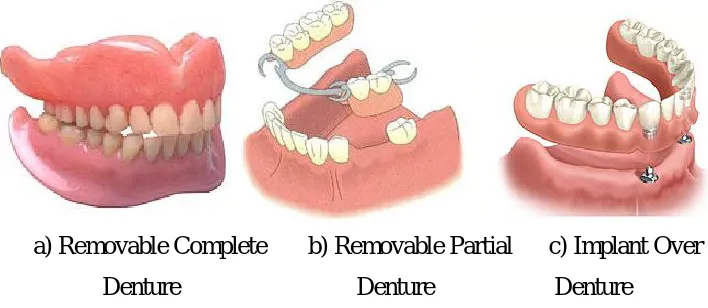
Denture is used to replace the damage, lost or removed tooth for human. There are few types of dentures which have been classified as removable complete denture or some time called as full denture, partial denture and over denture. The complete denture is used for people missing all teeth and the partial denture and over denture both are adaptations of the basic process in the removable complete denture. Reported from Malaysia Ministry of Health, in Malaysia have 3 millions denture user and among the highest in Asia. Where, about 58 percent is elderly more than 50 years (KKM, 2003). Currently, the elderly population those aged 60 and above has increased due to a longer life expectancy, the quality of life and better medical facilities (Ibrahim, 2011) . Following that, the denture demand has increased from year to year. Therefore, the development of complete denture was selected as a case study in this research. In addition, a new approach for denture fabrication was studied in order to solve some problems observed in the conventional technique.
2
(Yuchun Sun et al., 2009) and the integration of CAD/CAM & CNC for denture teeth fabrication (Chang and Chiang, 2002;Chang and Chiang, 2003). There was also a development in rapid manufacturing for implant framework directly using selective laser melting (SLM) by (McAlea et al., 1997;Gideon et al., 2003;Over et al., 2002). Although progress has already been reported elsewhere in the literature concerning the design and fabrication, significant gaps in knowledge are still existed. None is devoted to use vacuum casting technique for the fabrication process. Furthermore, this research also contributes in developing denture teeth set library which can be shared by any commercial CAD system.
1.2 Objectives of study
This study embarks on the following objectives;
i. To evaluate the process ability and mechanical properties of the existing denture material produced using vacuum casting and conventional technique. ii. To apply the dental principles in designing the removable complete denture
using computer aided design (CAD) system.
3
1.3 Scope of the study
The scopes of this study are;
i. Vacuum casting process was used as a manufacturing method to produce the removable complete denture.
ii. Cold cured or self cured acrylic resin was used as the denture base material. iii. Standard commercial denture teeth set were used in the denture system. iv. 3D-ATOS scanner system was used as digitizing device for edentulous
model, occlusion rims and denture teeth.
v. Commercial SolidWork CAD software was used in the virtual design and assembly.
vi. Multi Jet Modelling technology (ProJet SD3000) was used to produce denture model.
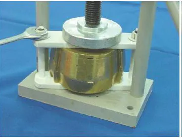
vii. MCP4-01, the vacuum casting machine was used in the rapid tooling fabrication process.
1.4 Problem statement
4
Therefore, an appropriate system is needed to solve the issues from the current process. The proposed idea is to use a computer system in the data acquisition, denture design and assembly as well as using the rapid tooling technique for the fabrication process.
1.5 Significant of study
5
1.6 Thesis outline
6
CHAPTER 2
LITERATURE REVIEW
2.1 Introduction
This chapter presents a literature review of conventional fabrication technique of removable complete denture as well as the advanced technique. It also reviewed the materials, tools and method that used in the denture fabrication process. In the advanced manufacturing technology (AMT), the basic principle of the layer manufacturing technology in rapid tooling (RT) and CAD were discussed.
2.2 Types of denture
7
cylindrically shape of pore titanium (Vecchiatini et al., 2009). Figure 2.1 shows the three types of denture.
[image:27.595.141.495.133.287.2]a) Removable Complete b) Removable Partial c) Implant Over Denture Denture Denture
Figure 2.1: Types of denture (Deadwood, 2008)
2.2.1 Removable complete denture
8
2.2.2 Parts of removable complete denture
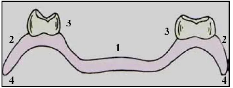
Removable complete denture has various parts and surfaces such as denture base (1), flange of denture (2), border of denture (3), denture teeth (3) and denture border as shown in Figure 2.2. Denture base is defined as part of a complete denture which rests on the oral mucosa and to which teeth is attached. It is usually made of acrylic resin. In some cases, the denture base made of metal is used to form the foundation of the denture. The denture base helps to distribute and transmit all the forces acting on the denture teeth to the basal tissues. It also has maximum influence on the health of the oral tissues. Moreover, it is the part of denture which responsible for retention and support (Veeraiyan et al., 2003).
The flange of a denture defined as the essentially vertical extension from the body of the denture into one of the vestibules of the oral cavity. It has two surfaces, namely, the internal basal seat surface and the external labial or lingual surface. The functions of the flange include, providing peripheral seal and horizontal stability to the denture. Other of that denture border defined as the margin of the denture base at the junction of the polished surface and the impression surface. It is responsible for peripheral seal. The denture border should be devoid of sharp edges and nodules to avoid soft tissue injury. Overextended denture borders can cause hyper-plastic tissue changes. On the other hand, the border should not be under extended as peripheral seal may be lost. Lastly, the denture tooth is the most important part of the complete denture from the patient’s point of view. The functions of the denture teeth are aesthetics, mastication and speech. They usually made from acrylic resin or porcelain (Veeraiyan et al., 2003).
9
Figure 2.2: Surface parts of a complete denture (1) Denture base (2) Denture flange (3) Denture teeth (4) Denture border (Veeraiyan et al., 2003)
2.3 Occlusal and teeth arrangment principles
10
2.4 Fabrication technique of removable complete denture
There are two type of removable complete denture fabrication technique known as conventional fabrication technique and advanced fabrication technique.
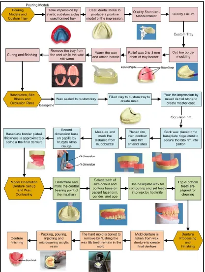
2.4.1 Conventional removable complete denture fabrication technique
Universities and private sectors have invested in carrying out research on denture fabrication technique. The technique divided into conventional technique and advance manufacturing technique. Intended, the method to forming denture base can see as the difference of denture fabrication technique. Nevertheless, the same procedures to each fabrication technique are used from earlier step until denture model process step which produced in dental lab. The denture process in conventional technique mostly involves first marking an impression technique on a patient’s mouth by a dentist. Then the impression is sending to the dental laboratory for fabrication a denture. At the laboratory, a dental technician cast a model of the mouth using impression from the dentist, making the cast model with composition called stone powder (Kamali, 2007).
11
[image:31.595.124.514.159.318.2]visit procedures as shown in Figure 2.3. The details of laboratory steps were simplified in process flow as shown in Figure 2.4.
12
13
2.4.1.1 Compression flask technique
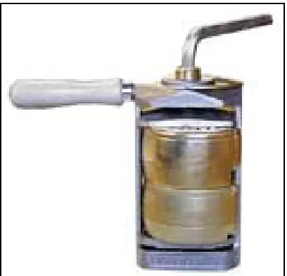
The compression flask technique is a type of conventional denture fabrication technique in which two sections of the flask are separated after the wax is removed from the flask. Then the cavities within the stone composition are formed with the prosthetic teeth held in the position hardened stone. Next, the cavity space has been packed with an acrylic resin composition from the dough form in between of two sections of the flask. Then, the flask has been positioned within a press to squeeze out all the excess acrylic resin compositions (Kamali, 2007).
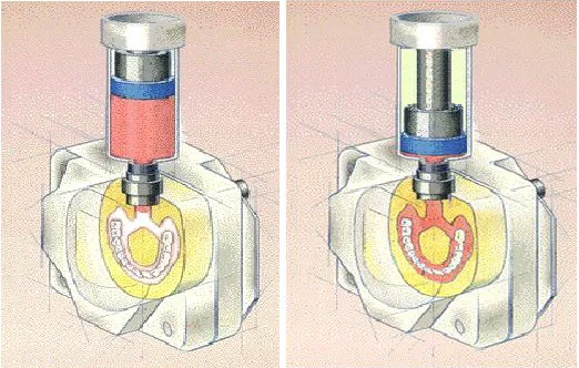
[image:33.595.217.424.463.662.2]Previous research found that the compression flask techniques was constituted to conventional flask closure and Rafael and Saide (RS) flask closure system as shown in Figure 2.5 and Figure 2.6 which the RS system had a smaller base distortion compares to conventional flask closure (Rafael et al., 2004). Then, the dimensional change more uniform when the denture are submitted to the 6 hour post-pressing time in RS flask closure method which these factors may reduce the magnitude of tooth movement (Wagner et al., 2009).
14
Figure 2.6: Rafael and Saide (RS) flask Closure (Rafael et al., 2004)
2.4.1.2 Injection moulding technique
15
Figure 2.7: Injection moulding technique (Apex, 2011)
2.4.2 Advanced technique of denture fabrication
A study from China presented a new method for fabricating the removable complete denture by computer-aided design and Rapid Prototyping (CAD& RP) technology. The special CAD software has been developed for the 3D integrated design process of denture. They were including to automatic setting up artificial teeth, semiautomatic designing aesthetic and individualized artificial gingival and base plate are automatic constructing individualized denture. Then 3DP technology was used to make the individualized physical flasks. Following this method, the complex process of traditional handicraft has cut down to relieve the workload and improve the restoration's accuracy (Yuchun Sun et al., 2009).
16
produced by Rapid Prototyping (RP) or Computer Numerical Control (CNC) machining methods based on the digital information (Chang et al., 2006).
2.5 Rapid prototyping, rapid tooling and rapid manufacturing technologies
[image:36.595.208.431.441.612.2]Countries around the world continue to adopt RP technology. Figure 2.8 shows the systems was sold and installed by country in 2002 (Wohlers, 2003). RP technology allows the production not only models and prototypes for visualization purposes, but also functional parts (Rosochowski and Matuszak, 2000) . The terms of rapid tooling and rapid manufacturing are subordinate to that of rapid prototyping. They were also related to special uses and application areas of rapid prototyping technology which it is a systematically and really technique (Willis et al., 2007).
17
2.6 Rapid prototyping basic principle
Basically, the rapid prototyping (RP) refers to the physical modelling of a design using digitally driven, additive processes. RP systems quickly produce models and prototype parts from 3D Computer Aided Design (CAD) data, Computed Tomography (CT) and Magnetic Resonance Imaging (MRI) scans, and data from 3D digitizing systems as shown in Figure 2.9 (Rosochowski and Matuszak, 2000).
[image:37.595.149.494.353.479.2]The RP systems join liquid, powder, or sheet materials to form physical objects. Through Layer by layer technique, RP machines process plastic, paper, ceramic, metal, and composites from thin, horizontal cross sections of a computer model.
Figure 2.9: Rapid prototyping basic principle (Rosochowski and Matuszak, 2000)
2.6.1 Rapid prototyping process chain
18
2.6.1.1 CAD model of the design creation
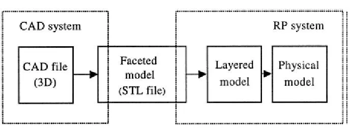
Several Computer Aided Design (CAD) software package may use in 3D model design such as Autocad, ProEngineer, SolidWork, Unigraphic and other things. Besides being able to generate 2D and 3D drawings, the CAD software is also can import another external solid and surface data file such as STL, IGES, STEP and so on (Sun et al., 2004). The external model as 3D surface from scanned devise such as 3D scanner (Willis et al., 2007) or computed tomography (CT) scan 9 (Caloss et al., 2007).
2.6.1.2 CAD model to STL format conversion
19
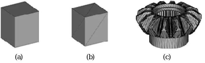
[image:39.595.145.498.74.183.2](a) (b) (c)
Figure 2.10: (a) A simple model, such as the box. (b) The box surfaces can be approximated with twelve triangles, two on each side. (c) More complex the
surface, the more triangles produced (Eden, 2009)
2.6.1.3 Slice the STL file into thin cross sectional layers
The pre-processing software slices the STL model into a number of layers in range 0.01 mm to 0.7 mm of thickness for rapid prototyping process. However, it has depended on the build technique. The program can be generated an secondary structure to support the model during the build. The slicing of large STL files could be generated the segments by laser or nozzle (Koc et al., 2000).
2.6.1.4 Layer construction
20
2.6.1.5 Cleaning or post processing
The final step is post-processing. This involves removing the prototype from the machine and detaching any supports. It essentially consists of part removal and cleaning and curing and finishing because some photosensitive materials need to be fully cured before use. Prototypes may also require minor cleaning and surface treatment. There will improve its appearance and durability. This step generally involves manual operations where an operator does the post processing with extreme care. Otherwise, the part may be damaged, and it needs to be prototyped again (Kai and Fai, 2003).
2.7 Rapid manufacturing
Rapid Manufacturing (RM) defined as the producing of end use products by using additive manufacturing techniques (solid imaging) (Rudgley, 2001). Another definition is the direct production of finished goods from a rapid prototyping (RP) device (Wohlers, 2003). The technique uses additive processes to deliver finished goods directly from digital data, which eliminates all tooling.
21
[image:41.595.193.447.154.315.2]manufacturing processes (Gideon et al., 2003;Kruth et al., 2003;Kruth et al., 2005). The technologies have been used in Rapid manufacturing shown in Table 2.1.
Figure 2.11: Produced frameworks by SLS/SLM from stainless steel (a, b) and from Ti6Al4V (c, d). Figure d shows the framework emerging from the powder (Kruth et
al., 2005)
Table 2.1: Technology Being Used for Rapid Manufacturing (Kai and Fai, 2003)
Plastic parts Metal parts Ceramic parts
*Selective Laser Sintering (SLS)
Related process;
-M3 (Concept laser GmbH) -RP3 (Speed part AB)
*Fused Deposition Modelling (FDM)
*Stereolithography (SLA) Related process;
-jetted photopolymer -spatial light modulator based exposure technologies
*MultiJet Modelling (MDM)
*Selective Laser Sintering (SLS) Related process;
-Selective Laser Metling (SLM) -Electron Beam Metling (EBM) -Arcam AB
*Laser powder forming includes; -Optomec LENS (TM)
-POM-Group DMD (TM) -Trumpf’s Direct Laser Forming (DFL)
*Three-dimennsional Printing (3DP)
*Sprayed metal includes; -Sprayform (Ford Global Technologies)
-Rapid Solidification process
[image:41.595.112.528.453.690.2]22
2.8 Rapid tooling (RT)
[image:42.595.129.519.315.664.2]Rapid tooling describes those applications that are aimed at making tools and moulds for the production of prototypes and pre-series by using the same processes as those used in rapid prototyping (RP). Another of that Rapid tooling is a progression from rapid prototyping which it is the ability to build prototype tools in contrast to prototype products directly from the CAD model resulting in compressed time to market solutions (King and Tansey, 2002). Figure 2.12 shows the comparison between rapid tooling and rapid prototyping in direct tooling.
Figure 2.12: Comparison of rapid prototyping to rapid tooling (King and Tansey, 2002)
Concept
CAD
Rapid Prototype
Mode
Rapid Prototype
Tool
Single master 1 part
Multi Models
500-1000part Rapid Tooling Route
Production process
23
2.8.1 Rapid tooling (RT) classification
[image:43.595.129.493.268.535.2]Figure 2.13 shows a classification of RT techniques such as pattern for casting, indirect tooling and direct tooling. In patterns for casting, it concentrating on producing patterns for the foundry industry. While for indirect tooling, it was used patterns for soft and hard tooling. Whereas for direct tooling, it was manufacture the tools directly on RP machines (Rosochowski and Matuszak, 2000;Nagahanumaiah et al., 2008).
Figure 2.13: Classification of RT (Rosochowski and Matuszak, 2000)
24
hard tooling methods facilitate fabricating metal tooling that can be used in injection moulding machines, and result in improved quality and larger quantity of parts compared to soft and bridge tooling (Nagahanumaiah et al., 2008).
Table 2.2: Important rapid tooling processes and their parent RP processes (Nagahanumaiah et al., 2008)
No Rapid Tooling
Process
Patent RP process Type of Rapid Tooling
Direct Indirect Soft Bridge Hard
1 SLA Direct-AIM SLA X X
2 SL EP 250 moulds SLA X X
3 SLS rapid steel SLS X X
4 Direct metal laser sintering
DMLS/SLS
X X
5 Direct shell production casting
3DP
X X
6 Prometal RT300 3DP X X
7 Metal laminated tooling
LOM
X X
8 Multi-metal layer tooling
SDM
X
9 SDM mould SDM
X X
10 Investment cast mould
SLA,FDM
X X X
11 3D Keltool SLA, Keltool X X
12 Spray metal tooling SLA, SLS, m/c
pattern X X
13 Vacuum Casting SLA, SLS, m/c
pattern X X
14 RP pattern base powder sintering
SLA, SLS
X
2.9 Development of rapid prototyping technology
[image:44.595.113.535.207.573.2]114
REFERENCES
KKM. (2003). Laporan Tahunan Kementerian kesihatan malaysia. 90-100. M. Ibrahim. (2011). Warga emas aset negara yang bernilai. Sinar harian.
Yuchun Sun, Peijun Lü and Y. Wang. (2009). Study on CAD&RP for removable complete denture. Computer methods and programs in biomedicine. 93(3).266-272. Issn: 0169-2607.
C.C. Chang and H.W. Chiang. (2002). Reconstruction the CAD model of complex object by abrasive computed tomography. In: Proc IEEE/ASME International Conference on Advanced Manufacturing Technologies and Education in the 21st Century. Taiwan. 11–14.
C.C. Chang and H.W. Chiang. (2003). Three-dimensional image reconstructions of complex objects by an abrasive computed tomography apparatus. The International Journal of Advanced Manufacturing Technology. 22(9).708-712. Issn: 0268-3768. doi: 10.1007/s00170-003-1571-8.
K. McAlea, P. Forderhase, Hejmadi and N. U., C. (1997). Materials and Applications for the Selective Laser Sintering Process. Proc. of the 7th Int. Conf. on Rapid Prototyping. San Francisco. 23-33.
N.L. Gideon, R. Schindel and J.P. Kruth. (2003). RAPID MANUFACTURING AND RAPID TOOLING WITH LAYER MANUFACTURING (LM)
TECHNOLOGIES, STATE OF THE ART AND FUTURE
PERSPECTIVES. CIRP Annals - Manufacturing Technology. 52(2).589-609. Issn: 0007-8506. doi: 10.1016/S0007-8506(07)60206-6.
115
parts and tools. Proc. of SME conf. on Rapid Prototyping and Manufacturing. Cincinnati.
S. Singla. (2007). Complete denture impression techniques: Evidence-based or philosophical. Indian Journal of Dental Research. 18(3).124-127. Issn: 0970-9290. doi: 10.4103/0970-9290.33788.
A. Pahlevan. (2005). A New Design for Anterior Fixed Partial Denture, Combining Facial Porcelain and Lingual Metal; PTU Type II. Journal of Dentistry of Tehran University of Medical Sciences. 2(3). Issn: 1735-2150.
R. Vecchiatini, N. Mobilio, D. Barbin, S. Catapano and G. Calura. (2009). Milled bar-supported implant overdenture after mandibular resection: a case report. Journal of Oral Implantology. 35(5).216-220. Issn: 1548-1336.
D. Deadwood. (2008). Denture Types. Retrienved December 2009. From: http://www.deadwooddental.com/partial.html.
D.N. Veeraiyan, K. Ramalingam and V. Bhat. (2009). Textbook of prosthodontics. 6th. ed., New Delhi: Jaypee Brothers. 4.
K. Robert. (2005). Personalized Processed Denture Bases. Dentures. Dental Lab Product. 28.
D.N. Veeraiyan, K. Ramalingam and V. Bhat. (2003). Textbook of prosthodontics. 1st. ed., New Delhi: Jaypee Brothers. 4-6.
S. Jambhekar, M. Kheur, M. Kothavadea and R. Dugal. (2009). Occlusion and Ocllusal Considerations in Impantology. Indian Journal of Dental Advancement. 2(1).125-127.
116
M. Kamali. (2007). Denture flask compress tool and process. US Pat. No. 7413426B2.United State Patent.
K. Yasuhiko, M. Hiroshi, S. Batoul, K. Esa, B.J. V., B. Lucie, L.J. P. and F.J. S. (2005). Do traditional techniques produce better conventional complete dentures than simplified techniques. Journal of Dentistry. 33(8).659-668. Issn: 0300-5712.
L.X. Rafael, S.S. Domitti, M.F. Mesquita and S. Consani. (2004). Effect of packing types on the dimensional accuracy of denture base resin cured by the conventional cycle in relation to post-pressing times. Braz Dent J. 15(1).63-7.
A. Wagner, L.X. Rafael, F. Marcelo, A.C. Mario and I. R. (2009). Effect of Flask Closure Method and Post-Pressing Tie on the Displacement of Maxillary Denture Teeth. The Open Dentistry Journal. 3.21-25.
M. Handler. (2009). Conventional denture flask. Retrienved From: www.handlermfg.com/web/index.php?main_page=in.
H. Kimura, F. Teraoka and M. Sugita. (1990). Application of microwave for dental technique. 5. Injection molding system for resin base denture]. Shika zairy , kikai= Journal of the Japanese Society for Dental Materials and Devices. 9(1).74. Issn: 0286-5858.
H. Kimura, F. Teraoka and M. Sugita. (1991). The Production of Acrylic Denture by Injection Molding Method: (Part 1)Relationship between Additional Pressure and Adaptability of Denture. Journal of the Japanese Society for Dental Materials and Devices. 10(3).404-409.
117
D. Apex. (2011). Injection Moulding. Apex Dental Lab. 2009 Retrienved From: http://apexdental.com.au/dentures.html.
C. Chang, M. Lee and S. Wang. (2006). Digital denture manufacturing-An integrated technologies of abrasive computer tomography, CNC machining and rapid prototyping. The International Journal of Advanced Manufacturing Technology. 31(1).41-49. Issn: 0268-3768. doi: 10.1007/s00170-005-0181-z.
T. Wohlers. (2003). State of the Industry and Technology Update. Rapid Prototyping Report. Wohlers Associates Inc. EuroMold.
A. Rosochowski and A. Matuszak. (2000). Rapid tooling: the state of the art. Journal of Materials Processing Technology. 106(1-3).191-198. Issn: 0924-0136.
A. Willis, J. Speicher and D.B. Cooper. (2007). Rapid prototyping 3D objects from scanned measurement data. Image and Vision Computing. 25(7).1174-1184. Issn: 0262-8856.
W. Sun, B. Starly, A. Darling and C. Gomez. (2004). Computer aided tissue engineering: application to biomimetic modelling and design of tissue scaffolds. Biotechnology and applied biochemistry. 39(1).49-58. Issn: 1470-8744.
R. Caloss, K. Atkins and J.P. Stella. (2007). Three-Dimensional Imaging for Virtual Assessment and Treatment Simulation in Orthognathic Surgery. Oral and Maxillofacial Surgery Clinics of North America. 19(3).287-309. Issn: 1042-3699.
C.M.S. Etomite. (2007). STL 2.0 May Replace Old, Limited File Format. Rapid
Publishing. Retrienved September 2009. From:
118
P. Eden. (2009). Guide to quality STL files. . RedEye On Demand. . USA. 1-7.
B. Koc, Y. Ma and Y.S. Lee. (2000). Smoothing STL files by Max-Fit biarc curves for rapid prototyping. Rapid Prototyping Journal. MCB UP Ltd. 186-205.
W. Palm. (2002). The Basic Process. Rapid Prototyping primer. Penn State. 2. C.C. Kai and L.F. Fai. (2003). Rapid prototyping: principles and applications in
manufacturing. 2nd. ed., Vol. 3: World Scientific.
M. Rudgley. (2001). Rapid manufacturing-the revolution is beginning. Proceedings of the uRapid Amsterdam, Netherlands. 441-444.
J.P. Kruth, P. Mercelis, J. Van Vaerenbergh, L. Froyen and M. Rombouts. (2003). Advances in Selective Laser Sintering. Proc. of the 1st Int. Conf. on Advanced Research in Virtual and Rapid Prototyping (VRAP2003). Leiria. 1-4.
J.P. Kruth, B. Vandenbroucke, J. Vaerenbergh and I. Naert. (2005). Rapid manufacturing of dental prostheses by means of selective laser sintering/melting. Proceedings of the 2nd International Conference on Advanced Research in Virtual and Rapid Prototyping. Leiria,Portugal. 9.
D. King and T. Tansey. (2002). Alternative materials for rapid tooling. Journal of Materials Processing Technology. Elsevier. 313-317.
Nagahanumaiah, K. Subburaj and B. Ravi. (2008). Computer aided rapid tooling process selection and manufacturability evaluation for injection mold development. Computers in Industry. 59(2-3).262-276. Issn: 0166-3615. doi: 10.1016/j.compind.2007.06.021.
119
E.M. Donald. (2005). Multi Jet Modelling. The New York Times Company (NYSE: NYT). Retrienved From: http://metals.about.com/library/weekly/aa-rp-mjm.htm.
Z.J. Czajkiewicz. (2008). Direct Digital Manufacturing-New Product Development and Production Technology. Economics and Organization of Enterprise. 2(2).29-37. Issn: 0860-6846. doi: 10.2478/v10061-008-0016-8.
R. Ramsdale. (2006). Rrapid Prototyping;MultiJet Modelling. EngineersHandbook.com. Retrienved December 2009. From: http://www.engineershandbook.com/RapidPrototyping/mjm.htm.
S. Rock Hill. (2008). 3D SYSTEMS CORPORATION. (NASDAQ: TDSC).
P. Tuteleers, A. Kirk, M. Chateauneuf, H. Ottevaere, V. Baukens, C. Debaes, M. Vervaeke, A. Hermanne, I. Veretennicoff and H. Thienpont. (2005). Investigation of the replication quality of plastic micro-optical interconnection components. Proceedings of the 6th Annual Symposium IEEE/LEOS Benelux Chapter. Department of Applied Physics and Photonics (TW-TONA).
Protosys. (2005). Vacuum Casting. Protosys Technologies Pvt. Ltd. Retrienved June 2010. From: http://www.protosystech.com/rapid-tooling.htm.
G.K. Mais. (1991). Process parameters for the casting of quality products under vacuum. Electrical Electronics Insulation Conference, 1991. Boston '91 EEIC/ICWA Exposition., Proceedings of the 20th. Boston, MA , USA 230-235.
120
S.E. Park, M. Chao and P.A. Raj. (2009). Mechanical properties of surface-charged poly (methyl methacrylate) as denture resins. International Journal of Dentistry. 2009.6. Issn: 1687-8728. doi: 10.1155/2009/841431.
A. Usanmaz, M.A. Latifoğlu, A. Doğan, N. Akkaş and M. Yetmez. (2002). Mechanical properties of soft liner–poly(methyl methacrylate)-based denture material. Journal of Applied Polymer Science. 85(3).467-474. Issn: 1097-4628. doi: 10.1002/app.10338.
D. Radford, W. T, W. J and C. S. (2009). The effects of surface machining on heat cured acrylic resin and two soft denture base materials: a scanning electron microscope and confocal microscope evaluation. The Journal of Prosthetic Dentistry. 78(2). 200-208.
Shin-Etsu. (2002). Making a Silicone Rubber Mold. RTV Silicone Rubber for Moldmaking. Shin-Etsu. Japan. 14-15.
K.J. Anusavice. (2003). Science of Dental Materials. 11th ed. ed., MO: Saunders: St Louis.
H.-K. Tan, J.S. Brudvik, J.I. Nicholls and D.E. Smith. (1989). Adaptation of a visible light-cured denture base material. The Journal of Prosthetic Dentistry. 61(3).326-331. Issn: 0022-3913.
C. Machado, E. Sanchez, S.S. Azer and J.M. Uribe. (2007). Comparative study of the transverse strength of three denture base materials. Journal of Dentistry. 35(12).930-933. Issn: 0300-5712.
O. Gurbuz, F. Unalan and I. Dikbas. (2010). Comparison of the transverse strength of six acrylic denture resins. 6.21-24.
121
DeguDent. (2009). Rapid repair. Dentsply International. Retrienved March 2010. From: http://www.degudent.com/Products/Denture_Bases/Rapid_Repair.asp.
I.L. Ali, N. Yunus and M.I. Abu-Hassan. (2008). Hardness, Flexural Strength, and Flexural Modulus Comparisons of Three Differently Cured Denture Base Systems. Journal of Prosthodontics. 17(7).545-549. Issn: 1532-849X. doi: 10.1111/j.1532-849X.2008.00357.x.
S.H. Tuna, F. Keyf, H.O. Gumus and C. Uzun. (2008). The Evaluation of Water Sorption/Solubility on Various Acrylic Resins. European Journal of Dentistry. 2.191-197.
R. Taggart. (2008). Desktop Engineering readers select Geomagic Studio 10 as top product. Research Triangle Park. Geomagic Inc.
A.O. Rahn and J.R. Ivanhoe. (2009). Textbook of complete dentures. 6th. ed., USA: Pmph USA Ltd. 142.
Weine F. S., C.G. Kenneth, A.W. Lawrence and G. Arnett. (1991). Dental course. Homestead School, Inc. Retrienved July 2010. From: http://www.homesteadschools.com/dental/courses/Anatomy/Chapter2.htm.
D.N. Veeraiyan. (2003). Textbook of Prosthodontics. 1st. ed., New Delhi: Jaypee Brother Medical. 199-201.
K.D. Rudd, R.M. Morrow and J.E. Rhoads. (1986). IMMEDIATE DENTURES. 2. ed. R.M. Morrow, Vol. 1: Mosby.
U. Moenckmeyer. (2003). Debture Set. US 6533581B1.US patent.
122
C.C. Kuo and M.L. Lai. (2011). Developement of an automatic degassing system and parameters optimization for degassing process. Indian Journal of Engineering & Materials Sciences. 18.405-410.
S. Upcraft and R. Fletcher. (2003). The rapid prototyping technologies. Assembly Automation. 23(4).318-330. Issn: 0144-5154.
S.E. Smith. (2011). What is an Articulator. wiseGEEK. Retrienved From: http://www.wisegeek.com/what-is-an-articulator.htm.
M. Tatum and B. Harris. (2011). What is Manufacturing Cost. wiseGEEK. Retrienved From: http://www.wisegeek.com/what-is-manufacturing-cost.htm.
M.A. Rahman. (2007). Senarai harga rawatan yang disyorkan oleh persatuan Doktor-doktor gigi Malaysia. Retrienved April 2010. From:
http://drleen.wordpress.com/2009/11/18/senarai-harga-rawatan-yang-disyorkan-oleh-persatuan-doktor-doktor-gigi-malaysia/.