Abstract—A Smart Label for theses management in Resource Centre of Faculty of Electrical and Electronics Engineering (FKEE), UTHM is being developed using Radio Frequency Identification (RFID). The smart label is developed to improve the existing theses management and loan system in FKEE Resource Centreand to reduce the time consumes by a student to find the theses. It consists of a portable module and RFID reader and tags that operates at frequency range of 13.56MHz. Theses informations such as title, authors and shelf number will be programmed into the RFID transponder. A database system which developed using Visual Basic 6.0 allows the students to search the list of theses and the theses informations. RFID reader then exchanges the data between transponder and the interface program. RFID tag sends electromagnetic waves that induce current in the tag’s antenna when it is in the reader zone. The tag reflects to the RF signal transmitted and adds information by modulating the reflected signal. Therefore, the system is able to detect the tags and student could easily find the location of the theses.
Keywords: Smart Label, RFID tag, reader, theses, database.
I. INTRODUCTION
FID is often presented as a replacement for today’s barcodes, but the technology has much greater possibilities, such as individual serial numbers for each item, and the possibility to read these numbers at a distance of several metres [1]. Recently, many libraries have become aware and put their interests on RFID application to manage and organise their collections. Such invention relates to a system and method of handling the inventory of materials available and check-out items in a library by using RFID technology to gather data from RFID tags on library items and transmit that data to the active focus of an application. Data such as item’s identification (ID) number, title, and author can be stored into the tags. As such, a library system is developed for book list mode and single book mode in [2]. Besides, a study has been conducted in [3] to measure the performance of RFID library system at a university library by examining factors, namely tag placement, reader orientation sensitivity, read rate, reading distance, and metal and electromagnetic interference.
Based on [2], [3] and taking the advantages of RFID technology, a Smart Label for theses management in FKEE Resource Centre, UTHM is being developed. FKEE Resource Centre is actively supports the teaching and learning activities and provides a space for the students in the faculty to revise or borrow the theses which are located here. Students have to check the theses ID number and the lab assistant has to assist them searching for the theses. As the number of thesis keeps expanding in each semester and more students need to be served, such system is ineffective assist many students at a time. Hence, Smart Label is an alternative to help students to find the thesis of their interest more easily and for the lab assistant to manage the theses collection in FKEE Resource Centre.
II. HARDWARE & SOFTWARE
The Smart Label development consists of an RFID system and graphical user interface (GUI) developed using Visual Basic 6.0. Primarily, the two main components involved in RFID system are the transponder (the tags that attached to an antenna) and the interrogator (RFID reader) [2]. In figure 1, the transponder is affixed to the thesis that is to be tracked or identified within the supply chain by the RFID system. The reader has a number of varied responsibilities including powering the transponder, identifying, read/write data from/to it, and communicates with a data collection application. Then, data collection application receives data from the reader, enters the data into a database in computer, and provides access to the data in a number of forms that are useful to the sponsoring organization. We can define frequency as the transfer data rate (speed) between the reader and tag takes place. If the reader and tag operate at the low frequency, the transfer data rate between tag and reader are also slow.
Development of Smart Label Using RFID to
Manage and Organize Theses Collection in
FKEE Resource Centre
Warsuzarina Mat Jubadi, Mohd. Nazrulhafizi Halban and Rafidah Rosman
R
Proceedings of EnCon2008 2nd Engineering Conference on Sustainable Engineering
Infrastructures Development & Management December 18 -19, 2008, Kuching, Sarawak, Malaysia
Figure 1:Basic principle of RFID components. A. RFID Tag (Transponder)
RFID tags (transponder) can be divided into passive tag and active tag. Passive tags were selected to be used in the system by taking the advantages of its smaller size, lighter weight, requires no power source, and less expensive than those that is active. It originates operating power from the electrical field generated by the reader. These transponders are only activated when within the response range of a reader. The RFID reader emits a low-power radio wave field which is used to power up the tag so as to pass on any information that is contained on the tag [4]. The passive RFID tags have an induced antenna coil voltage for operation because it did not have external power source. This antenna can induce AC voltage when energizing RF signal is provided to provide a voltage source for the device on the tag. As the DC voltage reaches a certain level, the device start operating. So, an RFID reader can communicates with a remotely located device [5].
B. RFID Reader
An RFID reader typically contains a transmitter and receiver module. It also has a control unit and a coupling element (antenna) to the transponder. The reader has three main functions; energizing, demodulating and decoding. It can read and receive the data, and then forward it into another system such as a computer, robot control system, and etc. Reader is functioned to read data stored on the tag or write data into the tag. This function are very useful because with a read/write tag, the data can be changed, added to, or even eliminated at any point during it lifecycle [5].The reader also can be fitted with an additional interface such as RS 232 or RS 485 that converts the radio waves returned from the RFID tag into a form that can be passed on to another system like a computer [6]. The RFID reader used in the project is shown in figure 2.
Figure 2: The 13.56MHz RFID reader used in the Smart Label Development C. Database and Interface System
A database and interface systems are required to make sure the thesis detection is available. A database system stores the theses information’s such as title, author, year and shelf number. The database can only be accessed through the interface programme which designed to collect the theses informations. In this project, a Graphical User Interface (GUI) using Visual Basic is developed to allow user to communicate with the administrator and hardware. Visual Basic allows the programmer to create, run, and debug windows programs in one application without the need to open additional. Visual Basic is a visual and events driven programming language. There are few steps in order to create the interface as required below:
i. Design background of GUI. Define each function that needs to design. ii. Create a new GUI using Microsoft Visual Basic 6.0.
iii. Combining all the important components inside the GUI that was created. iv. Write a program for the interface.
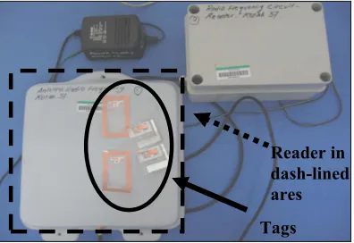
Tags Reader in dash-lined ares
[image:2.595.205.403.424.560.2]
RFID tag Antenna RFID
reader III. SYSTEMDEVELOPMENT
[image:3.595.211.395.125.226.2]This project has been divided into two parts; hardware and software programming. The hardware development deals with the RFID tags and reader and computer system whiles the database and interface systems were programmed using Visual Basics and Microsoft Access. Figure 3 shows the overall system of Smart Label development which communicates the RFID tags, reader and the database system.
Figure 3: Overall System of Smart Label
A. Hardware Development
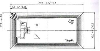
[image:3.595.220.391.351.439.2]Hardware is the most important element to ascertain the project works smoothly. A transponder is a combination of a microchip which carries data and the antenna which enables the energy and data transfer. Figure 4 illustrates the RFID transponder used to store the data of the registered theses and a rectangle transponder is used with the size of 76.0mm x 45.0mm and certified by ISO 15693-2-3. This transponder is programmed to store the theses information data using GUI forms which developed by administrator.
Figure 4: RFID transponder used in the system
As mentioned in previous section, RFID reader allows data exchange between transponder and the interface program. When the tag is in a reader zone, it sends electromagnetic waves that induce current in the tag’s antenna. The tag reflects the RF signal transmitted and adds information by modulating the reflected signal. Therefore, it alerts the user and student or the lab assistant could easily find the location of the thesis. For the system development, the read/ write reader from RF-IDENT Company was used. RF-IDENT reader operates at 13.56MHz frequency.
When user searches the theses they interested with, the reader, through its antenna system will read information from RFID tag and transfer it to the RFID reader. This system used 13.56 MHz radio frequency to communicate with the RFID tag and reader. The figure 5 shows the block diagram of how RFID tag and RFID reader communicates to each other through an antenna system.
Figure 5: Communication between RFID tag and reader
[image:3.595.178.410.595.630.2]
Database for the system
Find at what shelf the thesis is placed
Student search the book by using computer system Computer
system (GUI &
Figure 6: Function of computer system. B. Software Development
Using Visual Basic 6.0, a Graphical User Interface (GUI) had been developed. The GUI forms are designed as to link the user, administrator and the RFID system. There are several forms designed to allow the user to search for the theses informations. There are Search Form, Detail Form, Register Menu Form, and RFID Tag Sensor Form. Each of these forms is interrelated and linked to each other.
(i) The Main Form is the main window of the interface system. This window will be linked with another form so that the user can select which part they want to do next.
(ii) The Search Form is the vital part that was designed. Student who wants to find the book need to insert the keyword such as thesis title in the Search Form box.
(iii) After the search button is clicked, Detail Form will appear on the screen. Detail Form consists of data that will help student to find the thesis. From this form, student will know the location and shelf where the thesis is placed. There are few informations appears in the DetailForm such as Book Title, Shelf, Author, and Year.
(iv) Failed Form appears when the system failed to pool the information from Detail Form. For example, if the user gives the wrong keyword in Search Form, Fail Form will appear on the screen. Then, the user need to enter another keyword so that the system can find the data for that thesis.
(v) Register Menu Form is used to store the data into RFID tag. It consists of several types of Command Button such as Write Tag Command Button and Read Tag Command Button where these buttons have the characteristic to read and store the data. By using this form, user need to key in thesis ID, title, and other information that needed. After that, Write Tag command button is used to write and store the data into the tag while Read Tag Command Button is used to read all the data that stored in the tag.
A database system was also developed using Microsoft Access to interface with the GUI forms. It helps the students to search the list of theses, thesis ID number and shelf of the thesis placed. Microsoft Access and is linked with Visual Basic to make an application. Both of this software has a high interact to be used together. Table 1 lists the attributes of the database system. The function of database table is to save the information data that has been taken from Microsoft Visual Basic interface.
Table 1 Attributes of table in Microsoft Office Access 2003.
Table Function Field =ame Data Type
Database Save thesis b_id(Primary Key) Text
information b_title Text
b_author Text
b_year Text
shelf_no Number
IV. RESULT & ANALYSIS
The framework of the Smart Label application as a theses management system in FKEE Resource Centre is discussed here. Both software and hardware testing have been carried out to ensure both systems can be interfaced to each other.
A. Software Testing
Table 2 Sample of Main Database created using Microsoft Access
THESIS ID TITLE AUTHOR YEAR SHELF 2007/B-001 Robot kenderaan kawalan jauh dan
automatik
Ahmad Syakir Mohd Salim
2007 A 2007/B-002 Can-based GPS modular system Ain Nazari 2007 A 2006/B-126 Designing Broadband Microstrip
Antenna For 3G Application
Viganeswari A/P Logvinayaga
2006 B 2006/B-133 An Obstacles Avoidance Mobile Robot Zuraidah
Ahmad
2006 B 2006/B-136 Pulsed Elektromagnetic Field Simulator Aizuriza Ab
Aziz
2006 B 2006/A-053 Brainwave Synchronizer Norhalimatus
Saadiah Awang Salleh
2006 C 2005/B-006 Power line monitoring Ahmad Farid
Abdul Rahman
2005 C 2005/B-005 Digital control design for the boiler
drum
Afrodi Ali 2005 C 2007/B-063 Two wheel robot : obstacles avoidence Yussamsuriad
i Mad Yunus
[image:5.595.175.423.268.371.2]2007 D
Table 3 Database Table which links to the interface forms
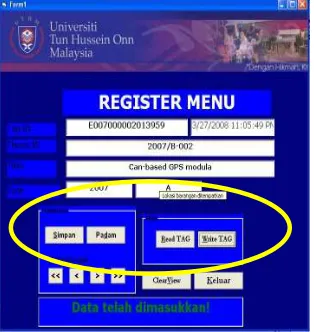
[image:5.595.224.381.467.633.2]Figure 7 shows the result of GUI developed by using Visual Basic. It shows the Interface Form register. All the blocks and icons in the circle are set to be invisible when the system runs. The functions of the blocks and icons are set to read and write the RFID tag. If the user clicks on the Read Tag command button, the reader will read all the data that stored in the tag. Write Tag command button is used to write data into the RFID tag. A successful message box will appear if the writing process is successful.
Figure 7: Interface example of storing data into an RFID tag. User need to key-in thesis ID, title, and other information that needed.
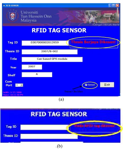
The RFID Tag Sensor forms allow the user to see if the RFID reader detects the information from the tag. This form acts as a sensor and detects RFID tag that placed inside the cover of the thesis. This form must be linked with the hardware as long as it’s function to detect the thesis. The sensor checkbox must be checked to allow the reader detects RFID tags on its range.
(a)
(b)
Figure 8: (a) Interface form when no tag is detected by the reader. (b) Interface form if the tag is in reader’s range.
B. Hardware Testing
The interface program is used to test the connection between the RFID reader and the system. The hardware is connected to the system by the RS232 serial port. The system is programmed to automatically open or activate the RFID reader and receives data written on the tag. The Smart Label development uses RFID reader to communicate with RFID tag. When the reader is passed through the thesis that locates an RFID tag, the antenna read the data from the tag. RFID antenna sends the data from the RFID tag to RFID reader. Then, the reader sends the data by using RS232 port to a computer terminal. As a result, the data will show the thesis information’s and where it is placed.
V. CONCLUSION
The Smart Label development is a new application of RFID in this university. The results and analysis discussed in previous subtopic proofs that the objectives have been achieved. The thesis informations were successfully stored and detected using RFID reader/tags at 13.56 MHz frequency. The interfacing between RFID system and the database is successfully performed. Therefore, students are able to use the Smart Label system and locate the required thesis on the shelves easily. As for the lab assistant, it helps to manage and organise the theses collection on her own. However, the interfacing problems might occur if reader cannot work properly and fails to detect the tags. For future work, this project still needs some improvements in order to achieve an efficient theses management and loan process system. For example, one might want to upgrades the system capability by adding more functions at the GUI and develope an RFID bookdrop system. Thus, user can return the theses after the office hour.
VI. REFERENCES
[1] Jan H.H.Mortensen T.A.Pedersen, ”Possible Use of RFID Technology in Support of Construction Logistics,” Graduate thesis, Master of Information and Communication Technology, Agder University College, 2004.
[2] Kuen-Liang, Yi-Min Lo, Kuen-Liang Sue and Yi-Min Lo, “BLOCS: A Smart Locating System Based on RFID in “BLOCS: A Smart Book-Locating System Based on RFID in Libraries,”Master thesis, Dept. Elect. Eng.
[3] Paul Golding ,Vanesa Tennant,” Work in Progress: Performance and Reliability of Radio Frequency Identification (RFID) Library System,” International Conference on Multimedia and Ubiquitous Engineering (MUE'07), 2007.
[4] Finkenzeller, Klaus,” RFID Handbook: Radio-Frequency Identification Fundamentals and Applications,” John Wiley & Sons, Ltd., USA, 1999, pp 25 - 32.
[5] Shepard, Steven,” RFID: Radio Frequency Identification,” McGraw-Hill,2005, pp 55 - 63.
[6] Manish Bhuptani and Shahram Moradpour, “RFID Field Guide: Deploying Radio Frequency Identification Systems,” Prentice Hall, 2005, pp 36 – 49.
[7] Mitchell C.Kerman, Ronald L.Brown, “Computer Programming Fundamentals with Application inVisual Basic 6.0” Addison Wesley Longman, Inc, 2000.
[image:6.595.200.414.45.304.2]