B03P-5325-0100A ... 028
M244X
Series
Streaming Tape Drive
CE Manual
cO
01 May, 1985 02 Feb., 1988 02A May, 1988
026 May, 1989
All pages revised.
Editorial Changes, I, tii, vi, 6·2, 6·4, 6-8, 6·9, 6·12, 6-38, 7·6, 1·1
Editing
Specification No.: 903P·5325-0100A
The contenls ol this manual are subied to change - prior notice. AttRighfsReseMld,
FAI Copyrigh1©1985,1988 FUJITSU LIMITED.
Commen1s-ng lhlsmanual shoc.tld be addressed to oneal1hefol-.g addresseS:
FB94123
FUJITSU LIMITED l,,_.tional Mad<e!ing
Marunouc:N 1-6-1, Chiyoda-ku, Tokyo 100JAPAN TEL: 03-216-3211
FAX: 03-213-7174, 03-216-9353
TI.X: J22833
Cable: "FUJITSU LIMITED TOKYO" FUJITSU AMERICA INC.
3055 On:hard Drive, San Jose,~ 9513'"2017, U.S.A. TEL: (1-408) 432·1300
FAX: 408-432·1318, 1319 TLX: 230-176207 TWX: 910-338-2193
FUJITSU CANADA INC.
6280 Nonhwest Drive, Mississauga, Toron10, On1ario, CANADA TEL: (1-416) 673-8666
FAX: 416-673-86n
TL.X: 968132 FUJITSU EUROPE LIMITED 2, Longwatk Road, ~ Park, West Drayton, Middteoex U811 1AB, ENGLAND TEL: (44·1) 573-4444
FAX: 1·573-2643 TLX: 263871FEL SP G
FUJITSU DEUTSCHLAND GmbH
Rosen,'leimefstlaBe 145, ~ Monchen 80, F.R. GERMANY TEL: (49-89) 413010
FAX: mM1301100 TLX: 897106 FOG 0
FUJITSU NORDIC l>B
TOf911111an 8, 171 54, Sotna, SWEDEN TEL: (46) ll-764·7MO FAX: 8-28-03-45
TI.X: 13411 FNAB S FUJITSU ITALIA S.p.A.
Via Melchione Gioia, 8, 20124 M4ano, ITALY TEL: (39-2) 6572741
FAX: 2-6572257
TLX: 350142FJJTLY I FUJITSU AUSTRALIA LIMITED
41 Mc1.an!n 51reet. Nor1h s,dney, N.S.W. 2060. AUSTRALIA TEL: (61-l!) 959-6555
FAX: 2-922-2653 TI.X: 25233
FUJITSU HONG KONG LIMITED
R.M. 1831, Sun Hung Kai Centre, 30 Hmbaur Road, HONGKONG
TEL: (652-5) 8915780
FAX: 5-742917
LIST OF EFFECTIVE PAGES
PAGE REV PAGE REV PAGE REV PAGE REV PAGE REV PAGE REV PAGE REV
Cover 02B 4-5 02B 4-37 02 5-9 02 6-1 02 6-33 02 B-3 02
Blank
-
4-6 02 4-38 02 5-10 02 6-2 02A 6-34 02 B-4 02i 02B 4-7 02 4-39 02 5-11 02 6-3 02 6-35 02 C-1 02B
Blank - 4-8 02 4-40 02 5-12 02 6-4 02A 6-36 02 Blank
-iii 02B 4-9 02 4-41 02 5-13 02 6-5 02 6-37 02 Reader
Blank
-
4-10 02 4-42 02 5-14 02 6-6 02 6-38 02A Comment Card-v 02 4-11 02 4-43 02 5-15 02 6-7 02 6-39 02B Blank
-vi 02A 4-12 02 4-44 02 5-16 02 6-8 02B 6-40 02 Cover
-vii 02 4-13 02 4-45 02 5-17 02 6-9 02A 6-41 02
Blank
-
4-14 02 4-46 02 5-18 02 6-10 02 Blank-1-1 02 4-15 02 4-47 02 5-19 02 6-11 02 7-1 02
1-2 02 4-16 02 4-48 02 5-20 02 6-12 02A 7-2 02
1-3 02 4-17 02 4-49 02 5-21 02 6-13 02 7-3 02
1-4 02 4-18 02 4-50 02 5-22 02 6-14 02 7-4 02
2-1 02 4-19 02 4-51 02 5-23 02 6-15 02 7-5 02
2-2 02 4-20 02 4-52 02 5-24 02 6-16 02 7-6 02A
2-3 02 4-21 02 4-53 02 5-25 02 6-17 02 7-7 02A
2-4 02 4-22 02 4-54 02 5-26 02 6-18 02B 7-8 02
2-5 02 4-23 02 4-55 02 5-27 02 6-19 02 7-9 02B
2-6 02 4-24 02 4-56 02 5-28 02 6-20 02 7-10 02B
2-7 02 4-25 02 4-57 02 5-29 02 6-21 02B A-1 02
2-8 02 4-26 02 4-58 02 5-30 02 6-22 02 A-2 02
2-9 02B 4-27 02 4-59 02 5-31 02 6-23 02 A-3 02
2-10 02 4-28 02 4-60 02 5-32 02 6-24 02 A-4 02
2-11 02 4-29 02 5-1 02 5-33 02 6-25 02 A-5 02
Blank
-
4-30 02 5-2 02 5-34 02 6-26 02 A-6 023-1 02 4-31 02 5-3 02 5-35 02 6-27 02 A-7 02
3-2 02 4-32 02 5-4 02 5-36 02 6-28 02 A-8 02
4-1 02 4-33 02 5-5 02 5-37 02 6-29 02 A-9 02
4-2 02 4-34 02 5-6 02B 5-38 02 6-30 02 A-10 02
4-3 02 4-35 02 5-7 02 5-39 02 6-31 02 B-1 02
CONTENTS
CHAPTER 1 GENERAL DESCRIPTION •••••••••••••••••••••••••••••••••••••• 1-1
1.1 General Description • • • • • • • • • • • • • • • • • • • • • • • • • • • • • • • • • • • • • • 1-1
l. 2 Configuration •••••••••••••••••••••••••••••••••••••••••••• 1-1
l. 3 Specifications • • • • • • • • • • • • • • • • • • • • • • • • • • . • • • • • • • • • • • • • • • • 1-1 l.3.1 Functional specifications ••••••••••• . . . 1-1 l.3.2 Physical specifications • , ••••••••••••••••••••••••••••• 1-2 1.3.3 Reliability and maintenablity ••••••••••••••••••••••••• 1-2 1.4 Recording Method . . . 1-3 1.4. l Phase Encoding format . . . 1-3 1.4.2 Group Coded Recording format •••••••••••••••••••••••••• 1-3
CHAPTER 2 INSTALLATION • • • • • • • • • • • • • • • • • • • • • • • • • • • • • . • • • • • • • • • • • • • • • 2-1 2. 1 Unpacking • • • • • • • • • • • • • • • • • • • • • • • • • • • • • • • • • • • • • • • • • • • • • • • • 2-1 2.1.l M2441/M2443 ••••••••••••••••••••••••••••••••••••••••• •• 2-1 2. l. 2 M2442/M2444 • • • • • • • • • • • • • • • • • • • • • • • • • • • . • • • • • • • • • • • • • • • 2-2 2.2 Mechanical Installation . . . 2-4 2.2.l M2441/M2443 installation . . . 2-4 2.2.2 M2442/M2444 installation . . . 2-5 2.3 Cable Connection . . . 2-8
2.3.1 Interface cable and power cable •••••••.••••••••••••••• 2-8
2.4 Checkout ••••••••••••••••••••••••••••••••••••••••••••••••• 2-9
2.4. l Input voltage setting . . . 2-9 2.4.2 Device address & Write bus parity check setting ••••••• 2-9 2.4.3 Setting by Operator Panel ••••••••••••••••••••••••••••• 2-11 2.5 Diagnostics . . . 2-11
CHAPTER 3 OPERATION • • • • • • • • • • • • • • • • • • • • • • • • • • • • • • • • • • • • • • • • • • • • • • • • 3-1
3.1 Power ON/OFF switch •••••••.•••••••••••••••••••••••••••••• 3-1
3. 2 Operator Panel . . . 3-1 3.2.1 Start key and indicator .•••••••••••••••••••••••••••••• 3-1 3.2.2 Unload key and indicator •••••••••••••••••••••••••••••• 3-1 3. 2. 3 Test key and indicator . . . 3-1 3.2.4 Reset key ••••••••••••••.•••••••••••••••••••••••••••••• 3-1 3.2.5 Density Select key •••••••••••••••••••••••••••••••••••• 3-2 3.2.6 File protect indicator •••••••••••••••••••••••••••••••• 3-2 3.2.7 Density indicators (HOST/6250/1600) ••••••••••.•••••••• 3-2 3.2.8 2-Digit indicator •.••••••••••••••••••••••••••••••••••• 3-2
CHAPTER 4 THEORY OF OPERATION • • • • • • • • • • • • • • • • • • • • • . • • • • • • • • • • • • • • • • 4-1 4. 1 Mechanism • • • • • • • • • • • • • • • • • • • • • • • • • • • • • • • . • • • • • • • • • • • • • • . • 4-1 4.1.l Tape drive mechaniSm •••••••••••••••••.•••••••••••••••• 4-1 4 .1. 2 Quick loading ••••••••••••••••••••••••••••••••••••••••• 4-3
4. 2 Interface •••••••••••••••••••••••••••••••••••••••••••••••• 4-4
4. 2.1 Introduction ••••••••••••••••••••••.••.•••••.•••••••••• 4-4
4.2.2 Controller-to-MTU interface signals ••..••••••••••••••• 4-5 4.2.3 MTU-to-Controller interface signals ••.•••••••••••••••• 4-7 4. 2. 4 Physical interface • • • • • • • • • • • • • • • • • • • • • • . • • • • • • • • • • • • • 4-9
4.3 Command Operation and Sense Byte ••••••••.•••••••••••••••. 4-10
4.3.l Connnand description ••••••••••••••••••••••••••••••••••• 4-10 4.3.2 Command operation at BOT (Load Point) ••••••••.•.•••••• 4-11 4.3.3 Connnand operation in EOT area ••••••••••••••••••••••••• 4-12 4.3.4 Illegal IBG . . . 4-12 4. 3. 5 Read (RD) /Backward Read (BRD) . . . 4-12
4.3.7 Space File without data (SF)/Backspace
File without data (BSF) ••••••••••••••••••••••••••••••• 4-12 4.3.8 Space File with data (SFD)/Backspace
File with data (BSFD) ••••••••••••••••••••••••••••••••• 4-12 4.3.9 Write (WT) •••••••••••••••••••••••••••••••••••••••••••• 4-12 4. 3.10 Write Tape Mark (WTM) ••••••••••••••••••••••••••••••••• 4-12 4. 3.11 Erase •••••••••••••••.••••••• · •••••••••••••••••••••••.••• 4-12 4.3.12 Rewind (REW) •••••••••••••••••••••••••••••••••••••••••• 4-13 4.3.13 Unload (UNL) •••••••••••••••••••••••••••••••••••••••••• 4-13 4.3.14 Set GCR Mode (S6250) •••••••••••••••••••••••••••••••••• 4-13 4.3.15 Set PE Mode (S1600) ••• ; ••••••••••••••••••••••••••••••• 4-13 4.3.16 Loop Write-To-Read (LWR) •••••••••••••••••••••••••••••• 4-13 4.3.17 Sense (SNS) ••••••••••••••••••••••••••••••••••• , ••••••• 4-13 4. 3.18 Extended Sense (EXSNS) •.••••••••••••••••••••••••••••••• 4-13 4.3.19 Sense byte •••••••••••• ···••••••••••••••••••••••••••• 4-15 4.3.20 Description of each sense byte•••••••••••••••••••••••• 4-16
4.4 Microprogramming ••••••••••••••••••••••••••••••••••••••••• 4-20
4.4. l General description • ; •••••••••.••••••••••••••••••••••• 4-20
4.4.2 Micro instructions •••••••••••••••·•••••••••••••••••••• 4-20 4.4.3 Interrupt processing •••••••••••••••••·•••••••••••••••• 4-20 4.4.4 Sequence control•••••••••••••••••••••••••••••••••••••• 4-20 4.4.5 Servo control •• , ••••••••••••••••••••.••••••••••••••••• 4-21 4.4.6 Formatter control •••••••••••••••••••.••••••••••••••••• 4-21 4.4.7 Interface control ••••••••••••••••••••••.•.•••••••••••• 4-23
4.5 Circuit Description •••••••••••••••••••••••••••••••••••••• 4-23
4.5.1 PCA 'MPU' --- Microprocessor •••••••••••••••••••••••••• 4-23 4. 5. 2 Interface • • • • • • • • • • • • • • • • • • • • • • • • • • • • • • • • • • • • • • • • • • • • • 4-26 4.5.3 Formatter ••••••• •••••••••••••••••••••••••••••••••••••• 4-27 4.5.4 PCA 'WTA' --- Write circuit ••••••••••••••••••••••••••• 4-37 4.5.5 PCA 'RPA' --- Read pre-amplifier circuit •••••••••.•••• 4-39 4.5.6 PCA 'RDA' --- Read circuit •••••••••••••••••••••••••••• 4-39 4.5. 7 Demodulator circuit ••••••••••••••••••••••••••••••••••• 4-42 4.5.8 PCA 'SVA' --- Tape motion and other circuits •••••••••• 4-45 4.6 POWER SUPPLY UNIT . . . 4-48 4.6.1 Outline . . . 4-48 4.6.2 Configuration ••••••• •••••••••••••••••••••••••••••••••• 4-48 4.6.3 Operations ••••••••••••••••••••••••••••••••••••••••••• 4-49 4. 6. 4 Voltage adjustment ••.••••••••••••••••••••••••••••••••• 4-49 4.7 CONVERSION INSTRUCTION (M244XA => M244XAC) ••••••••••••••• 4-50 4. 7. 1 Interface line terminator • • • • • • • • • • • • • • • • • • • • • • • • • • • • • 4-50 4.7.2 Drive address & bus parity check setting •••••••••••••• 4-50 4.7.3 PCA location and cable connection ••••••••••••••••••••• 4-50 4. 7. 4 Buffer parameter setting •••••••••••••••••••••••••••••• 4-50
4.8 BUFFER ADAPTER ••••••••••••••••••••••••••••••••••••••••••• 4-51
4.8. l General description •.••••••••••••••••••••••••••••••••• 4-51
4.8.2 Buffer adapter features· ••••••••••••••••••••••••••••••• 4-51 4.8.3 Interface ••••••••••••••••••••••••••••••••••••••••••••• 4-53 4.8.4 Command Operation ••••••••••••••••••••.•••••••••••••••• 4-54
4. 8. 5 Sense Byte •••••••••••••••••••••••••••••••••••••••••••• 4-54
4.8.6 Error Recovery •••••••••••••••••••••••••••••••••••••••• 4-57 4.8.7 Buffer Parameter and Drive Address Setting •••••••••••• 4-59
MAP 1111 MAP 1112
MAP 1200 MAP 1210
MAP 1220 MAP 1230
MAP 1240
MAP 1250 MAP 1260 MAP 1270
MAP 1280
MAP 1290
MAP 1300
MAP 1310
MAP 1320 MAP 1330 MAP 1340
MAP 1350 MAP 1360 MAP 1370
MAP 1380 MAP 1390
MAP 1400 MAP 1410
MAP 1420 MAP 1430
MAP 1440
MAP 1450
~.AP 1460
MAP 1470
MAP 1480
MAP 1490
MAP 1500
Fault Symptom Codes 88Al to 88Bl ••••••••••••••••••••• 5-7 Fault Symptom Codes 88B2 to 88BB ••••••••••••••••••••• 5-8 Fault Symptom Codes AIOO ••••••••••••••••••••••••••••• 5-9 Fault Symptom Codes B!OO to B420 ••••••••••••••••••••• 5-10 Fault Symptom Codes C002 to Cll4 ••••••••••••••••••••• 5-11 Fault Symptom Codes Cl20 to C208 ••••••••••••••••••••• 5-12 Fault Symptom Codes C210 to C400 ••••••••••••••••••••• 5-13 Fault Symptom Codes C410 to C804 ••••••••••••••••••••• 5-14 Fault Symptom Codes C805 to C820 ••••••••••••••••••••• 5-15 Fault Symptom Codes C840 to C9E4 ••••••••••••••••••••• 5-16 Fault Symptom Codes C9E7 to CA7X ••••••••••••••••••••• 5-17 Fault Symptom Codes CA8X to CD20 ••••••••••••••••••••• 5-18 Fault Symptom Codes CD30 to CE2D ••••••••••••••••••••• 5-19 Fault Symptom Codes CE31 to CE41 ••••••••••••••••••••• 5-20 Fault Symptom Codes CE42 to CEE5 ••••••••••••••••••••• 5-21 Fault Symptom Codes CFO! to CF73 ••••.•••••••••••••••• 5-22 Fault Symptom Codes DOIO to D022 ••••••••••••••••••••• 5-23 Fault Symptom Codes D024 to D220 ••••••••••••••••••••• 5-24 Fault Symptom Codes D222 to D420 ••••••••••••••••••••• 5-25 Fault Symptom Codes D480 to D840 ••••••••••••••••••••• 5-26 Fault Symptom Codes E002 to E204 ••••••••••••••••••••• 5-27 Fault Symptom Codes E205 to E206 ••••••••••••••••••••• 5-28 Fault Symptom Codes E208 to E20C ••••••••••••••••••••• 5-29 Fault Symptom Codes E210 to E21C ••••••••••••••••••••• 5-30 Fault Symptom Codes E220 to E242 ••••••••••••••••••••• 5-31 Fault Symptom Codes E244 to E282 ••••••••••••••••••••• 5-32 Fault Symptom Codes E284 to E310 ••••••••••••••••••••• 5-33 Fault Symptom Codes E318 to E31C ••••••••••••••••••••• 5-34 Fault Symptom Codes E'.l20 to E368 ••••••••••••••••••••• 5-35 Fault Symptom Codes E380 to E41C ••••••••••••••••••••• 5-36 Fault Symptom Codes E420 to E4E9 ••••••••••••••••••••• 5-37 Fault Symptom Codes FOOi to F200 ••••••••••••••••••••• 5-38 Fault Symptom Codes F300 to FFOO ••••••••••••••••••••• 5-39
CHAPTER 6 MAINTENANCE . • • . • • • • • • • • . • • • . • • . • • • • • • • • • • • . . 6-1 REP 1000 REPLACEMENT. CHECK AND ADJUSTMENT • • • • • • • . • • • . • • • • 6-2 REP 1010 GENERAL PRECAUTIONS • • • • • • • • • • • • • • • • • • • . • • • • • 6-3 REP 1050 MAGNETIC TAPE PANEL OPENING/CLOSING • . . • • • . • • . • • . . 6-4 REP 1100 PCA REPLACEMENT (GENERAL) • • • • • . • • . . • • • . • • . . • • • 6-5 REP 1110 PCA 'RPA' REPLACEMENT • • • • • • • • • • • • • • • • . . • . • • . . 6-6 REP 1120 PCA 'WTA' REPLACEMENT • • • • • • • • • • • • • . • . . • • • . • . . 6-7 REP 1130 PCA 'IFC' REPLACEMENT • • • • • • • • • • • • • • • • • • • • . . • • . 6-8 REP 1135 PCA 'MPU' REPLACEMENT • • • • • • • • • • • • • • • • . • • . 6-9 REP 1140 PCA 'RDA' REPLACEMENT • • • • • • • • • . • • • . • • . . • • . . • 6-10 REP 1150
REP 1160 REP 1200 REP 1210 REP 1220 REP 1180 REP 1240 REP 1300 REP 1310 REP 1320 REP 1330 REP 1340 REP 1350 REP 1370 REP 1380
PCA 'SVA' REPLACEMENT • • • • • • • • • • . • • • • • • • • . • . • • 6-11 PCA 'BUF' REPLACEMENT • • • • • • . • • • . • • • • • • • • • • • . . - 6-12 POWER SWITCH REPLACEMENT • • . • • . . • • • • • • • • • • . . • • 6-13 DOOR SWITCH REPLACEMENT • • . • • • . • • • • • • • • . • • • • • • 6-14 ROLLER CATCH REPLACEMENT • • • • • • • • • . . . • • • • . • • • . 6-15 TAPE CLEANER REPLACEMENT • • • • . • • • • • . • • . • • • . • • • • 6-16 READ/WRITE HEAD REPLACEMENT • . • • • • • • • • • • • . • • • . . 6-17 REELMOTORASSEMBLYREPLACEMENT • • • . • • • • • • • • • • • . . 6-18 REEL HUB ASSEMBLY REPLACEMENT/ ADJUSTMENT • • . • • . • • • • • 6-19 MACHINE REEL REPLACEMENT • • • • • • • • • • • . • • • . . • • • . 6-20 REEL TACHO REPLACEMENT • • • • • • • • . • • . . • • • • • • • • • • 6-21 RIGHT/LEFT FAN REPLACEMENT • • • • • • • • • . • • • • • • . . • • • 6-22 GUIDE REPLACEMENT • • • • . • • • • . • • • • • • • • • • • • . • • . 6-23 SHIELD BLOCK REPLACEMENT • • • • . • • • . • • • • • . • • • • • . . 6-24 LOADING FAN REPLACEMENT • • • . • • • • • • • . • • • • . • • • . 6-25
REP 1390 REP 1400 REP 1410 REP 1420 REP 1430 REP 1440 REP 1500 REP 2010 REP 2110 REP 2210 REP 2220 REP 2310 REP 2320 REP 2330
WRITE ENABLE SENSOR REPLACEMENT . • • • • • . • • • • • . • • • • 6-26 BOT/EOT SENSOR ASSEMBLY REPLACEMENT • • • . • • . . • . • • • • 6-27 TENSION SENSOR ASSEMBLY REPLACEMENT • • • . • • . • • • • . • • 6-28 IDLER TACHO ASSEMBLY REPLACEMENT • • • • • • • • . • • • • • . • 6-29 OPERATOR PANEL REPLACEMENT • • • . • • • • • • • • • • • • . • • • 6-30 FILTER REPLACEMENT • • . • • • . • • • • • . • • • • • • • • • • • • 6-31 POWER SUPPLY REPLACEMENT • • • . . • • • • • • • • • • • • . • • • • 6-32 OUTPUT VOLTAGE CHECK AND ADJUSTMENT • • • • . • • • . . • • • • 6-33 AZIMUTH CHECK AND ADJUSTMENT • • • • • • . • • • . • • . . • • • . 6-34 TENSION SENSOR CHECK AND ADJUSTMENT • . • • • • • • • • • • • • 6-36 IDLER TACHO CHECK AND ADJUSTMENT • • • • • • • • • • • • • • • • 6-37 BOT/EOT GAIN ADJUSTMENT • • • • • • . • • • • • • • • • • • . • • • • 6-38 DEVICE TYPE/EC LEVEL/BOT GAIN/EQT GAIN • • • • . • • • • • • • • • 6-39 PE READ GAIN SETTING • • • . • • • • • • • • • • . • • • • • • • • • • 6-41
CHAPTER 7 7.1 7.2
ILLUSTRATED PARTS CATALOG ••••••••••••••••••••••••••••• , •• 7-1 M2441/M2443 •••••••••••••••••••••••••••••••••••• , • , ••• , • , • 7-l M2442/M2444 •••••••••••••••••••••••••••••••••••••••••••••• 7-1
APPENDIX A FIELD TESTER FUNCTION •••••••••••••••••••••••••••••••••••• A-1
A. I Introduct:ion ••••••••••••••••••••••••••••••••••••••••••••• A-1
A. 2 Top View of Field Tester ••••••••••••••••••••••••••••••••• A-1
A.3 Function of LEDs and Switches •••••••••••••••••••••••••••• A-1
A.3.1 OFL/ONL switch (two position toggle switch) ••••••••••• A-1
A.3.2 Switch 0-7 (two position toggle switch) ••••••••••••••• A-1
A.3.3 CNT switch (two position momentary toggle switch) ••••• A-1 · A.3.4 SSS switch (two position momentary toggle switch) ••••• A-1 A.3.5 LED 0-7 (lamps) . . . A-1 A. 3 .6 LED 8 (lamp) •••••••••••••••••••••••••••••••••••••••••• A-1 A.3. 7 LED 9 (lamp) . . . A-1 A.3.8 LED 10 (lamp) . . . A-1 A.3.9 LED 11 (lamp) . . . A-I A.4 Display of Register . . . A-2 A. 5 Off line (test) Mode . . . A-2
A.6 Execution of Offline Commands •••••••••••••••••••••••••••• A-2
A. 6. l Loading of a tape ••••••••••••••••••••••••••••••••••••• A-2
A.6.2 Offline command by field tester ••••••••••••••••••••••• A-2 A.6.3 Statistical record ••••••••••••••••••••••••••••••••••••• A-4
A.6.4 Stop condition of continuous executing command •••••••• A-4
A.6.5 Sense byte at the offline mode •••••••••••••••••••••••• A-4
A. 7 Command Operation •••••••••••••••••••••••••••••••••••••••• A-5
A. 7. l Load (code 80) •••••••••••••••••••••••••••••••••••••••• A-5
A.7.2 Enable/Disable go-down time (code 88/89) •••••••••••••• A-5
A.7.3 Set/Reset lK block mode (code 8C/8D) •••••••••••••••••• A-5
A.7.4 Enable/Disable key to RDAC (code 8E/8F) ••••••••••••••• A-5
A. 7 .5 Command 2x (read group) ... A-5
A. 7. 6 Command 3x (combination) •••••••••••••••••••••••••••••• A-6
A. 7. 7 Command 4x (write group) . . . A-6 A. 7 .8 Command 5x (diagnostic aid) . . . A-7
A. 7. 9 Command 7x (diagnostic aid) ••••••••••••••••••••••••••• A-8
A.7.10 Command Ax, Command Bx, Cx (diagnostic aid) ••••••••••• A-9 A. 7 .11 Command Ex (control command) •••••••••••••••••••••••••• A-9 A. 7 .12 Command Fx (adjustment) ••••••••••••••••••••••••••••••• A-9 A.7.13 Ignore door switch (code 00) •••••••••••••••••••••••••• A-10
APPENDIX B OFFLINE DIAGNOSIS BY THE OPERATOR PANEL •••••••••••••••••• B-1
B.l Set to Diagnostic Mode ••••••••••••••••••••••••••••••••••• B-1
B.2 Set Up the Routine Number •••••••••••••••• •.••••••••.••••• B-1
B.3 Start the Diagnostic Operation •••••••.••••••••.••••••...• B-1
B.4 Termination of the Diagnostic Operation •••.•••••••••••••• B-1
B.5 Error Indication ••••••••••••••••••••.•••••••••••••••••••• B-1
B.6 Interruption of the Diagnostic Operation ••.•..••••••••••• B-1
B. 7 Error Reset •••••••••••••••••••••••••••••••••••.•••••••••• B-1
B.8 Operation Time ••••••••••••••••••••••••••••••••••••••••••• B-1
ll. 9 Diagnostic Routine ••••••••••••••••••••••••.••••••••.•••.• B-2
APPENDIX C
B.9.1 Code 00, 07-08, 43-89, 95, 96, and 98: No operation •• B-2
B.9.2 Code 01: Load & run default routines ••.•••••••••••••• B-2
B. 9. 3 Code 02: Load • • • • • • • • • • • • • • • • • • • • • • • • • • • • • • • • • • • • • • • • B-2
B.9.4 Code 03: Rewind .••••••••••••••••••••••.•••••••••.•••• B-2
B. 9. 5 Code 04: Unload •••••••••••••••••••••••••••••••• , ••••• B-2
B.9.6 Code 05: Retension ••••.•••••••••••••••••••••••••••••• B-2
B.9.7 Code 06: Run routine 10 to 19 •••••••••••••••••••••••• B-2
B.9.8 Code 09: Ignore door switch .•...••••••.•••••••••.•••• B-3
B.9.9 Code 10: Check reset test •••••••••••••..••••••••••••• B-3 B.9.10 Code 11: LSI scan test ••••••••••••••••••••••••••••••• B-3
B.9.11 Code 12: Time sensor test ••••••.•••••••••.•••.••••••• B-3
B.9.12 Code 13: Block format test ••••••••••••••••••••••••••• B-3
B.9.13 Code 14, 15: Loop write to read test ••••••••••••••••• B-3
B.9.14 Code 16-19: Error track test by loop write to read ••. B-3
B. 9.15 Code 20: Tacho counter test •••••••••••••.•••.•••••••. B-3
B.9.16 Code 21: Read level test ••••••••••••••••••••••••••••• B-3
B. 9 .17 Code 22: Feed through test ••••••••••••••••••••••••••. B-3
B.9.18 Code 23-25: Identification burst test •••••••••••••••• B-3
B.9.19 Code 26-33: Combination command test •••·•·••••••••••• B~3
B.9.20 Code 34, 35: Error detection/correction test ••••••••. B-3
B.9.21 Code 36: Tape mark detection test •••••••••••••••••••. B-3
B.9.22 Code 37, 38: BOT test ••.••••••••••••••••••••••••••••• B-3
B.9.23 Code 39, 40: Command sequence test ••••••••••••••••••• B-3
B.9.24 Code 41: Data security erase test •••••••••••••••••••• B-4
B. 9. 25 Code 42: Unload • • • • • • • • . • • • • • • • . • • • • • • • • • • • • • • • • • • • • . B-4
B.9.26 Code 90: BOT/EOT gain adjustment ••••••••••••••••••••• B-4
B.9.27 Code 91: Azimuth adjustment ···••••••••••••••••••• B-4
B.9.28 Code 92: PE read amplifier gain adjustment ••••••••••• B-4
B.9.29 Code 93: EC level/device type setting •••••••••••••••• B-4
B.9.30 Code 94: Device parameter set •••••••••••••••••••••••• B-4
B.9.31 Code 99: Run initial diagnostics and reset
diagnostic mode •••••••••••••.•.••••••••••••• B-4
CHAPTER 1 GENERAL DESCRIPTION
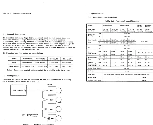
1.1 General Description
M244X series streaming Tape Drive is direct reel to reel servo type tape drive a_nd consist of tape transport mechanism, tape motion control
electronics, dual density read/write circuit and data formatter electronics which can read and write ANSI-standard nine track half inch magnetic tape in 6,250 BPI (GCR mode) or 1,600 BPI (PE mode). The M244X AC has a buffer adapter and the buffer adapter can elimenate the streamer restriction such as command reinstruct time reposition time.
M244X series has four modes as shown below.
Model M2441A/AC M2442A/AC M2443A/AC M2444A/AC
Form Standalone rack mount Standalone rack mount
Tape speed 12.5*/100 IPS 12. 5*/100 IPS 25*/75 IPS 25*/75 IPS
Note: Tape speed marked with asterisk is available only in A type.
1.2 Configuration
A maximum of four MTSs can be connected to the host controller with daisy chain connection as shown in Figure 1.1.
M244X
Host Controller FMT
FMT
FMT
FMT: Build-in formatter
T Line Terminator
1.3 Specifications
1.3.1 Functional specifications
Table 1.1 Functional specifications
Models M2441A/M2442A M2443A/M2444A M2441A/ M2443AC/
M2442AC M2444AC
Tape Speed 100 !PS 12.5 !PS 75 IPS 25 !PS 100 IPS 75 IPS
and Mode Streaming Start/Stop Streaming Streaming Streall\ing Streaming
Recording GCR 6250 BPI
Density
PE 1600 BPI
Data Transfer GCR 625 KB/sec 78 KB/sec 469 KB/sec 156 KB/sec
Rate 60 - 1000
PE 160 KB/sec 20 KB/sec 120 KB/sec 40 KB/sec
GCR 0.3 Inch
IBG
PE 0.6 Inch
Access GCR 166 ms 21 ms 126 ms SO ms
Time (Write) 0.2 - 5.0 (emulated)
PE 170 ms 25 ms 130 ms 63 ms
Repositioning GCR 792 ms
-
580 ms 176 ms 792 ms 580 ms TimePE 794 ms
-
582 ms 196 ms 794 ms 582 msCommand GCR 1.2 ms
-
1. 7 ms 5. 7 ms 1.2 ms 1. 7 msReinstruction
Time (Write) PE 4.2 ms
-
5. 7 ms 17. 7 ms 4.2 ms 5. 7 msRewind Time (2400FT) 136 sec
Load Time 10 sec
Tape Media 1/2 Inch Width Standard Tape for Computer 2400/1200/600/300 feet
Buffer size
-
256 lCB [image:10.802.59.698.40.560.2]1.3.2 Physical specifications 1.3.3 Reliability and maintenablity
Table 1.2 Physical specifications (1) Service life
Item Operating Not operating More than five years or 40,000 hours.
Voltage 100'Vl20V or 200"-240V ±10% (2) MTBF
Power Frequency 48"'61 Hz
requirement More than 8,000 hours.
Phase Single (3) MTTR
Power consumption Max 0.8 KVA 0.4 KVA at 100'Vl20V 0.5 KVA at 200"-240V l hour.
Heat dissipation Max 440 Kcal/Hour (1, 750 BTU/Hour)
Circuit breaker ·capacity 20A
Leakage current Less than l mA
Air flow 4 m3/min
Sound pressure level max 52 dB
Temperature S"'40°c (4l"-l04°F) 0"-50°c (32"-l22°F)
Relative humidity 20"'80% RH 8"-90% RH
Wet bulb 0"-29°c (32"'84 °F)
Environment Temperature change rate 15°C/Hour (27°F/Hour)
-'-RH change rate 30%/24 Hours
Altitude -609'V3,048 m (-2,000"-10,000 ft)
Vibration max 0.25G max 0.4G
Dimensions M2441A/M2443A 1,000 DUD X 500 DUD X 700 DDD
(Height x (39.4 inch x 19.7 inch x 27.6 inch)
width x 575
DDD X 482 DDD X 580 DDD
Depth) M2442A/M2444A (22.6 inch x 19.0 inch x 22.8 inch)
M2441A/M2443A 110 kg (242 lb)
Weight
M2442A/M2444A 90 kg (198 lb)
Service clearances Front: 1 m, Rear: l m Side : Not required
[image:11.798.85.551.58.518.2]l.4 Recording Method
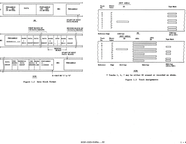
The Formatter provides the capability of recording and retreiving data in the
Phase Encoded (PE) format or the Group Coded Recording (GCR) format. Each
recording format is implemented in accordance with the ANSI standards. Track Assignments and Data Block Format are shown in Figures l.2 and 1.3.
1.4.1 Phase Encoding format
In the Phase Encording (PE) format each bit is recorded on tape as flux transition at mod-cell-time. A "O" is represented by a transition away from
the erase direction; a "l" by a transition made, i f necessary, at the
cell-boundary-time in order to allow the correct transition direction at the subsequent mid-cell-time.
Each track is therefore self-clocking, thus allowing a certain amount of skew between the bits of a byte. Deskewing is performed during read data
recovery. Data errors caused by failure of a single track are corrected on the fly during read operations.
A block of data consists of a preamble, the data and a postamble. The preamble consists of 40 bytes of all "O's" followed by a byte of all "l's", while the postamble consists of a byte of all "l's" followed by 40 bytes of all "O's". The preamble and postamble are mirror image of each other, allowing the block to be read in reverse.
A t~pe mark is special conbination of 64 to 256 flux transitions at 3200 FRPI in Tracks 1, 2, 4, 5, 7 and 8, and DC erasure in Tracks 3, 6 and 9.
When writing starts at BOT, the PE ID burst is written in the BOT area followed by a gap before the first data block. The ID burst is a single active track (Track 4) at 1600 RPI with the rest of the tracks DC erased.
1.4.2 Group Coded Recording format
In the Group Coded Recording format (GCR), the NRZI recording technique is used; i.e., each "l" recorded on tape is represented by a flux change and "O"
is represented by no flux change. In order that each track may be
self-clocking and thereby tolerate a considerable amount of skew, the write data is remapped such that 4 bytes of write data is transformed to 5 bytes of data written on the tape. This transformation is performed in such a way as to guarantee that no more than 2 consecutive "O's" will occur without an intervening "l". The user data is broken up into groups of 7 bytes. An 8th byte, the Error Correction Character (ECC) is calculated and added to the
group. The data group of 8 bytes is devided into two subgroups of 4 bytes.
Each subgroup of 4 bytes is transformed from a 6-bytes subgroup of data written on tape in the manners at Table 1.3.
A block of data consists of a preamble, a Mark I subgroup, up to 158 data groups, an end mark subgroup, a residual group, a CRC go up, a Mark II subgroup, and a postamble. As in PE, the Mark II subgroup and the postamble
are mirror images of the preamble and Mark I subgroup. The preamble consists
of a beginning subgroup of a alternate "l's" and "O's",. a second subgroup of one "O" and 4 "l's" followed by 14 subgroups of sync bytes, all "l's". If the user data creates more than 158 data groups a resync burst consisting of a Mark II, 2 sync subgroups and a Mark I is inserted every 158 data groups. The first 6 bytes of the residual group consists of the remainder of the
write data bytes plus any required pad of data "O's". The 7th byte is an
auxiliary CRC byte and the 8th byte is the ECC. The group is recorded in the
same manner as a data group after 4 to 5 bit transformations.
The first byte of the CRC group is a data "O" if the number of groups is even or the CRC character if the number of preceding
odd. The 2nd through 6th byte is the repeated CRC character.
is a residual character which is related to the number of data
8th byte is the ECC. The group is recorded in the same manner
group. Data errors caused by one or two track failures can be
the fly.
preceding data data groups is The 7th byte bytes. The as a data
corrected on
In PE, the tape mark and ID burst at BOT are unique combinations of active
and inactive tracks. The tape mark is the special combination of 250 to 400
flux transitions at 9042 FRPI in Tracks 1, 2, 4, 5 and 8, and DC erasure in
Tracks 3, 6 and 9. The ID is a burst at 3014 FRPI in Track 6 only; the rest
of the tracks are DC erased.
GCR has a GCR ID and an ARA (Automatic Read Amplification) burst followed by
an ARA ID before the first data block. the ARA burst is used to
automatically set the gain of the Read Amplifiers in each track to the optimum value for best reading. The ARA is recorded at 9042 FRPI in every track while the ARA is recorded at 9042 FRPI in Tracks 2, 3, 5, 6, 8 and 9 and DC erased in Tracks 1, 4, and 7.
Table 1.3 4 to 5 Bit Transformation
Data Storage Data Storage
Subgroup Subgroup Subgroup Subgroup
0000 11001 1000 11010
0001 11011 1001 01001
0010 10010 1010 01010
0011 10011 1011 01011
0100 11101 1100 llLlO
0101 10101 1101 01101
0110 10110 1110 01110
PREAMBLE !BG (41 BYTES) 00 ... 001
PREAMBLE
DATA POST AMBLE 100 ... 000
MARK
(41 BYTES)
FIRST BLOCK OF 158 DATA GROUPS
~
'L
DATA DATA DATA MARK IBG
slc
MARKPREAMBLE
START OF NEXT DATA BLOCK
SECOND BLOCK OF 158 DATA GROUPS
~
DATA
c
BG1010101111. . .111 I II
., I···
I!GROUP pROUP
J
DATA END~GROUP
MARK11111
00111 GROUP
RESIDUAL CRC MARK DATA DATA II GROUP paou~ 11100
GCR
11100 00111 GROUP
I RESYNC_j
1-- BURST
START OF NEXT DATA BLOCK
J_
POST AMBLE
11.. !BG PREAMBLE
111101010 x
T
X =MAY BE "l"or "O"
Figure 1.2 Data Block Format
(BOT AREA)
Track Binary ID Tape Mark
No. Value
9 2' c:::==:::i
8 2'
7 2' c=:=:::J
6 2'
5 2'
4 p
3 2' c=:=:::J
2 2'
I 2'
Reference Edge 1600 frpl PE 3200 frpi
64to 250 I (BOT AREA)
Track Binary ID ARA ARA
No. Value ID Tape Mark
9 2'
8 2'
7 2' c:::::::J
6 2'
5 2' c:::::J
4 p
c:::J
3 2'
2 2'
I 2' c:::J
c:::J
Reference Edge 3014 frpi 9042 frpi 9042 frpi
250 to 400 t
*Tracks 1, 4, may be either DC erased or recorded as shown.
Figure 1.3 Track Assignments
[image:13.799.72.718.47.547.2]CHAPTER 2 INSTALLATION
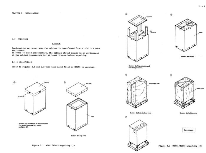
2. 1 Unpacking
CAUTION
Condensation may occur when the cabinet is transferred from a cold to a warm environment.
In order to avoid condensation, the cabinet should remsin in an environment at the ambient temperature for at least 3 hours before unpacking.
2.1.1 M2441/M2443
Refer to Figures 2.1 and 2.2 when tape model M2441 or M2443 is unpacked.
Lock knob
Remove four lock knobs on Top cover side. For detaied removing lock knobs, see figure 2.4.
Remove the Top cover
Sleeve
®
Remove the Top protector and four Side protectors.
Polyethy~ne cover
Remove the Polyethylene cover
©
®
Remove the Sleeve
Bubbleco'ler
llemCJ\!e the bubble cover
[image:14.801.31.731.45.564.2]2.1.2 M2442/M2444
Refer to Figures 2.3 and 2.4 when tape model M2442 or M2444 is unpacked.
(i)
Remove six Lock knobs on each side of the Outer cover. For detailed removing Lock knobs, see Figure 2.4.
Polyethylene cover
Remove the Polyethylene cover.
©
Remove the Outer cover.
Remove the Bubble cover.
Figure 2.3 M2442/M2444 unpacking
BOJP-5325-0lOOA ••• 02
©
Remove the Inner cover. Remove AC power cable from top of unit.
®
The Look knob moving method is as follows:
1. Nip the two limbs and release latches (CD) •
2. Pull down the limb part (@).
3. Remove the knob from each side of outer cover
C(])).
2.2 Mechanical Installation
2.2.1 M2441/M2443 installation
This section is applied to the standalone type tape drive.
(1) Front cover/rear cover opening
The opening method of the front cover and the rear cover is the same.
First, open the top cover adequately. Then release the two latches by pushing down the each plate of latches through the hole using a screw-driver.
Figure 2.5 shows the front cover opening. Figure 2.6 shows the rear cover opening.
After releasing the cover, disconnect the frame grounding wire from it by
removing the screw. See Figure 2.7.
(2) Front cover/rear cover closing
Connect the frame grounding wire to the cover with the screw. Next fit
the cover to the latches by pushing in on it.
(3) Adjustment of the leaving feet
To secure the M2441 or M2443 streaming tape unit, adjustment of the level feet is necessary.
Place the pads under the leveling feet and adjust the level by using a wrench. Adjust four leveling feet.
Figure 2.5 Top cover opening
Rear Cover
Figure 2.6 Rear cover opening
Frame Grounding Wire
Screw
Figure 2.7 FG wire removing
To raise a foot To lower a foot
Pad
2.2.2 M2442/M2444 installation
(1) Outside view
<
l
Figure 2.9 shows the outside view of the drive and Figure 2.10 shows the outside view of the rack.
482 580
Front door
Mounting rail
658
Figure 2.9 Outside view of the drive (rack mount type)
465 12
;
1
Q450 min.
(2) Mounting Method
a. The method of removing the pair mounting rails attached to the unit.
Note: The Right Rail is shown in Figure 2.9 right side view. Each rail is fixed to the unit by two screws. The screws are located on the front and rear sl.des.
{a) Open the front door.
(b) Loosen the two screws A indicated in Figure 2.11 and open the casting panel.
Caution; The center of gravity moves to the front when the panel is opened. Care should be taken so the drive does not tip forward.
(c) Remove the philips type screw B indicated in Figure 2.11. Remove the left side screw in the same manner.
(d) Remove the philips type screw C indicated in Figure 2.12. Remove the left side screw in the same manner.
(e) Close the casting panel and fix the screw A, and close the front door to prevent the door from opening unexpectedly when sliding the unit on the rails.
A
@o
Magnetic tape panel@1
A
A
Figure 2.11 Mounting rails removal (1) Figure 2.12 Mounting rails removal (2)
B03P-5325-0100A .•• 02
Figure 2.13 Mounting rails removal (3)
b. The method of mounting the rails to the rack
(a) Remove all the A screws. (Refer to Figure 2.14)
(b) Adjust the rails to the rack. (Refer to Figure 2.17)
As As
D=25": refer to Figure 2.14
D=28" or 30": reassemble the rails indicated Figure 2.15 (for 28") or Figure 2.16 (for 30").
Fix the screw B temporarily.
(c) Fix the rail to the rack using each 3 holes, one of which is
the lowest hole of the 12th pitch and the rest are the top and next hole of the 13th pitch, i.e. the highest of these 3 holes is 520.7 mm from the top hole of the rack. (Refer to Figure 2. 17)
(d) Fix the screws B which are fixed temporarily.
Tf
! If . I I ,I
'f
I
Figure 2.15 Rail mounting (2)
Figure 2.16 Rail mounting (3)
0
: } 1st pitch
;, } 12th pitch
®'
®:}
~j
13th pitchc. Mount the unit on the rail from front side
d. The method of the fixing the unit to the rail
Fix the screws in the reverse sequence as the method of removing. (Refer to Section 3.1)
Caution: Ff.x the back side screws for the first time.
Never open the casting panel before fixing the back side screws to prevent the unit ·falling down front side because of unbalance.
e. Fix the screws indicated in Figure 2.11.
(3) The method of removing
Carry out in the reverse sequence of mounting.
CABLE·A
CABLE·B
Back view
2.3 Cable Connection
2.3.l Interface cable and power cable
AC POWER CABLE
Confirm that the Interface cable A and B and AC power cable indicated in Figure 2.18.
r---,
I I
I I
I I
L _____
JG
Connector
(CNIS)
Figure 2.18 Cable connection
2.4 Checkout
Note: The location and the nickname of PCA is shown in Appendix.
Please refer to the Appendix if necessary.
2.4.l Input voltage setting
Note: This machine was set to 100~120 VAC.
(1) a. Confirm that the connector (CN15) indicated in Figure 2.19 is
plugged into the upper side of the power supply unit.
b. In case of 200~240 VAC
Confirm that the connector (CN15) indicated in Figure 2.19 plugs into the upper side of the power supply unit.
(2) Input voltage changing method
a. Remove the connector (CN15).
b. Remove the two screws.
c. Reverse the plastic cover.
d. Confirm that the label on to the plastic cover indicates correct voltage.
e. Fix the plastic cover by two screws.
f. Plug the connector in to the jack.
r----,
' '
' '
' '
Back view
•----'~
Figure 2.19 Input voltage setting
Connector
(CNIS)
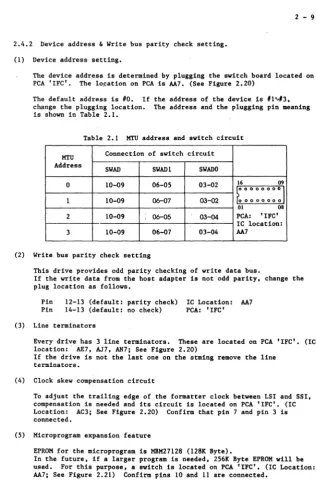
2.4.2 Device address & Write bus parity check setting.
(1) Device address setting.
The device addr_ess is determined by plugging the switch board located on
PCA 'IFC'. The lo~ation on PCA is AA7. (See Figure 2.20)
The default address is #0. If the address of the device is #1~#3,
change the plugging location. The address and the plugging pin meaning is shown in Table 2.1.
Table 2.1 MTU address and switch circuit
MTU Connection of switch circuit
Address
SWAD SWADl SW ADO
0 10-09 06-05 03-02 16 09
~oooooooJ
l 10-09 06-07 03-02 0 0 0 0 0 0 0 0
01 08
2 10-09 06-05 03-04 PCA: 'IFC'
IC location:
3 10-09 06-07 03-04 AA7
(2) Write bus parity check setting
(3)
This drive provides odd parity checking of write data bus.
I f the write data from the host adapter is not odd parity, change the plug location as follows.
Pin 12-13 (default: parity check)
Pin 14-13 (default: no check)
Line terminators
IC Location: AA7 PCA: 'IFC'
Every drive has 3 line terminators. These are located on PCA 'IFC'. (IC location: AE7, AJ7, AN7; See Figure 2.20)
If the drive is not the last one on the stming remove the line terminators.
(4) Clock skew compensation circuit
To adjust the trailing edge of the formatter clock between LSI and SSI,
compensation is needed and its circuit is located on PCA 1IFC'. (IC
Location: AC3; See Figure 2.20) Confirm that pin 7 and pin 3 is connected.
(5) Microprogram expansion feature
EPROM for the microprogram is MBM27128 (128K Byte).
In the future, i f a larger program is needed, 256K Byte EPROM will be
[image:22.796.410.728.48.538.2].--•--, r - - ' - - i
.--•--.
.--.--.
.-.--,.--.----.
,--,__,
.--•--..--•--, .--•--.
,--.--,r-'--i ,.--.-.... .--•---,
""
....
r
'C
[. L" r3'
i
'[
r
3[
'E
't
r' "" I.
..
.~ rL j
[.
1
LL
{
1
r1
't
f
f
3'
J; '
-,
r
f
.... ,
L
r
f
3-
r3-f
I,
'!'.
, ... 1
J;;,
{
1
{
L-:r
1
J;
L ' J;
... J
f
f
Lf
J;
L
f
3-[. L
'
{'
-1
i
I1
r
!
L'\'.I
f.
-!
i
3'
f
3-{
3,
{
1
f
1
t
3'
J;
1
L
f
1
' - - • - - '
.__,__.
'--•----'.___,____.
Notes:
!.
1. Clock skew compensation for formatter
2. Address setting & write bus parity check setting Notes:
3. Three line terminators 1. Microprogram expansion feature
Figure 2.20 Overview of PCA 'IFC' Figure 2.21 Overview of PCA 'MPU'
2.4.3 Setting by Operator Panel
The interface of M244X is the standard Pertee interface. The M244X has three variations of Pertee. (See, Sections 4.2 and 4.3). The default of the
interface mode is Mode A. If a change to another mode is needed, the setting
can be changed by the Operator Panel.
The density select mode is changable by the Operator Panel. (See, Section
3.2). The default of the density after the power up sequence is 6250 bpi &
Host Select mode. But it is selectable to other mode (i.e. 1600 bpi & not
Host) by the Operator Panel.
The !BG Length Mode is also selectable. The default value of the IB is normal length, but if the variable !BG length mode is set, the !BG length will be expanded up to twice of normal !BG.
The method of these three functions is described in chapter 6, REP 2320.
2.5 Diagnostics
For checking out the unit after the installation, the M244X has powerful
offline diagnostics. These routines can be executed easily by the operator
panel. The details are described in Appendix B.
Routine 01 should be executed for the purpose of complete check out. During
diagnostics, the routine ID is displayed in the 7 segment LEDs. At the end
of the diagnostics, 'OO' is displayed. But if some error is encountered, the Fault Symptom Code (FSC) is displayed in 7 segment LEDs and the Fault
Location code (FLC) is displayed by an operation of the panel. (See Section
3.2 and Appendix B)
The detail description of Fault Symptom Code is explained in chapter 5.
During diagnostics, no retry will be executed. So the error as FSC E2xx,
E3xx, DOlO or Dl80 may be encountered because of not good tape media. In
CHAPTER 3 OPERATION
3.l Power ON/OFF switch
The power switch shown on the right side of Figure 3.l is for the main AC line of the unit.
Power is supplied as "l" (upperside) is pushed, and cut off as "O" (lower side) is pushed.
When the power switch is turned on, all indicators of the operator panel are illumin·ated for one second during the indicator malfunction test. Power on diagnostics are automatically executed after all DC lines stable, then the 2-Digit indicator indicates normal code "OO". If the firmware detects an error, it indicates a Fault Symptom Code in the 7 segment L.E.D .•
0
I ''I
0
L/
Cl,
File~--~--~ Protect Density Select oHost
06250
01600
Figure 3.l Operator Panel
3.2 Operator Panel
Figure 3.1 shows the operator panel which can be used in either normal operation or diagnostic mode. The key and indicator function for diagnostics are described in Appendix B.
3.2.1 Start key and indicator
When tension is not applied to the tape (Servo off State), this switch initiates the load sequence. After the load sequence is completed, the unit becomes ready. Tbe load sequence has two different sequences depending if tape has already advanced beyond BOT or not.
(1) If this key is pressed after the tape is mounted and wound on the machine reel, the tape is tensioned and moved forward to the BOT.
(2) If this key pressed when the tape has already advanced beyond the BOT, the tape is tensioned and moves forward for 64 revolutions then rewinds BOT at high speed.
(3) This key is effective only when the Start Indication is not illuminated.
(4) This indication is illuminated when the unit is ready and enabled to the controller.
(5) If the Reset key is pressed, this indication turns off. Pressing the Start Key, the unit becomes ready again after the completion of rewinding to BOT.
3.2.2 Unload key and indicator.
(1) This key is effective only when the unit is in not ready state. (Start indication is OFF.)
(2) Pressing this key rewinds the whole tape on ·to the supply reel.
(3) This indicator is lit during unload operation.
3.2.3 Test key and indicator
This key is used for diagnostics.
Refer Appendix B for details.
3.2.4 Reset key
(1) Pressing this key puts the unit in the offline mode (not ready state) and reset test mode if you are in diagnostics,
3.2.5 Density Select key
This key selects the write density mode (HOST/6250/1600) of the unit.
Pressing this key changes the write density mode in a cyclic way shown as follows.
[HOST - - - 6250 - - - 1600
J
This key is ignored when the unit is online or in the diagnostic mode.
The density for reading depends on the written tape (6250 or 1600). the reading of tape does not cause any change of density mode indicator.
3.2.6 File protect indicator
(1) The indicator is illuminated when the Write Enable Ring is not mounted on the file reel.
(2) A write operation is inhibited if this indicator is illuminated.
3.2.8 2-Digit indicator
This indicator indicates the power-ON state or the details of unit errors.
(1) Normal Power ON State
"OO" code is indicated.
(2) Error State l (Load Check Code)
When a load failure occurs the two digit indicator on the operator panel blinks the load check code.
The code and meanings are:
Ll: Door opened L2: Reel latch opened
L3: Tape loosened
L4: BOT marker not found LS: Tape not in tape path
(3) Error State 2 (Fault Symptom Code)
3.2.7 Density indicators (HOST/6250/1600) When a hardware failure occurs the two digit indicator on the operator
panel displays two bytes of FSC (Fault Symptom Code). The FSC shows the
These LEDs indicate the density mode while writing the data to tape. cause of the error and the index is in the maintenance section.
The LEDs do not indicate the reading density.
( 1) HOST
This I.ED indicates that the unit can change the write density by Host
command.
(2) 6250
This LED indicates that the write density mode of the unit is set to 6250 (GCR). When this LED is lit, the density change command from the Host is ignored.
(3) 1600
This LED indicates that the write density mode of the unit is set to 1600 (PE). When this LED is lit, the density change command from the Host is ignored.
1-
-
,1
-_ / • L
/7
!/
LI.
I I
(a) Upper byte (b) Lower byte
The above indications are changed for one second cyclically.
Figure 3.2 FSC Indication
(4) Diagnostic routines and error codes
When the unit is in Test (diagnostic) mode, these indicators display their test routine ID number and the results of test.
Refer to Appendix B for further details.
CHAPTER 4 THEORY OF OPERATION
4.1 Mechanism
4.1.l Tape drive mechanism
Figure 4.1 shows an outline.
All parts that form the tape path, such as reel hub, head unit, and machine
reel, are mounted on the tape deck.
Tape passes over the tension sensor and the tape guides, and is then wound on
the machine reel via an idler.
The reel hub and machine reel are connected directly to a DC motors with a built-in tachometer.
A tension sensor detects the tape tension, and the idler sensor detects the tape speed and position by means of built-in tachometers.
An write enable sensor is attached close to the reel hub to detect whether a write enable ring is on the tape. This sensor also detects whether the reel is locked.
The head unit contains a tape cleaner, erase head, read/write head, and read/write circuit. A tape guide is attached on both sides of the head unit, and a shield block is installed facing the head.
A sheet-type operation panel is installed on the front door; it contains push buttons, LEDs, and an on/off switch.
Tension Roller
Reel Hub
Machine Reel Shield Block
Guide
Idler Roller/Sensor
( 1) Reel hub
The reel hub is operated manually. When the knob is pushed by hand, the cam is pulled to the reel boss by a link mechanisl!l. Then a claw is pushed out to expand the rubber, and locks the reel in place. When the cam is pulled, the reel lock detection ring moves inside, which moves the shield (that covered the sensor) so that light passes through. This enables the mechanisl!l to recognize that the reel has been locked.
(2) Enable sensor and reel lock sensor
As shown in the figure, there are spaces for two types of shields:
(3) Tension sensor
A roller bearing is attached to an arm and acoil spring is attached to the arm. Changes in tape tension result in a change in the angle of arm. A tachometer disk with a slit is connected to the center shaft, changes in the arm angle will cause a change from the initial location. A dumpening mass on the shaft protects the arm from resonance that may be caused when start/stop operations are repeated in certain regular
intervals.
(4) Idler tachometer
A shield for enable sense and shield for reel lock sense. These shields A tachometer disk is attached to the other side of the roller guide
are round springs, which return to the original position by means of detects the tape speed.
elasticity.
The shields for sensor function as shown in the following table:
Reel lock
Locked Not locked
Attached A
x
Write enable ring
Not attached 0
x
x:
No sensor outputA: Sensor output repeats ON and OFF by file reel rotation.
o: Sensor output is always on.
The sensor operates in the following sequence:
Write~nable
ring attached y
Tum the reel
motor a· lit tie
Reel unlocked
Reel motor stop
Error