Efficient Complexity Reduction Technique for Parallel
FIR Digital Filter based on Fast FIR Algorithm
J. Selvakumar
Assistant Professor, Department of ECE SRM University, Kattankulathur 603203,
Tamilnadu, India.
Vidhyacharan Bhaskar
Professor, Department of ECE SRM University, Kattankulathur 603203,Tamilnadu, India.
ABSTRACT
The objective of the paper is to reduce the hardware complexity of higher order FIR filter with symmetric coefficients. The aim is to design efficient Fast Finite-Impulse Response (FIR) Algorithms (FFAs) for parallel FIR filter structure with the constraint that the filter tap must be a multiple of 2. In our work we have briefly discussed for L = 4 parallel implementation. The parallel FIR filter structure based on proposed FFA technique has been implemented based on carry save and ripple carry adder for further optimization. The reduction in silicon area complexity is achieved by eliminating the bulky multiplier with an adder namely ripple carry and carry save adder. For example, for a 6-parallel 1024-tap filter, the proposed structure saves 14 multipliers at the expense of 10 adders, whereas for a six-parallel 512-tap filter, the proposed structure saves 108 multipliers at the expense of 10 adders. Overall, the proposed parallel FIR structures can lead to significant hardware savings for symmetric coefficients from the existing FFA parallel FIR filter, especially when the length of the filter is very large.
Keywords
Symmetric Filter; Polyphase decomposed Fast Finite Impulse Response (FIR) Algorithm (FFA); Parallel FIR symmetric convolution; Very Large Scale Integration (VLSI); FFA technique.
1. Introduction
The significant area of research in VLSI System Design is the area-efficient high-speed data path logic systems. Digital Filters are one of the most widely used fundamental devices in DSP systems, ranging from multimedia signal processing to wireless mobile communications. FIR filters are used in high frequency applications, such as multimedia signal processing, whereas some other applications require high throughput with a low-power circuit such as Multiple Input Multiple Output (MIMO) systems used in cellular wireless communications. The transition bandwidth of the filter decides the order of the filter. As the bandwidth of the filter decreases, the order of the FIR filter increases. The order of the filter increases when narrow band transitions are required at the filter output.
A higher order digital filter is used in video ghost canceller for broadcast television, which reduces the effect of multipath signal echoes. Hence, an optimized parallel Fast Finite Algorithm that retains hardware complexity is required, if the order of the filter increases enormously. In the proposed FFA algorithm, power consumption is reduced by applying pipelining and parallel processing concepts used in VLSI DSP applications. The critical path reduction is obtained by pipelining mechanism that aims at reducing the critical path by interleaving pipelining latches along the system latency, whereas parallel processing is a powerful technique because it
can be used to increase the throughput of a FIR filter or reduce the power consumption of a FIR filter. Parallel processing increases the sampling rate by replicating hardware so that multiple inputs can be processed in parallel, and multiple outputs are generated simultaneously. As the parallel filter block size L increases, hardware complexity as well as cost also increases, which limits its practical implementation. Previous work aims at reducing hardware complexity of the parallel FIR Filter [1]-[7]. The Proposed FFA structure successfully overcomes the constraint that the hardware implementation cost of a parallel FIR filter has a linear increase with block size L. Fast FIR algorithms (FFAs) introduced [1]-[4] use approximately (2L-1) sub-filter blocks to implement a L-parallel filter, each sub-filter has length N/L. Area complexity is optimized by reducing bulky multipliers from (2N - N/L) to L x N using the FFA technique.
The Iterated Short Convolution (ISC) based linear convolution structure is transposed to obtain a new hardware efficient FFA filter structure which saves a large amount of hardware cost, especially when the length of the FIR filter is large [7]. Small-sized filtering structures are constructed [6]-[10] based on fast linear convolution, and then long convolution is decomposed into several short convolutions, i.e., larger block-sized filtering structures can be constructed through iterations of the small-sized filtering structures.
However, in both categories, symmetry of coefficients in the filter design has not been taken into consideration for the design of structures yet. This can lead to significant savings in hardware complexity and cost. In this paper, we provide a new parallel FIR filter structure based on FFA consisting of advantageous polyphase decompositions, which can reduce amounts of bulky multiplications in the sub-filter section by exploiting the inherent nature of the symmetric coefficients compared to the existing FFA fast parallel FIR filter structure.
This paper is organized as follows. A brief introduction of existing FFAs is shown in Section II. In Section III, the proposed parallel FIR filter structures are presented. Section IV investigates the complexity and comparisons. In Section V, the description of hardware implementation and the experimental results are shown. Finally, section VI presents the conclusions.
2. Fast FIR Algorithm (FFA)
In general the output of an n-tap FIR filter which can be expressed as in (1)
,
1
,
0
n
,
)
i
n
(
x
)
i
(
h
)
n
(
y
1 N
0 i
L-parallel FIR filter can be derived using polyphase decomposition as [3]
z
z
,
H
z
z
x
z
z
Y
.,
e
.
i
),
z
(
H
)
z
(
X
)
z
(
Y
1 L
0 r
r L r 1 L
0 q
q L Q 1
l 0 p
p L p
where
0 k
k p
1 L N
0 k
k r
0 k
k q
,
p
Lk
x
z
Y
,
r
Lk
x
z
H
,
q
Lk
x
z
x
for p, q, r =
0
,
1
,
,
L
1
[11].A. Existing 2 x 2 FFA Technique (L = 2 parallel) From (2), a two-parallel filter can be mathematically expressed as [1]-[3]
H
X
X
H
z
H
X
,
z
X
H
X
z
X
H
z
H
Y
z
Y
1 0 2 1 0 1 0 1 0 0
1 1 0 1 1 0 1 1 0
(3)
implying the sub-filter output as
.
X
H
X
H
Y
,
X
H
z
X
H
Y
0 1 1 0 1
1 0 2 0 0 0
(4)
Equation (3) and (4) shows the traditional two-parallel filter structure, which will require four length-N/2 FIR sub filter blocks, two post processing adders, and totally 2N multipliers and (
2
N
2
) adders. However, (4) can be written as
H
H
X
X
H
X
H
X
.
Y
,
X
H
z
X
H
Y
1 1 0 0 1 0 1 0 1
1 0 2 0 0 0
(5)
The implementation of (5) will require three FIR sub-filter blocks of length N/2, one preprocessing and three post processing adders, and 3N/2 multipliers and 3(N21) + 4 adders, which reduces approximately one fourth over the traditional parallel filter hardware cost from (4). A two-parallel (L = 2) FIR filter implementation using FFA obtained from (5) is shown in Fig. 1.
The 2-parallel filter can also be written in matrix form as
.
X
P
H
Q
Y
2
2 2 2 2 (6) [image:2.595.315.560.83.390.2][image:2.595.54.256.88.357.2]
Fig. 1: Existing FFA for Two-parallel FIR filter implementation
Fig. 2: Three-parallel FIR filter implementation using Existing FFA
B. Existing 3 x 3 Fast FIR Algorithm (L = 3 parallel) With reference to the three-parallel FIR filter using FFA can be expressed as [2]
],
X
H
z
X
H
X
H
)
X
X
)(
H
H
[(
Y
],
X
H
)
X
X
)(
H
H
[(
z
X
H
z
X
H
Y
2 2 3 0 0
1 1 1 0 1 0 1
1 1 2 1 2 1 3
2 2 3 0 0 0
(7)
To utilize the symmetry of coefficients, the hardware implementation of (7) requires six length-N/3 FIR sub-filter blocks, three preprocessing and seven post processing adders, and three N multipliers and
2
N
4
adders, which has reduced approximately one third over the traditional three-parallel filter hardware cost. The implementation obtained from (7) is shown in Fig. 2.The 3-parallel filter can be expressed in matrix form as.
X
P
H
Q
Y
2
2 2 2 2 C. Conventional 4 x 4 Parallel FFA FIR Filter
)
H
z
H
)(
X
z
X
(
Y
)
H
z
H
z
H
z
H
(
)
X
z
X
z
X
z
X
(
Y
z
Y
z
Y
z
Y
Y
1 1 0 1 1 0 3 3 2 2 1 1 0 3 3 2 2 1 1 0 3 3 2 2 1 1 0
where.
,
,
,
2 2 1 1 2 2 0 0 3 2 1 1 2 2 0 0H
z
H
H
H
z
H
H
X
z
X
X
X
z
X
X
i.e., 2 2 4 2 2 0 0 2 0 2 0 2 0 0 0 2 0 0 2 0 0 0 1 1 2 1 1 0 0 1 0 1 0 1 0 0H
X
z
]
H
X
H
X
)
H
H
)(
X
X
[(
z
H
X
)
H
z
H
)(
X
z
X
(
H
X
H
X
z
]
X
H
X
H
)
H
H
)(
X
X
[(
z
H
X
Y
and ). H H )( X X ( z ) H H )( X X ( ) H H )( X X ( ) H H H H ( )] X X X X [( z ) H H )( X X ( ) H H ( z ) H H )][( X X ( z ) X X [( ) H H )( X X ( H X z ] H X H X ) H H )( X X [( z H X ) H z H )( X z X ( H X 3 2 3 2 4 3 2 3 2 1 0 1 0 3 2 1 0 3 2 1 0 2 1 0 1 0 3 2 2 1 0 3 2 2 1 0 1 0 1 0 3 3 4 3 3 1 1 3 1 3 1 2 1 1 3 2 1 3 2 1 1 1 (8)The hardware implementation in (8) requires eight length-N/4 FIR sub-filter blocks, three preprocessing and fifteen post processing adders, and 9N/4 multipliers and (9N / 4) + 9 adders, which reduces approximately the hardware complexity by 20 %. The hardware description of existing four FIR filter using FFA algorithm is in Fig. 3.
3. Proposed FFA structures for symmetric
convolutions
The main objective of the proposed structures is to earn as many sub-filter blocks as possible which contain symmetric coefficients so that half the number of multiplications in the single sub-filter block can be reused for the multiplications of whole taps, which is similar to the fact that a set of both odd and even symmetric coefficients would only require half the filter
length of multiplications in a single FIR filter. Therefore, for an N-tap L-parallel FIR filter the total amount of saved multipliers would be the number of sub-filter blocks that contain symmetric coefficients times half the number of multiplications in a single sub-filter block (N/2L). [11]
A. Proposed FFA for L=2 parallel FIR
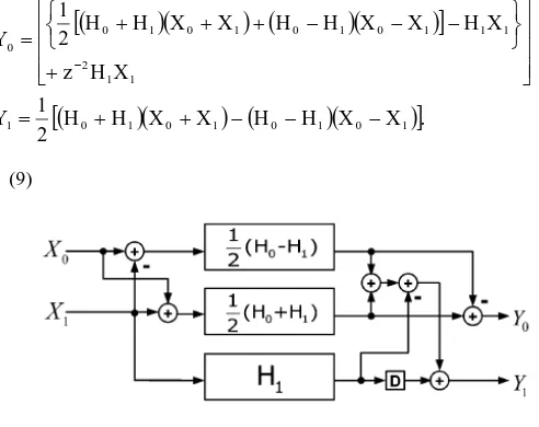
From (4), a two-parallel FIR filter can also be written as
[image:3.595.304.550.181.376.2]
(9)
Fig. 4: Proposed FIR filter for two-parallel implementation
When it comes to a set of even symmetric coefficients, (9) can earn
one more sub-filter block containing symmetric coefficients than (5), the existing FFA parallel FIR filter. Fig. 4 shows the implementation of the proposed two-parallel FIR filter based on (9). An example is demonstrated here for a clearer perspective.
Example: Consider a 1024-tap FIR filter with a set of symmetric coefficients applying to the proposed two-parallel FIR filter [11].
{h(0), h(1), h(2),h(3), h(4), h(5)….
h(6), h(7), h(8), h(9), …, h(39)} where h (39) = h(0), h(38) = h(1), h(37) = h(2), h(36) = h(20), h(4) = h(19), h(5) = h(18),….h(11) = h(12), applying to the proposed two-parallel FIR filter structure, and the top two sub-filter blocks will be given as
0 1
{ (0)
(1), (2)
(3),
H
H
h
h
h
h
(4) (5), (6) (7),...., (18) (19),
h h h h h h (20) (21), (22) (23)}
h h h h
where
(0) (1) ( (38) (39))
h h h h
(2) (3) ( (36) (37))
h h h h
(4) (5) ( (34) (35))
h h h h
(6) (7) ( (16) (17))...
h h h h
(10)
As observed from the above example, two of three sub-filter blocks from the proposed two-parallel FIR filter structures, H0-H1 and H0 + H1, are with symmetric coefficients,
now, as (9), which means the sub-filter block can be realized by Fig. 4, with only half the amount of multipliers required. Each
H H X X H H X X
.output of multipliers responds to two taps. Note that the transposed direct-form FIR filter is employed. Compared to the existing FFA two-parallel FIR filter structure, the proposed FFA structure leads to one more sub-filter block which contains symmetric coefficients. However, it comes with the price of the increase of amount of adders in preprocessing and post processing blocks. In this case, two additional adders are required for L = 2.
Existing FFA [11]
[image:4.595.94.204.183.421.2]
Proposed FFA
Fig. 6: Comparison of sub-filter blocks between existing FFA [11] and the proposed FFA four-parallel FIR
structures
B. 3 x 3 Proposed FIR structure using FFA (L=3)
With the similar approach, from (7), a three-parallel FIR filter can also be written as (12). Fig. 5 shows implementation of the proposed three-parallel FIR filter. When the number of symmetric coefficients N is the multiple of 3, the proposed three-parallel FIR filter structure presented in (12) enables four sub-filter blocks with symmetric coefficients in total, whereas the existing FFA parallel FIR filter structure has only two ones out of six sub-filter blocks. Therefore, for an N-tap three-parallel FIR filter, the proposed structure can save N/3 multipliers from the existing FFA structure. However, again, the proposed three-parallel FIR structures also bring an overhead of seven additional adders in preprocessing and post processing blocks.
1 1 1 0 1 0 1 0 1 0
2 0 2 0 2 1 0 2 1 0 3
1 1 1 0 1 0 1 0 1 0 0
X H ] X X H H X X H H [ 2 1
X X H H X X X H H H z
X H X X H H X X H H 2 1 Y
1 1 1 0 1 0 1 0 1 0
2 0 2 0 2 0 2 0 3
1 0 1 0 1 0 1 0 1
X H ] X X H H X X H H [ 2 1
X X H H X X H H 2 1
z
X X H H X X H H 2 1 Y
0 2 0 2 0 2 0 2 1 1
2
2
1
X
H
X
X
H
H
X
X
H
H
Y
(12)
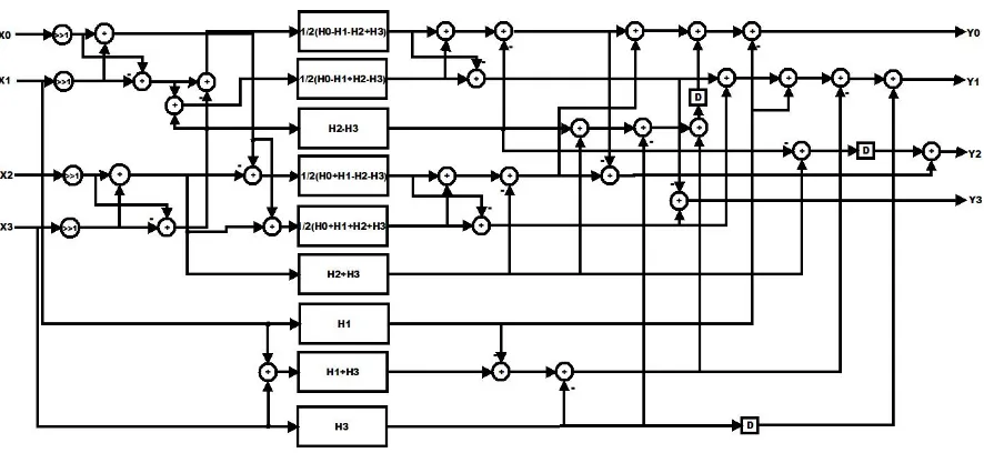
C. Proposed FFA Technique for Parallel FIR filter for Length (L = 4)
With the similar approach, from (9), a four-parallel FIR filter can also be written as (13). Fig. 7 shows implementation of the proposed four-parallel FIR filter. When the number of symmetric coefficients N is the multiple of 4, the proposed four-parallel FIR filter structure presented in (13) enables four sub-filter blocks with symmetric coefficients in total, whereas the existing FFA parallel FIR filter structure has only two ones out of six sub-filter blocks. A comparison figure is shown in Fig. 6, where the shadow blocks stand for the sub-filter blocks which contain symmetric coefficients. Therefore, for an N-tap four-parallel FIR filter, the proposed structure can save 3N/8 multipliers from the existing FFA structure. However, again, the proposed four-parallel FIR structures also bring an overhead of nine additional adders in preprocessing and 21 adder in post processing blocks.
' ' ' ' ' ' ' ' ' ' ' '
0 0
0.5
0
1 0
1
0
1 0
1
1 1X H
H
H
X
X
H
H
X
X
H X
2 2 2 2
0 2 1 3 0 2 1 3
2 2 2 2
0 2 1 3 0 2 1 3
2 2
1 3 1 3
1
2
.
Z Z Z Z
Z Z Z Z
H
H
H
H
X
X
X
X
H
H
H
H
X
X
X
X
H
Z H
X
Z X
(13)
4. Symmetric Convolutions Based Proposed
Cascaded FFA Structures
The proposed parallel FIR structure enables the reuse of multipliers in parts of the sub-filter blocks but it also brings more adder cost in preprocessing and post processing blocks. When cascading the proposed FFA parallel FIR structures for larger parallel block factor L the increase of adders can become larger.
Therefore, other than applying the proposed FFA FIR filter structure to all the decomposed sub-filter blocks, the existing FFA structures which have more compact operations in preprocessing and post processing blocks are employed for those sub-filter blocks that contain no symmetric coefficients, whereas the proposed FIR filter structures are still applied to the rest of sub-filter blocks with symmetric coefficients.
track of both the number of multipliers and the number of adders required for the filtering structure. The number of required multipliers is calculated as shown in equation (14).
1 1
,
r i r
i i i
N
M
M
L
(14)
where r is the number of FFAs used, Li is the block size of the FFA at step I, Mi is the number of filters that results from the
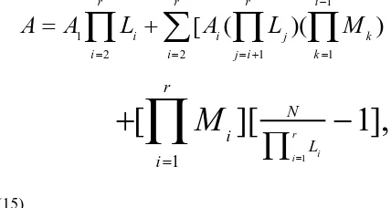
application of the ith FFA and N is the order of the filter. The number of required adders is calculated as
1
1
2
2 1 1
[
(
)(
)
r r r i
i i j k
i
i j i k
A
A
L
A
L
M
1 1
[
][
1],
ri i
r
N i
L i
M
(15)
where Aiis the number of pre/post-processing adders required
by the ith FFA. Consider the case of cascading two (2-by-2) FFAs. The resulting 4-parallel filtering structure would require a total of 9N/4 multipliers and 20 + 9 (N/4 -1) adders for implementation.
The reduced complexity 4-parallel filtering structure represents a hardware (area) savings of nearly 44 % when compared to 4N multipliers required in the traditional 4-parallel FIR filtering structure.
The proposed cascading process for four-parallel FIR filter (L = 4) and the realization is shown in Fig. 7. From Fig. 7, it is clear to see that the proposed four-parallel FIR structure earns three more sub-filter blocks containing symmetric coefficients than the existing FFA one, which means 3N / 8 multipliers can be saved for an N-tap FIR filter, at the price of 11 additional adders in preprocessing and post processing blocks. By this cascading approach, parallel FIR filter structures with larger block factor L can be realized. The proposed six-parallel FIR filter will result in 6 more symmetric sub-filter blocks, equivalently N/2 multipliers saved for an N-tap FIR filter, than the existing FFA, at the expense of an additional 32 adders. Also, the proposed eight-parallel FIR filter will lead to seven more symmetric sub-filter blocks, equivalently 7N/16 multipliers saved for an N-tap filter, than the existing FFA, with the overhead of additional 54 adders.
5. Hardware complexity Analysis and
comparison
When an L-parallel FIR filter comes with a set of symmetric coefficients of length N, the number of required multipliers for the proposed parallel FIR filter structures is provided by (16) and (17).
Case 1:
When
1
r i i
N
L
is even,1 1
(
)
2
r
i r
i i i
N
S
M
M
L
Case 2:
When
1
r i i
N
L
is odd,
1
1 1
(
(
)
1).
2
r
i
r r
i
i i
i i
N
S
N
M
M
L
L
(16)
Here, Li is the small parallel block size such as (2 x 2) or (3 x 3)
FFA. r is the number of FFAs used. Mi is the number of
sub-filter blocks resulted from ith FFA. S is the number of sub-filter blocks containing symmetric coefficients. The number of the required adders in sub-filter section is given as
1
1
(
1).
rsub i r
i
i i
N
A
M
L
(17)A comparison between the proposed and the existing FFA structures for even symmetric coefficients with different length under different level of parallelism is summarized in Table I. Also, a comparison between the proposed structures and other structures for a 144-tap FIR filter with parallel block 4 and 8 is shown in Table II.
Table I:
Comparison of proposed and existing FFA structures with number of required multipliers, reduced multiplier, number of required adders in sub-filter section, number of required adders in pre-processing and post-processing blocks
(i) For L = 2 Parallel FIR Filter:
Length 24-tap
36-tap
81-tap
512-tap
1024-tap Multipliers
Existing
FFA 36 54 122 768 1536 Proposed
FFA 30 45 102 640 1305 Reduced 6 9 20 128 231 Adders
(Pre/Post)
Existing
FFA 4 4 4 4 4 Proposed
FFA 6 6 6 6 6 Increased 2 2 2 2 2 Sub-Filters Block Adders 33 51 118 765 1533
(ii) For L = 3 Parallel Filter:
Length 24-tap
36-tap
81-tap
512-tap
1024-tap Multipliers
Existing
FFA 48 72 162 1024 2048 Proposed
FFA 40 60 135 854 1707 Reduced 8 12 27 170 341 Adders
(Pre/Post)
Existing
FFA 10 10 10 10 10 Proposed
[image:5.595.66.280.227.341.2](iii) For L = 4 Parallel FIR Filter:
Length 24-tap
36-tap
81-tap
512-tap
1024-tap
Multipliers
Existing
FFA 54 81 182 1152 2304 Proposed
FFA 44 66 149 940 1880 Reduced 10 15 33 212 424
Adders (Pre/Post)
Existing
FFA 20 20 20 20 20 Proposed
FFA 31 31 31 31 31 Increased 11 11 11 11 11 Sub-Filters Block Adders 45 72 173 1143 2295
(iv) For L = 6 Parallel FIR Filter:
Length 24-tap
36-tap
81-tap
512-tap
1024-tap
Multipliers
Existing
FFA 72 108 243 1536 3072 Proposed
FFA 60 90 203 1286 2566 Reduced 12 18 40 253 506
Adders (Pre/Post)
Existing
FFA 42 42 42 42 42 Proposed
FFA 74 74 74 74 74 Increased 32 32 32 32 32 Sub-Filters Block Adders 54 90 225 1518 3054
6. FPGA Implementation Analysis
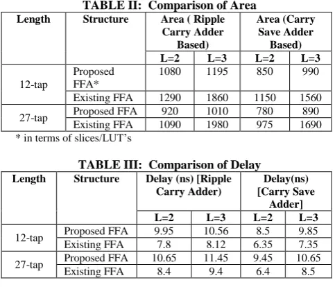
[image:6.595.52.290.89.224.2]The existing and proposed FFA structures are implemented in Verilog HDL targeted on Xilinx VirtexE FPGA device of filter length of 12 and 27, word length of 8-bit. The comparison results are tabulated as
TABLE II: Comparison of Area
Length Structure Area ( Ripple Carry Adder
Based)
Area (Carry Save Adder
Based) L=2 L=3 L=2 L=3 12-tap
Proposed FFA*
1080 1195 850 990 Existing FFA 1290 1860 1150 1560 27-tap Proposed FFA 920 1010 780 890
[image:6.595.53.290.93.352.2]Existing FFA 1090 1980 975 1690 * in terms of slices/LUT’s
TABLE III: Comparison of Delay
Length Structure Delay (ns) [Ripple Carry Adder)
Delay(ns) [Carry Save
Adder] L=2 L=3 L=2 L=3 12-tap Proposed FFA 9.95 10.56 8.5 9.85 Existing FFA 7.8 8.12 6.35 7.35 27-tap Proposed FFA 10.65 11.45 9.45 10.65
Existing FFA 8.4 9.4 6.4 8.5
7. Conclusions
The proposed efficient parallel FIR filter structures in this paper are advantages for symmetric convolutions or filter with symmetric coefficients. The Proposed parallel FFA technique is suitable for both even and odd number of tap which is a multiple of 2 or 3. Multiplier consumes the major area in the hardware for the parallel FIR implementation. The proposed structure extracts the nature of even symmetric coefficients and save a
significant multiplier area at the expense of additional adder in pre-processing and post processing adder block in FIR filter. The Proposed structures is implemented using ripple carry and carry save adder, where the carry save based FFA technique reduces the hardware complexity by approximately by 10%. Since an adder occupies less area when compared to multipliers, it is advantageous to exchange multipliers with adders in terms of hardware cost. Moreover the number of increased adders stays still the same when the length of FIR filter becomes large, whereas the number of reduced multipliers increases along with the length of the filter. The larger the length of FIR filters is, the more the proposed structure and save form the existing FFA structure. In this paper, we have proposed new parallel FIR structures for polyphase decompositions dealing with symmetric convolutions comparatively better than the existing FFA structure in terms of hardware consumption.
8. References
[1] D. A. Parker, and K. K. Parhi, “Low area/power parallel FIR Digital Filter implementations,” Journal of VLSI Signal Processing Systems, vol. 17, no. 1, pp. 75–92, Sep. 1997.
[2] Y. C. Tsao, and K. Choi, “Area-Efficient parallel FIR Digital Filter Structures for Symmetric Convolutions based on Fast FIR Algorithm,” IEEE Transactions on VLSI Systems, vol. 20, no. 2, pp. 366-370, Feb. 2012.
[3] J. G. Chung, and K. K. Parhi, “Frequency-spectrum-based low-area low-power parallel FIR Filter Design,” EURASIP Journal of Applied Signal Processing, vol. 2002, no. 9, pp. 444–453, Sep. 2002.
[4] K. K. Parhi, VLSI Digital Signal Processing Systems: Design and Implementation, NY: Wiley, 1999.
[5] Z. J. Mou, and P. Duhamel, “Short-length FIR filters and their use in fast non-recursive filtering,” IEEE Transactions on Signal Processing, vol. 39, no.6, pp. 1322–1332, June 1991.
[6] J. I. Acha, “Computational Structures for Fast Implementation of L-path and L-block digital filters,” IEEE Transactions on Circuit and Systems, vol. 36, no. 6, pp. 805–812, June 1989.
[7] C. Cheng, and K. K. Parhi, “Hardware Efficient Fast Parallel FIR Filter structures based on iterated short convolution,” IEEE Transactions on Circuits Systems I, Regular Papers, vol. 51, no. 8, pp. 1492–1500, Aug. 2004. [8] C. Cheng, and K. K. Parhi, “Further complexity reduction
of Parallel FIR filters,” Proceedings of IEEE International Symposium on Circuits and Systems (ISCAS 2005), Kobe, Japan, May 2005.
[9] C. Cheng and K. K. Parhi, “Low-cost Parallel FIR Structures with 2-stage parallelism,” IEEE Transactions on Circuits Systems I Regular Papers, vol. 54, no. 2, pp. 280– 290, Feb. 2007.
[10] I. S. Lin, and S. K. Mitra, “Overlapped Block Digital Filtering,” IEEE Transactions on Circuits & Systems II, Analog Digital Signal Processing, vol. 43, no. 8, pp. 586– 596, Aug. 1996.
[image:6.595.53.295.460.667.2]Fig. 3: Four Parallel Existing FFA Algorithms
Fig. 5: Proposed three-parallel FIR filter implementation
[image:7.595.55.498.534.738.2]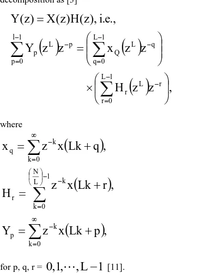
![Fig. 6: Comparison of sub-filter blocks between existing FFA [11] and the proposed FFA four-parallel FIR](https://thumb-us.123doks.com/thumbv2/123dok_us/8100713.787776/4.595.94.204.183.421/fig-comparison-filter-blocks-existing-ffa-proposed-parallel.webp)