Multi-Level
µTESLA: A Broadcast Authentication System for
Distributed Sensor Networks
∗Donggang Liu Peng Ning
Department of Computer Science North Carolina State University
Raleigh, NC 27695-7534
Emails: [email protected], [email protected]
Abstract
Broadcast authentication is a fundamental security service in distributed sensor networks. This pa-per presents the development of a scalable broadcast authentication scheme named multi-levelµTESLA
based onµTESLA, a broadcast authentication protocol whose scalability is limited by its unicast based initial parameter distribution. Multi-levelµTESLA satisfies several nice properties, including low over-head, tolerance of message loss, scalability to large networks, and resistance to replay attacks as well as denial of service attacks. This paper also presents the development of a multi-levelµTESLA broadcast authentication system on TinyOS, an operating system for networked sensors, and experimental results obtained through simulation.
1
Introduction
A distributed sensor network usually consists of one or several computationally powerful nodes called base
stations and a large amount of inexpensive, low capacity nodes called sensors (or sensor nodes). The nodes
in a distributed sensor network communicate through wireless communication, which is usually limited in bandwidth. Distributed sensor networks have extensive applications in military as well as civilian operations, in which it is necessary to deploy sensor nodes dynamically.
Broadcast authentication is an essential service in distributed sensor networks. Because of the large amount of sensor nodes and the broadcast nature of the communication in distributed sensor networks, it is usually desirable for the base stations to broadcast commands and data to the sensor nodes. In hostile environments (e.g., battle field, anti-terrorists operations), it is necessary to enable the sensor nodes to authenticate the broadcast messages received from the base station.
Broadcast authentication in distributed sensor networks turns out to be a non-trivial task. On the one hand, public key based digital signature mechanisms (e.g., RSA [19]), which are typically used for broadcast authentication in traditional networks, are too expensive to apply to sensor networks, due to the intensive computation involved in signature verification and the resource constraints on sensors. On the other hand, secret key based mechanisms (e.g., HMAC [11]) cannot be directly applied to broadcast authentication, since otherwise a compromised receiver can easily forge any message from the sender.
A protocol named µTESLA [17] has been proposed for broadcast authentication in distributed sensor networks, which is adapted from a stream authentication protocol called TESLA [15]. µTESLA employs a
∗A preliminary version of this paper has appeared in the Proceedings of the 10th ISOC Annual Network and Distributed Systems
chain of authentication keys linked to each other by a pseudo random function [9], which is by definition a one way function. Each key in the key chain is the image of the next key under the pseudo random function.
µTESLA achieves broadcast authentication through delayed disclosure of authentication keys in the key chain. The efficiency of µTESLA is based on the fact that only pseudo random function and secret key based cryptographic operations are needed to authenticate a broadcast message. (More details ofµTESLA can be found in Section 2.)
The original TESLA uses broadcast to distribute the initial parameters required for broadcast authenti-cation. The authenticity of these parameters are guaranteed by digital signature generated by the sender. However, due to the low bandwidth of a sensor network and the low computational resources at each sen-sor node, µTESLA cannot distribute these initial parameters using public key cryptography. Instead, the base station has to unicast the initial parameters to the sensor nodes individually. This feature severely limits the application ofµTESLA in large sensor networks. For example, The implementation ofµTESLA in [17] has 10 kbps at the physical layer and supports 30 bytes packets. To bootstrap 2000 nodes, the base station has to send or receive at least 4000 packets to distribute the initial parameters, which takes at least4000×30×8
10240 = 93.75seconds even if the channel utilization is perfect. Such a method certainly cannot scale up to very large sensor networks, which may have thousands of nodes.
In this paper, we propose an extension toµTESLA to address the above limitation. The basic idea is to
predetermine and broadcast the initial parameters required by µTESLA instead of unicast-based message transmission. In the simplest form, our extension distributes theµTESLA parameters during the initializa-tion of the sensor nodes (e.g., along with the master key shared between each sensor and the base stainitializa-tion). To provide more flexibility, especially to prolong the lifetime of µTESLA without requiring a very long key chain, we introduce a multi-level key chain scheme, in which the higher-level key chains are used to authenticate the commitments of lower-level ones. To further improve the survivability of the scheme against message loss and Denial of Service (DOS) attacks, we use redundant message transmissions and random selection strategies to deal with the messages that distribute key chain commitments. The resulting scheme, which is named multi-levelµTESLA, removes the requirement of unicast-based initial
communica-tion between base stacommunica-tion and sensor nodes while keeping the nice properties ofµTESLA (e.g., tolerance of message loss, resistance to replay attacks).
We have implemented multi-level µTESLA broadcast authentication system on TinyOS [10]. In this paper, we also describe the design and implementation of the multi-level µTESLA API as well as the ex-periments performed through simulation. Our exex-periments are intended to understand the performance of multi-levelµTESLA under severe attacks and poor channel quality. The experimental results demonstrate that our scheme can tolerate high channel loss rate and is resistant to known DOS attacks to a certain degree. The rest of this paper is organized as follows. The next section gives a brief overview of µTESLA. Section 3 presents the development of the multi-level µTESLA scheme. Section 4 describes the design and implementation of the multi-levelµTESLA API on TinyOS [10]. Section 5 presents our experiments performed through simulation. Section 6 discusses the related work, and section 7 concludes the paper and points out some future research directions. Appendix A presents the details of the two-levelµTESLA scheme, from which the multi-level µTESLA is extended. Finally, appendix B gives the details of the multi-levelµTESLA API.
2
An Overview of
µ
TESLA
high communication, computation and storage overhead of the asymmetric cryptographic mechanisms, it is impractical to implement them in resource constrained sensor networks.
µTESLA introduced asymmetry by delaying the disclosure of symmetric keys [17]. A sender broadcasts a message with a Message Authentication Code (MAC) generated with a secret keyK, which will be disclosed after a certain period of time. When a receiver receives this message, if it can ensure that the packet was sent before the key was disclosed, the receiver can buffer this packet and authenticate it when it receives the corresponding disclosed key. To continuously authenticate the broadcast packets,µTESLA divides the time period for broadcasting into multiple time intervals, assigning different keys to different time intervals. All packets broadcasted in a particular time interval are authenticated with the same key assigned to that time interval.
To authenticate the broadcast messages, a receiver first authenticates the disclosed keys. µTESLA uses a one-way key chain for this purpose. The sender selects a random valueKnas the last key in the key chain
and repeatedly performs a pseudo random function F to compute all the other keys: Ki =F(Ki+1),0 ≤
i ≤n−1, where the secret key Ki is assigned to theith time interval. With the pseudo random function
F, givenKj in the key chain, anybody can compute all the previous keysKi,0 ≤ i≤ j, but nobody can
compute any of the later keysKi, j+1≤i≤n. Thus, with the knowledge of the initial keyK0, the receiver
can authenticate any key in the key chain by merely performing pseudo random function operations. When a broadcast message is available inithtime interval, the sender generates MAC for this message with a key
derived fromKiand then broadcasts this message along with its MAC and discloses the keyKi−dassigned
to the time intervalIi−d, wheredis the disclosure lag of the authentication keys. The sender prefers a long
delay in order to make sure that all or most of the receivers can receive its broadcast messages. But, for the receiver, a long delay could result in high storage overhead to buffer the messages.
Each key in the key chain will be disclosed after some delay. As a result, the attacker can forge a broadcast packet by using the disclosed key. µTESLA uses a security condition to prevent a receiver from accepting any broadcast packet authenticated with a disclosed key. When a receiver receives an incoming broadcast packet in time intervalIi, it checks the security condition⌊(Tc+∆−T0)/Tint⌋< Ii+d, whereTcis the local
time when the packet is received,T0is the start time of the time interval0,Tintis the duration of each time
interval, and∆is the maximum clock difference between the sender and itself. If the security condition is satisfied, i.e., the sender has not disclosed the keyKi yet, the receiver accepts this packet. Otherwise,
the receiver simply drops it. When the receiver receives the disclosed key Ki, it can authenticate it with
a previously received key Kj by checking whether Kj = Fi−j(Ki), and then authenticate the buffered
packets that were sent during time intervalIi.
µTESLA is an extension to TESLA [15]. The only difference between TESLA andµTESLA is in their key commitment distribution schemes. TESLA uses asymmetric cryptography to bootstrap new receivers, which is impractical for current sensor networks due to its high computation and storage overhead.µTESLA depends on symmetric cryptography with the master key shared between the sender and each receiver to bootstrap the new receivers individually. In this scheme, the receiver first sends a request to the sender, and then the sender replies a packet containing the current time Tc (for time synchronization), a keyKi of one
way key chain used in a past intervali, the start timeTi of intervali, the durationTintof each time interval
and the disclosure lagd.
3
Multi-Level
µ
TESLA
The major barrier of usingµTESLA in large sensor networks lies in its difficulty to distribute the key chain commitments to a large number of sensor nodes. In other words, the method for bootstrapping new receivers inµTESLA does not scale to a large group of new receivers, though it is okay to bootstrap one or a few. The essential reason for this difficulty is the mismatch between the unicast-based distribution of key chain commitments and the authentication of broadcast messages.
In this section, we present our method to address the limitation ofµTESLA. The basic idea is to
prede-termine and broadcast the key chain commitments instead of unicast-based message transmissions. In the
following, we present a series of schemes; each later scheme improves over the previous one by address-ing some of its limitations except for scheme V. Scheme V improves over scheme IV only in special cases where the base station is very resourceful in terms of computational power and storage. The final one is the multi-levelµTESLA scheme, which has two variations based on schemes IV and V, respectively.
We assume each broadcast message is from the base station to the sensor nodes. Broadcast messages from a sensor node to the sensor network can be handled as suggested in [17]. That is, the sensor node unicasts the message to the base station, which then broadcasts the message to the other sensor nodes. The messages transmitted in a sensor network may reach the destination directly, or may have to be forwarded by some intermediate nodes; however, we do not distinguish between them in our schemes.
For the sake of presentation, we denote the key chain with commitmentK0ashK0ithroughout this paper.
3.1 Scheme I: Predetermined Key Chain Commitment
A simple solution to bypass the unicast-based distribution of key chain commitments is to predetermine the commitments, the starting times, and other parameters of key chains to the sensor nodes during the initialization of the sensor nodes, possibly along with the master keys shared between the sensor nodes and the base station. (Unlike the master keys, whose confidentiality and integrity are both important, only the integrity of the key chain commitments needs to be ensured.) As a result, all the sensor nodes have the key chain commitments and other necessary parameters once they are initialized, and are ready to useµTESLA as long as the starting time is passed.
This simple scheme can greatly reduce the overhead involved in distribution of key chain commitments in
µTESLA, since unicast-based message transmission is not required any more. However, this simple solution also introduces several problems.
First, a key chain in this scheme can only cover a fixed period of time. To cover a long period of time, we need either a long key chain, or a large interval to divide the time period. If a long key chain is used, the base station will have to precompute and store this key chain. In addition, the receivers will have to perform intensive computation of pseudo random functions if there is a long delay (which covers a large number of intervals) between broadcast messages. If a long interval is used, there will be a long delay before the authentication of a message after it is received, and it requires a larger buffer at each sensor node. Though the extensions to TESLA [16] can remove this delay and the buffer requirement at the sensor nodes, the messages will have to be buffered longer at the base station.
Second, it is difficult to predict the starting time of a key chain when the sensor nodes are initialized. If the starting time is set too early, the sensor nodes will have to perform a large number of pseudo random function operations in order to authenticate the first broadcast message. In addition, the key chain must be fairly long so that it does not run out before the sensor network’s lifetime ends. If the starting time is set too late, messages broadcasted before it cannot be authenticated viaµTESLA.
addi-tional techniques so that we not only avoid the problems of unicast-based distribution of key commitment, but also those of this simple scheme.
3.2 Scheme II: Naive Two-LevelµTESLA
The essential problem of scheme I lies in the fact that it is impossible to use both a short key chain and short time intervals to cover a long period of time. This conflict can be mitigated by using two levels of key chains.
The two-level key chains consist of a high-level key chain and multiple level key chains. The low-level key chains are intended for authenticating broadcast messages, while the high-low-level key chain is used to distribute and authenticate commitments of the low-level key chains. The high-level key chain uses a long enough interval to divide the time line so that it can cover the lifetime of a sensor network without having too many keys. The low-level key chains have short enough intervals so that the delay between the receipt of broadcast messages and the verification of the messages is tolerable.
The lifetime of a sensor network is divided inton(long) intervals of duration ∆0, denoted asI1,I2, ..., and In. The high-level key chain has n+ 1 elementsK0, K1, ...,Kn, which are generated by randomly
pickingKnand computingKi =F0(Ki+1)fori= 0,1, ..., n−1, whereF0is a pseudo random function. The key Ki is associated with each time interval Ii. We denote the starting time of Ii asTi. Thus, the
starting time of the high-level key chain isT1.
Since the duration of the high-level time intervals is usually very long compared to the network delay and clock discrepancies, we choose to disclose a high-level keyKiused forIiin the following time interval
Ii+1. Thus, we use the following security condition to check whether the base station has disclosed the key
Kiwhen a sensor node receives a message authenticated withKiat timet:t+δM ax < Ti+1, whereδM ax
is the maximum clock discrepancy between the base station and the sensor node.
Each time interval Ii is further divided into m (short) intervals of duration ∆1, denoted as Ii,1, Ii,2,
...,Ii,m. If needed, the base station generates a low-level key chain for each time interval Ii by randomly
pickingKi,mand computingKi,j =F1(Ki,j+1)forj= 0, ..., m−1, whereF1is a pseudo random function. The keyKi,j is intended for authenticating messages broadcasted during the time intervalIi,j. The starting
time of the key chain hKi,0i is predetermined asTi. The disclosure lag for the low-level key chains can
be determined in the same way as µTESLA and TESLA [15, 17]. For simplicity, we assume all the low-level key chains use the same disclosure lag d. Further assume that messages broadcasted during Ii,j are
indexed as(i, j). Thus, the security condition for a message authenticated withKi,j and received at timet
is: i′
< (i−1)∗m+j+d, wherei′
= ⌊t−T1+δM ax
∆1 ⌋+ 1, andδM axis the maximum clock discrepancy
between the base station and the sensor node.
When sensor nodes are initialized, their clocks are synchronized with the base station. In addition, the starting timeT1, the commitmentK0 of the high-level key chain, the duration∆0 of each high-level time interval, the duration ∆1 of each low-level time interval, the disclosure lag dfor the low-level key chains, and the maximum clock discrepancy δM ax between the base station and the sensor nodes throughout the
lifetime of the sensor network are distributed to the sensors.
In order for the sensors to use a low-level key chain hKi,0i during the time interval Ii, they must
au-thenticate the commitmentKi,0 beforeTi. To achieve this goal, the base station broadcasts a commitment distribution message, denoted as CDMi, during each time interval Ii. (In the rest of this paper, we use
commitment distribution message and its abbreviation CDM interchangeably.) This message consists of the commitmentKi+2,0of the low-level key chainhKi+2,0iand the keyKi−1in the high-level key chain.
Base Station→ Sensors:CDMi =i|Ki+2,0|M ACK′
i(i|Ki+2,0)|Ki−1, where “|” denotes
mes-sage concatenation, andK′
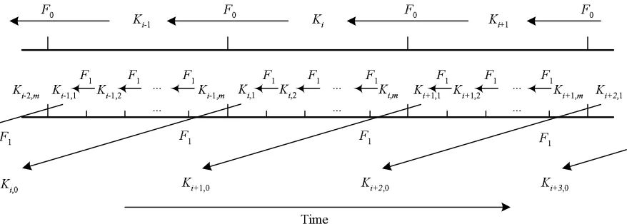
Figure 1: The two levels of key chains in Scheme II. Each keyKi is used for the high-level time interval
Ii, and each key Ki,j is used for the low-level time interval Ii,j. F0 and F1 are different pseudo random functions. Each commitmentKi,0 is distributed during the time intervalIi−2.
F1.
Thus, to use a low-level key chainhKi,0iduringIi, the base station needs to generate the key chain during
Ii−2 and distributeKi,0inCDMi−2.
Since the high-level authentication keyKi is disclosed inCDMi+1 during the time intervalIi+1, each sensor needs to storeCDMiuntil it receivesCDMi+1. Each sensor also stores a keyKj, which is initially
K0. After receiving Ki−1 inCDMi, the sensor authenticates it by verifying that Fi
−1−j
1 (Ki−1) = Kj.
Then the sensor replaces the currentKjwithKi−1.
Suppose a sensor has received CDMi−2. Upon receiving CDMi−1 during Ii−1, the sensor can au-thenticate CDMi−2 with Ki−2 disclosed in CDMi−1, and thus verify Ki,0. As a result, the sensor can
authenticate broadcast messages sent by the base station using theµTESLA key chain hKi,0i during the high-level time intervalIi.
This scheme uses µTESLA in two different levels. The high-level key chain relies on the initializa-tion phase of the sensor nodes to distribute the key chain commitment, and it only has a single key chain throughout the lifetime of the sensor network. The low-level key chains depend on the high-level key chain to distribute and authenticate the commitments. Figure 1 illustrates the two-level key chains, and Figure 2 displays the key disclosure schedule for the keys in these key chains.
The two-level key chains scheme mitigates the problem encountered in scheme I. On the one hand, by having long time intervals, the high-level key chain can cover a long period of time without having a very long key chain. On the other hand, the low-level key chain has short time intervals so that authentication of broadcast messages doesn’t have to be delayed too much.
Similar toµTESLA and TESLA, a sensor can detect forged messages by verifying the MAC with the cor-responding authentication key once the sensor receives it. In addition, replay attacks can be easily defeated if a sequence number is included in each message.
3.2.1 Discussion
!"# $ %"&'()&*+$ ),
()- .($/$(0$1&
% "&'()&*+$ ),
2 "3
2
.($/$( 0$1 &
%"&4+"5*4")6 ),
()- .($/$(')# # "4# $64&
7 *4 2
$64"'84")6 ),
()- .($/$(')# # "4# $64&
Figure 2: Key disclosure schedule in Scheme II
remove this delay. Specifically, by directly using the immediate authentication extension, we may construct theCDMimessage for the high-level time intervalIias follows:
CDMi = i|Ki+1,0|H(Ki+2,0)|M ACK′
i(i|Ki+1,0|H(Ki+2,0)) |Ki−1, where “|” denotes message
concatenation, H is a pseudo random function other than F0 and F1, and Ki′ is derived from Ki
with a pseudo random function other thanH,F0andF1.
Suppose a sensor has receivedCDMi−2. Upon receivingCDMi−1, the sensor can authenticateCDMi−2 withKi−2disclosed inCDMi−1. Then the sensor can immediately authenticateKi,0by verifying that ap-plyingHtoKi,0inCDMi−1results in the sameH(Ki,0)included inCDMi−2. As a result, the sensor can authenticate a low-level key chain commitment immediately after receiving it.
A closer look at this approach reveals that it is not as desirable as it appears to be. In the original proposal in [16], it makes perfect sense to include the image (under a pseudo random function) of a message that will be transmitted later, since a message in general is much longer than a hash image. However, in our application, the image of a key is usually as long as the original key, and including the image of a key (i.e.,
H(Ki+2,0)) doesn’t save much space compared with including the key (i.e.,Ki+2,0) itself. Thus, we may
construct theCDMiforIi as follows:
CDMi =i|Ki+1,0|Ki+2,0|M ACK′
i(i|Ki+1,0|Ki+2,0)|Ki−1, where “|” denotes message
concatena-tion, andK′
i is derived fromKiwith a pseudo random function other thanF0 andF1.
This CDMi message is indeed very close to our initial design; the only difference is that each
low-level key chain commitment is included in two consecutive CDM messages. We can certainly include the same key chain commitment in differentCDM messages; however, this will increase the size of theCDM
message. Considering the fact that packets in distributed sensor networks usually have limited size (e.g., the payload of each packet in TinyOS [10] is at most 29 bytes), we decide not to include multiple key chain commitments in oneCDMmessage.
9 :;< 9 : 9:=<
>>> 9 :;<
? < 9 :;<
?@
9 :;<
?A 9:
? < 9 :
?@
9 :
?A 9 :B<
? < 9 :B<
?@
9 :B<
?A
>>> >>>
9:;
@?A C
D<
C D< C D<
C D<
C < C < C < C < C < C < C < C < C <
>>>
>>> >>>
EFG H 9:
? D
9 :B<
?
D 9 :BI
?
D 9 :BJ
? D C <
C < C <
C <
9 :BI
? <
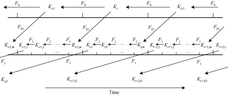
Figure 3: The two levels of key chains in Scheme III. It differs from Figure 1 in that each Ki,m is derived
fromKi+1using an additional pseudo random functionF01.
3.3 Scheme III: Fault Tolerant Two-LevelµTESLA
Scheme II does not tolerate message loss as well asµTESLA and TESLA. There are two types of message losses: the loss of normal messages, and the loss ofCDMmessages. Both may cause problems for scheme II. First, the low-level keys are not entirely chained together. Thus, loss of key disclosure messages for later keys in a low-level key chain cannot be recovered even if the sensor can receive keys in some later low-level key chains. As a result, a sensor may not be able to authenticate a stored message even if it receives some key disclosure messages later. In contrast, with µTESLA a receiver can authenticate a stored message as long as it receives a later key. Second, ifCDMi−2does not reach a sensor, the sensor will not be able to use the key chainhKi,0ifor authentication during the entire time intervalIi, which is usually long enough
to make the high-level key chain short.
To address the first problem, we propose to further connect the low-level key chains to the high-level one. Specifically, instead of choosing each Ki,m randomly, we derive each Ki,m from a high-level key Ki+1,
which is to be used in the next high-level time interval, through another pseudo random functionF01. That is,Ki,m =F01(Ki+1). As a result, a sensor can recover any authentication keyKi,j as long as it receives a
CDM message that disclosesKi′ withi′>=i+ 1, even if it does not receive any later low-level keyKi,j′
withj′
>=j. Thus, the first problem can be resolved. Figure 3 illustrates this idea.
The second problem does not have an ultimate solution; if the base station cannot reach a sensor at all during a time interval Ii, CDMi will not be delivered to the sensor. However, the impact of temporary
communication failures can be reduced by standard fault tolerant approaches.
To mitigate the second problem, we propose to have the base station periodically broadcast the CDM
message during each time interval. Assuming that the frequency of this broadcast isF, eachCDM message is therefore broadcasted F ×∆0 times. To simplify the analysis, we assume the probability that a sensor cannot receive a broadcast of aCDM message ispf. Thus, the probability that a sensor cannot receive any
copy of theCDMmessage is reduced topF×∆0
f .
Note that even if a sensor cannot receive any CDM message during a time interval Ii, it still has the
opportunity to authenticate broadcast messages in time intervals later than Ii+1. Not having the CDM
By periodically broadcasting CDM messages, scheme III introduces more overhead than scheme II. Let’s consider the overhead on the base station, the sensors, and the communication channel, respectively. Compared with Scheme II, this scheme increases the overhead of the base station byF ×∆0 times. Base stations in a sensor network are usually much more powerful than the sensor nodes. Thus, the increased overhead on base stations may not be a big problem as long asF×∆0is reasonable.
The sensors are affected much less than the base station in a benign environment, since each sensor only needs to process oneCDM message for each time interval. Thus, the sensors have roughly the same overhead as in scheme II. However, we will show that a sensor has to take a different strategy in a hostile environment in which there are DOS attacks. We will delay the discussion of sensors’ overhead until we introduce our counter measures.
The overhead on the communication channel is increased byF×∆0times, since theCDM message for each time interval is repeatedF ×∆0 times. Assume the probability that a sensor cannot receive a CDM message ispf = 1/2and F ×∆0 = 10. Under our simplified assumption, the probability that the sensor cannot receive any of the 10CDMmessages ispF×∆0
f <0.1%. Further assume that∆0is 1 minutes, which
is quite short as the interval length for the high-level key chain. Thus, there is one CDM message per 6 seconds. Assume the bandwidth is 10 kbps and eachCDM packet is 36 bytes = 288 bits, which includes the 29 byteCDMmessage and the 7 byte packet header as in our experiments (Section 5). Then the relative communication overhead is 10240288×6 = 0.47%. This is certainly optimistic, since we assume perfect channel utilization. However, it still shows that scheme III introduces very reasonable communication overhead in typical sensor networks.
One limitation of Scheme III is that if a sensor misses all copies ofCDMi during the time interval Ii,
it cannot authenticate any data packets received duringIi+2before it receives an authentic Kj,j > i+ 2.
(Note that the sensor does not have to receive an authentic CDM message. As long as the sensor can authenticate a high-level keyKj withj > i+ 2, it can derive the low-level keys through the pseudorandom
functions F0 andF01.) Since the earliest high-level keyKj that satisfiesj > i+ 2 isKi+3, andKi+3 is disclosed duringIi+4, the sensor has to buffer the data packets received duringIi+2for at least the duration of one high-level time interval.
3.4 Scheme IV: DOS-Tolerant Two-LevelµTESLA
In scheme III, the usability of a low-level key chain depends on the authentication of the key chain commit-ment contained in the corresponding CDM message. A sensor cannot use the low-level key chainhKi,0i for authentication before it can authenticateKi,0distributed inCDMi−2. This makes theCDM messages attractive targets for attackers. An attacker may disrupt the distribution ofCDM messages, and thus pre-vent the sensors from authenticating broadcast messages during the corresponding high-level time intervals. Although the high-level key chain and the low-level ones are chained together, and such sensors may store the broadcast messages and authenticate them once they receive a later commitment distribution message, the delay between the receipt and the authentication of the messages may introduce a problem: Indeed, an attacker may send a large amount of forged messages to exhaust the sensors’ buffer before they can authenticate the buffered messages, and force them to drop some authentic messages.
sends theCDMmessages randomly.
An attacker may forge commitment distribution messages to confuse the sensors. If a sensor does not have a copy of the actualCDMi, it will not be able to get the correctKi+2,0, and cannot use the low-level key chainhKi+2,0iduring the time intervalIi+2.
Consider a commitment distribution message: CDMi = i|Ki+2,0|M ACK′
i(i|Ki+2,0)|Ki−1. Once
see-ing such a message, the attacker learns i and Ki−1. Then the attacker can replace the actual Ki+2,0 or M ACK′
i(i|Ki+2,0) with arbitrary values K
′
i+2,0 or M AC ′
, and forge another message: CDM′
i =
i|K′
i+2,0|M AC ′
|Ki−1. Assume a sensor has an authentic copy ofCDMi−1. The sensor can verify Ki−1 withKi−2, sinceKi−2is included inCDMi−1. However, the sensor has no way to verify the authenticity ofK′
i+2,0orM AC ′
without the corresponding key, which will be disclosed later. In other words, the sensor cannot distinguish between the authenticCDMi messages and those forged by the attacker. If the sensor
does not save an authentic copy ofCDMiduringIi, it will not be able to get an authenticatedKi+2,0 even if it receives the authentication keyKiinCDMi+1duringIi+1. As a result, the sensor cannot use the key
chainhKi+2,0iduringIi+2.
One may suggest to distribute eachKi,0 in some earlier time intervals thanIi−2. However, this doesn’t solve the problem. If a sensor doesn’t have an authentic copy of theCDM message, it can never get the correctKi,0. To take advantage of this, an attacker can simply forgeCDM messages as discussed earlier.
We propose a random selection method to improve the reliable broadcast of commitment distribution messages. For theCDMi messages received during each time intervalIi, each sensor first tries to discard
as many forged messages as possible. There is a simple test for a sensor to identify some forged CDMi
message duringIi. The sensor can verify ifFi
−1−j
0 (Ki−1) =Kj, whereKi−1is the high-level key disclosed inCDMi and Kj is a previously disclosed high-level key. (Note that such aKj always exists, since the
commitment K0 of the high-level key chain is distributed during the initialization of the sensor nodes.) Messages that fail this test are certainly forged and should be discarded.
The simple test can filter out some forged messages; however, they do not rule out the forged messages discussed earlier. To further improve the possibility that the sensor has an authentic CDMi message, the
base station uses a random selection method to store theCDMimessages that pass the above test. Our goal
is to make the DOS attack so difficult that the attacker would rather use constant signal jamming instead to attack the sensor network. Some of the strategies are also applicable to the low-level key chains as well as the (extended) TESLA andµTESLA protocols.
Without loss of generality, we assume that each copy of CDMi has been weakly authenticated in the
time intervalIiby using the aforementioned test.
3.4.1 Single Buffer Random Selection
Let us first look at a simple strategy: single buffer random selection. Assume that each sensor node only has one buffer for theCDM message broadcasted in each time interval. In a time intervalIi, each sensor node
randomly selects one message from all the copies ofCDMi. The key issue here is to make sure all copies
ofCDMi have equal probability to be selected. Otherwise, an attacker who knows the protocol may take
advantage of the unequal probabilities and make a forgedCDMmessage be selected.
To achieve this goal, for the kth copy ofCDMi a sensor node receives during the time interval Ii, the
sensor node saves it in the buffer with probability 1k. Thus, a sensor node will save the first copy ofCDMi
in the buffer, substitute the second copy for the buffer with probability1/2, substitute the third copy for the buffer with probability1/3, and so on. It is easy to verify that if a sensor node receivesncopies ofCDMi,
all copies have the same probability1/nto be kept in the buffer.
1−p, wherep= ##f orged copiestotal copies . To maximize his attack, an attacker has to send as many forged copies as possible.
3.4.2 Multiple Buffer Random Selection
The single buffer random selection can be easily improved by having some additional buffers for theCDM
messages. Assume there are m buffers. During each time interval Ii, a sensor node can save the first m
copies ofCDMi. For thekth copy withk > m, the sensor node keeps it with probability mk. If a copy is
to be kept, the sensor node randomly selects one of thembuffers and replaces the corresponding copy. It is easy to verify that if a sensor node receivesncopies ofCDMi, all copies have the same probability mn to
be kept in one of the buffers.
During the time interval Ii+1, the sensor node can verify if it has an authentic copy of CDMi once
it receives and weakly authenticates a copy of CDMi+1. Specifically, the sensor node uses the key Ki
disclosed inCDMi+1to verify the MAC of the buffered copies ofCDMi. Once it finds an authentic copy,
the sensor node can discard all the other buffers.
If the sensor node cannot find an authentic copy ofCDMi after the above verification, it can conclude
that all buffered copies ofCDMiare forged and discard all of them. The sensor node then needs to repeat
the random selection process for the copies ofCDMi+1. Thus, a sensor node needs at mostm+ 1buffers forCDM messages with this strategy: mbuffers for copies ofCDMi, and one buffer for the first weakly
authenticated copy ofCDMi+1.
With m buffer random selection strategy, the probability that a sensor node has an authentic copy of
CDMican be estimated asP(CDMi) = 1−pm, wherep= ##f orged copiestotal copies .
3.5 Scheme V: DOS-Resistant Two-LevelµTESLA
Scheme IV can be further improved if the base station has enough computational and storage resources. Indeed, when all theCDM messages can reach the sensors, we can completely defeat the aforementioned DOS attack without the random selection strategies.
The solution can be considered a variation of the immediate authentication extension to TESLA [16]. The idea is to include in CDMi the image H(CDMi+1) ofCDMi+1 for each i, where H is a pseudo random function. As a result, if a sensor can authenticate CDMi, it can get authenticH(CDMi+1)and thus authenticateCDMi+1when it’s received. Specifically, the base station constructsCDMifor the
high-level time intervalIias follows:
CDMi = i|Ki+1,0|H(CDMi+1)|M ACK′
i(i|Ki+1,0|H(CDMi+1))|Ki−1, where “|” denotes
mes-sage concatenation,His a pseudo random function other than F0andF1, andKi′is derived fromKi
with a pseudo random function other thanH,F0andF1.
Suppose a sensor has received CDMi. Upon receiving CDMi+1, the sensor can authenticate CDMi
withKi disclosed inCDMi+1. Then the sensor can immediately authenticateCDMi+1 by verifying that applyingH toCDMi+1results in the sameH(CDMi+1)included inCDMi. As a result, the sensor can
authenticate a commitment distribution message immediately after receiving it.
The cost, however, is that the base station has to compute theCDM messages in the reverse order. That is, in order to includeH(CDMi+1)inCDMi, the base station has to haveCDMi+1, which implies that it
also needsCDMi+2, and so on. Therefore, the base station needs to compute both the high-level and the low-level key chains completely to get the commitments of these key chains, and construct all the CDM
This imposes substantial computation during the initialization phase, and storage requirements during the lifetime of a sensor network at the base station. Assume that all the key chains have 1,000 keys, and both the authentication key and the image of a key are 8 byte long. The base station needs to perform about 1,001,000 pseudo random function operations to generate all the key chain commitments, and 1,000 pseudo random function operations and 1,000 MAC operations to generate all the CDM messages. Even if the base station doesn’t save the immediate values for the sake of space, it still needs to store the MAC of all theCDM messages, which will take8×1,000 = 8,000bytes.
The immediate authentication ofCDMidepends on the successful receipt ofCDMi−1. However, if a sensor cannot receive an authentic CDMidue to communication failure or an attacker’s active disruption,
the sensor has to fall back to the techniques introduced in Scheme IV (i.e., the random selection strategies). This implies that the base station still needs to distribute CDM messages multiple times and in a random manner. The combination of these techniques is straightforward. Thus, we do not discuss it further in this paper.
From the above analysis, we can see that this scheme introduces substantial precomputation and stor-age overhead, though it can defeat the DOS attacks when there is no communication failures. Comparing schemes IV and scheme V, we believe both of them are useful. The choice depends the availability of the resources in the sensors and the base station.
3.6 Scheme VI: Multi-LevelµTESLA
Both scheme IV and scheme V can be easily extended to m-level key chain schemes. Them-level key chains are arranged from level 0 to levelm−1from top down. The keys in the (m−1)-level key chains are used for authenticating data packets. Each higher-level key chain is used to distribute the commitments of the immediately lower-level key chains. Only the last key of the top-level (level 0) key chain needs to be selected randomly; all the other keys in the top-level key chain can be generated from this key, and all the key chains in leveli,1< i ≤m−1, are generated from the keys in leveli−1, in the same way that the low-level key chains are generated from the high-level keys in the two-level key chain schemes. For security concern, we need a family of pseudo random functions. The pseudo random function for each level and between adjacent levels should be different from each other. Such a family of pseudo random functions has been proposed in [15].
The benefit of having multi-level key chains is that it requires less number of keys in each key chain, or equivalently, shorter duration at each key chain level, compared with the two-level key chain schemes. As a result, the multi-levelµTESLA scheme can scale up to long period of time.
Due to the adoption of schemes IV and V, we have two variations of multi-level µTESLA schemes. The first variation, DOS-tolerant multi-level µTESLA, which is extended from scheme IV, is suitable for
applications where the base station is not very resourceful, while the second variation, DOS-resistant
multi-levelµTESLA, which is extended from scheme V, is suitable for applications where the base station is very
resourceful in terms of computational power and storage space.
3.6.1 Variation I: DOS-Tolerant Multi-LevelµTESLA
This variation of multi-levelµTESLA scheme is a simple extension to scheme IV. Similar to scheme IV, we also use multiple buffer random selection mechanism for the buffering ofCDMmessages.
will not have higher percentage of forged CDM messages than scheme IV. The base station can further piggy-back theCDMmessages for different levels of key chains so as to reduce the communication cost.
Having more levels of key chains does increase the overhead at both the base station and the sensor nodes. This variation requires the base station maintain one active key chain at each level. Because of the avaiable resource at typical bases stations, this overhead is usually tolerable. Similarly, sensor nodes have to maintain more buffers for the key chain commitments as well asCDM messages in different levels. This is usually not desirable because of the resource constraints at sensors. In addition, the more levels we have, the more bandwidth is required to transmit the CDM messages. Thus, we should use as few levels as possible to cover the lifetime of a sensor network.
3.6.2 Variation II: DOS-Resistant Multi-LevelµTESLA
Directly extending scheme V to multi-levelµTESLA scheme increases the performance overhead signifi-cantly. Assume each key chain has 1,000 keys. Using 4-level key chains implies that the base station needs to precompute and store about 1,001,001,000 images ofCDM messages under a pseudo random function. In general, the number of such images is roughly linear to the number of (m −2)-level time intervals. Obviously, such a method does not scale well to long-lived sensor networks.
To make this variation practical, we adopt a trade-off to reduce the computational overhead (during initial-ization) and the space overhead greatly by sacrificing certain immediate authentication capability. Specifi-cally, we may limit the precomputedCDM messages to the active key chain being used in each level. For a given key chain in a particular level, the base station computes the images of theCDM messages (under the pseudo random function H) only when the first key is needed for authentication, and this computation does not go beyond this key chain in this level. As a result, theCDM message authenticated with the last key in a key chain will not include the image of the nextCDM message in the same level, because this information is not available yet. The base station may simply set this field as NULL. For the first key chain in each levell, where 0 ≤l < m−1, the image of the firstCDM message can be distributed during the initialization phase.
The behavior of a sensor is still very simple. If the sensor has an authentic image of the nextCDM mes-sage in a certain level, it can authenticate the nextCDMmessage immediately after receiving it. Otherwise, the sensor simply uses the random selection strategy to buffer the weakly authenticated copies. To increase the chance that the sensors receive an authentic image of the firstCDM message related to key chain, the base station may also broadcast it in data packets.
Such a method reduces the storage requirement significantly. For anm-level µTESLA with nkeys in each key chain, the base station only needs to store(m−1)·nimages of CDM messages. In the earlier example with 4-level key chains and 1,000 keys per key chain, the base station only needs to store 3,000 (instead of 1,001,001,000)CDM images.
4
Multi-Level
µ
TESLA on TinyOS
We have implemented the DOS-tolerant multi-levelµTESLA scheme on TinyOS [10], which is an operating system for networked sensors. The software package can be downloaded on our website1.
We cannot directly implement the DOS-resistant multi-level µTESLA scheme on TinyOS due to the maximum payload size (29 bytes) supported by TinyOS. It might be possible to implement the DOS-resistant multi-levelµTESLA scheme by transmitting aCDM message over multiple packets, or modify TinyOS to
1
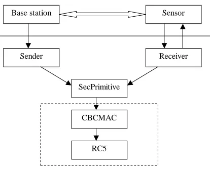
Sender Receiver
SecPrimitive
CBCMAC
RC5
Base station Sensor
Figure 4: The multi-levelµTESLA broadcast authentication system on TinyOS.
support larger packets; however, we do not pursue such methods in this paper, but consider them possible future work.
Following [17], we implemented pseudo random functions with a MAC, which was implemented using the CBC-MAC [22] with RC5 as the block cipher [18]. Our implementation uses RC5 with 32 bit words, 12 rounds, and 8 byte keys.
In our system, the number of levels, denotedM AX LEV EL, is predetermined at the compiling time. The type of a packet, which is either a data packet or aCDM packet, is indicated by the first byte in the packet. (M AX LEV EL−1)indicates that the packet is a data packet, while other smaller, non-negative integer indicates that the packet is aCDM packet in the corresponding level.
EachCDM packet consists of the following fields: level (1 byte), index (of time interval) (4 bytes), key chain commitment (8 bytes), MAC (8 bytes), and disclosed key (8 bytes). Thus, the total length of aCDM
message is 29 bytes. It is easy to see that this is already the maximum payload size supported by TinyOS. The DOS-resistant variation of the multi-levelµTESLA scheme requires an additional field of image of next
CDM message (8 bytes), and thus cannot be directly accommodated by TinyOS. Details aboutCDM as well as data packets can be found in Appendix B.
The architecture of the broadcast authentication system is illustrated in Figure 4. The system consists of 5 components: RC5, CBCMAC, SecPrimitive, Sender, and Receiver. The components in the dashed box, RC5 and CBCMAC, are directly adopted from the TinySec package2. The SecPrimitive component, which is developed based on the CBCMAC component, provides security primitives, including pseudo random function, pseudo random number generator, generation of key chains, and generation and verification of MAC.
The Sender and the Receiver components are intended to provide broadcast authentication services for the base station application and the sensor application, respectively, using the interfaces provided by the SecPrimitive component. The application in the base station may call the corresponding interfaces in the Sender component to initialize the system, or generate authenticated CDM packets or data packets. Sim-ilarly, the application in a sensor node may call the interfaces in the Receiver component to initialize the system, or process newly received CDM or data packet. Whenever a data packet is authenticated, the Receiver component triggers an event to pass the authentic data packet to the sensor application.
We use the multiple buffer random selection strategy at the sensors to deter DOS attacks against the
CDM packets. To simplify the buffer management at the resource constrained sensors, we choose to
2
predetermine the number of data and CDM buffers. The sensor application may decide these numbers during the initialization phase. The numbers of data andCDMbuffers are certainly important to the overall performance. In Section 5, we perform a series of experiments to show how these parameters may be selected to deter intensive DOS attacks.
4.1 Multi-LevelµTESLA API
Our broadcast authentication system provides a simple and easy-to-use API for base station as well as sensor applications. The API for base stations is contained in the Sender component, while the API for sensors is provided in the Receiver component. This API is independent of the communication module, and thus can be used along with different types of base stations and sensors. In this subsection, we first present the API, and then discuss how to build applications based on this API. The details of data structures and functions in this API can be found in Appendix B.
4.1.1 The Sender Component
The Sender component provides the following functions:
1. Sender.init: It initializes the sender based on the given configuration, which includes the master key used to generate all the key chains, the length of the key chains and the durations of time intervals in each level, the start time of multi-level µTESLA protocol, and the key disclosue lag of the data packet.
2. Sender.generateCDM: It generates a CDM packet for a given level at a given time and puts the generatedCDMpacket in the buffer provided by the caller. It is caller’s responsibility to deliver this packet.
3. Sender.authenticateData: It generates a MAC for a given data packet. The caller needs to fill in the data payload field in the data packet. This function then fills in all the other fileds, including the level (indicating a data packet), the index of current time interval for the lowest-level key chain, MAC, and the disclosed key for an earlier time interval. Similar to the first function, it is the caller’s responsibility to deliver this packet.
4. Sender.generateConf: It generates the configuration parameters for the receivers that will receive the authentic packets from this particular sender. The configuration parameters include the length of the key chains as well as the duration of time intervals in each level, the start time of multi-levelµTESLA protocol, the key disclosue lag of the data packet, the commitments of the first key chain in all levels, and the commitments of the second key chain in all levels other than level 0. We assume that there are other ways to derive the maximum clock discrepency and maintain loose time sychronization between the sender and the receivers. These configuration parameters should be given to the receivers through a secure channel that can ensure the integrity of these parameters.
4.1.2 The Receiver Component
The Receiver component provides the following 4 functions:
1. Receiver.init: It initializes the receiver based on a given configuration, which includes the length of the key chains as well as the duration of time intervals in each level, the start time of multi-level
all levels, the commitments of the second key chain in all levels other than level 0, and the maximum clock discrepancy.
2. Receiver.ProcessCDM: This is the main function used to update the key chain commitments. It first performs security check on the newly received CDM packet. If the packet is safe and the disclosed key is verified, it verifies the buffered CDM packet using the authenticated disclosed key. During this time, it updates the key chain commitment if new authentic key commitment is discovered.
3. Receiver.ProcessData: This is the main function that used to process the newly received data packet. It first checks the security condition of this packet and the authenticity of the disclosed key in this packet. If this check succeeds, it authenticates the buffered data packets and also buffer the received packet.
4. Receiver.authenticDataReady: This is an event in TinyOS; it is signaled whenever a data packet is authenticated to pass the authenticated data packet to the receiver application. The sensor application must implement an event handler to process the authenticated data packet.
4.1.3 Building Applications Based on Multi-LevelµTESLA API
We use a simple example to show how to build an application with broadcast authentication for base stations and sensors, respectively, using the Sender and the Receiver components. To facilitate our presentation, we assume there is a simple communication module named COMM, which has the following three functions:
• COMM.init: Initialize the communication module.
• COMM.send: Send a packet in the communication channel.
• COMM.receive: Typically, this is implemented as an event in TinyOS. It triggers the event handler in the application to pass the packet it receives from the communication channel.
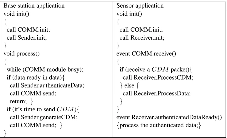
Figure 5 shows example base station as well as sensor applications. For brevity, the arguments of function calls are omitted. As shown in the left column, a typical base station application has the following steps:
1. Initialization: The base station application calls COMM.init and Sender.init to initialize the Sender and the communication components.
2. Sending a data packet: The base station first needs to ensure that the communication component is not in busy state. It also checks whether the data are ready or not. If the data are ready, the application calls Sender.authenticateData to fill in the authentication information, and then calls COMM.send to send the packet out.
3. Sending aCDM packet: The base station first needs to ensure that the communication component is not in busy state. If it is also the time to send aCDM packet for a particular level, the application calls Sender.generateCDM to generate theCDM packet, and then calls COMM.send to send out this
CDMpacket.
The right column of Figure 5 shows a typical sensor application, which has the following steps.
Base station application Sensor application
void init() void init()
{ {
call COMM.init; call COMM.init; call Sender.init; call Receiver.init;
} }
void process() event COMM.receive()
{ {
while (COMM module busy); if (receive aCDMpacket){
if (data ready in data){ call Receiver.ProcessCDM; call Sender.authenticateData; }else{
call COMM.send; call Receiver.ProcessData;
return; } }
if (it’s time to sendCDM){ }
call Sender.generateCDM; event Receiver.authenticatedDataReady() call COMM.send; } {process the authenticated data;}
}
Figure 5: Example applications in base stations and sensor nodes.
2. Receiving a packet: If a new packet is received from the communication channel, the communication component triggers an event COMM.received to pass the new packet to the sensor application. The sensor application needs to implement an event handler to process the received packet.
3. Processing the packet: When the application is notified for a newly received packet, it checks the type of this packet, and passes it to either Receiver.ProcessData or Receiver.ProcessCDM function.
4. Processing the authenticated data Packet: Whenever a data packet is authenticated, the receiver com-ponent triggers an event to pass the authenticated data packet to the sensor application. The sensor application needs to implement an event hander function to process the received data packet.
5
Experimental Results
We have performed a series of experiments to evaluate the performance of the DOS-tolerant multi-level
µTESLA when there are packet loss and DOS attacks againstCDMmessages. The focus of the evaluation is on the overall effectiveness of the proposed techniques (e.g., multi-buffer random selection) in tolerating packet loss and DOS attacks, and the impact of different choices of certain parameters (e.g., buffer size, percentage of forgedCDM packets). The experiments were performed using Nido, the TinyOS simulator. To simulate the lossy communication channel, we have each sensor drop each received packet with a given probability.
To further study the performance of the scheme in presence of attacks, we also implemented an attacker component, which listens to theCDMmessages broadcasted by the base station and inserts forged CDM
Since they are either defeatable by the scheme (e.g., modification of data packets), or not specific to our extension (e.g., DOS attacks against the data packets), we did not consider them in our experiments.
To concentrate on the design decisions we made in our schemes, we fix the following parameters in all the experiments. We only performed the experiments with DOS-tolerant two-levelµTESLA, since the only purpose of having multiple levels is to scale up to long period of time. We assume the duration of each low-level time interval is 100 ms, and each low-level key chain consists of 600 keys. Thus, the duration of each time interval for the high-level key chain is 60 seconds. We put 200 keys in the high-level key chain, which covers up to 200 minutes in time. We also set the data packet rate at base station to 100 data packets per minute. Our analysis and experiments indicate that the number of high-level keys does not have an obvious impact on the performance measures. Nevertheless, the lifetime of the two-level key chains can be extended by having more keys in the high-level key chain or another higher level of key chain. Since our purpose is to study the performance of the scheme w.r.t. to packet loss and DOS attacks, we did not do so in our evaluation.
The performance of our system is evaluated with the following metrics: average percentage of authenti-cated data packets (i.e., #authenticated data packets#received data packets averaged over the sensor nodes) and average data packet authentication delay (i.e., the average time between the receipt and the authentication of a data packet). In these experiments, we focused on the impact of the following parameters on these performance metrics: sensor node’s buffer size for data andCDM messages, percentage of forgedCDM packets and the packet loss rate.
Because of the extremely limited memory available on sensor nodes, the buffer allocation for data packets and CDM messages becomes a major concern when we deploy a real sensor network. We evaluate the performance of different memory allocation schemes with a memory constraint. Due to the limitation on the size of payload in TinyOS active message, in our implementation, bothCDM and data packets consist of 29 bytes. The data packet includes a level number (1 bytes), an index (4 bytes), data (8 bytes), MAC (8 bytes) and a disclosed key (8 bytes). ACDM packet includes a level number (1 byte), an index (4 bytes), a key commitmentKi+2,0 (8 bytes), a MAC (8 bytes), and a disclosed key (8 bytes).
When a sensor node receives a data packet, it does not need to buffer the level number and the disclosed key for future authentication; only the other 20 bytes need to be stored. ForCDM packets, all copies of the sameCDM message have the same values for the fields other than the key commitment and the MAC value (i.e.,Ki+2,0and MAC inCDMi), since all forged messages without these values can be filtered out
by the weak authentication mechanism. As a result, for all copies ofCDMi, the only fields that need saving
areKi+2,0(8 bytes) and MAC (8 bytes), assuming that the level number and the index are used to locate the buffer and the disclosed keyKi−1 is stored elsewhere to authenticate later disclosed keys. Further assume the totally available memory for data andCDM messages isCbytes, and the sensor node decides to store up toxdata packets. Then the sensor can save up toy=⌊C−20×x
16 ⌋copies ofCDM messages.
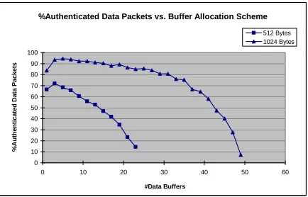
Figure 6 shows the performance of different memory allocation schemes under severe DOS attacks against CDM messages (95% forged CDM packets). In these experiments, we have total memory of 512 bytes or 1K bytes. As in Figure 6, three data buffers (60 bytes) are enough to authenticate over 90% of the received data packets when the total memory is 1K bytes. The figure also shows that after a certain point, having more data buffers does not increase the performance. On the contrary, it decreases the performance, since less memory is left for buffering theCDM messages.
%Authenticated Data Packets vs. Buffer Allocation Scheme
0 10 20 30 40 50 60 70 80 90 100
0 10 20 30 40 50 60
#Data Buffers
%
A
u
th
e
n
ti
c
a
te
d
D
a
ta
P
a
c
k
e
ts
512 Bytes 1024 Bytes
Figure 6: The performance with different buffer allocation schemes for total memory 512 and 1024 bytes to buffer data andCDMmessages. Assume 95% ofCDMpackets are forged and 50% of packets are lost when transmitted over the channel.
an authenticCDM message if all of theCDM messages it receives are forged. Nevertheless, an attacker has to make sure he/she sends much more forged CDMpackets than the authentic ones to increase his/her chance of success.
Figure 7(a) also shows that if the base station rebroadcasts sufficient number ofCDMmessages so that on average, at least one copy of such authenticCDMmessage can reach a sensor node in the corresponding high-level time interval (e.g., when loss rate ≤ 70%), the channel loss rate does not affect our scheme much. When the loss rate is large (e.g., 90% as in Figure 7(a)), we can observe the drop of data packet authentication rate when the percentage of forgedCDM packets is low.
An interesting result is that when the channel loss rate is 90%, the data packet authentication rate initially increase when the percentage of forgedCDM packets increases. This is because the sensor nodes can get the disclosed key from forgedCDMpackets when they cannot get it from the authentic ones.
The channel loss rate does affect the average authentication delay, which can be seen in Figure 7(b). The reason is that a sensor node needs to wait longer time to get the disclosed key. In addition, the figure also shows that the percentage of forgedCDM message does not have an significant impact on the average data packet authentication delay.
In summary, the experimental results demonstrate that our system can maintain reasonable performance even with high channel loss rate under severe DOS attacks.
6
Related Work
Security issues such as broadcast authentication have been investigated by other researchers [21, 6, 17]. Due to the limited resources at sensor nodes, asymmetric cryptography based solutions [8, 20, 23] are usually impractical for sensor networks. In the following, we only review authentication schemes based on symmetric cryptography.
Cheung proposed a scheme named OLSV based on delayed disclosure of keys by the sender to authen-ticate the link-state routing updates between routers [7]. Anderson et al. used the same technique in their Guy Fawkes protocol to authenticate the message between two parties [1]. However, their protocol cannot tolerate packet loss. Briscoe proposed the FLAMeS protocol [4], and Bergadano et al. presented an authenti-cation protocol for multicast [3]. Both are similar to the OLSV protocol [7]. Canetti et al. proposed to usek
%Authenticated Data Packets vs. %Forged CDM Packets 0 20 40 60 80 100 120
0 20 40 60 80 100
%Forged CDM Packets
% A u th e n ti c a te d D a ta P a c k e ts
0.1 Loss Rate 0.3 Loss Rate 0.5 Loss Rate 0.7 Loss Rate 0.8 Loss Rate 0.9 Loss Rate
(a) Percentage of authenticated data packets
Average Data Packet Authentication Delay vs. Channel Loss Rate 0 2 4 6 8 10 12 14
0 10 20 30 40 50 60 70 80 90 100
Channel Loss Rate
A v e ra g e D a ta P a c k e t A u th e n ti c a ti o n D e la y (s e c o n d s )
20% Forged CDM Packets 50% Forged CDM Packets 99% Forged CDM Packets
(b) Average data packet authentication delay
Figure 7: Experimental results under different channel loss rate and percentage of forged CDM packets. Assuming 3 data packet buffers, 39CDMbuffers and fixed data rate (100data packets/minute).
introduced a verification efficient signature scheme named BiBa based on one-way hash functions without trapdoors. The drawback of this scheme is its high signature generation and large communication overhead for public key distribution.
Perrig et al. proposed two schemes (TESLA and EMSS) for efficient multicast authentication over lossy channels [15]. TESLA requires loose time synchronization between sender and receiver, and does not provide non-repudiation. In contrast, EMSS does not require time synchronization, but introduces more signatures and communication overhead. Several extensions to TESLA, such as immediate authentication, multiple concurrent TESLA instances, were later proposed in [16]. TESLA requires a digital signature operation to bootstrap itself, which is impractical in resource constrained sensor networks. Instead of a digital signature, µTESLA [17] simply uses symmetric cryptography to distribute initial parameters to the sensor nodes individually. The drawback of this solution is its high communication overhead required for initializing sensors when the number of sensor nodes is large.
Perrig et al. proposed to use an earlier key chain to distribute the commitments of next one [14]. Multiple early TESLA packets are used to tolerate packet loss. However, since reliable distribution of later com-mitment cannot be fully guaranteed, if all the packets used to distribute comcom-mitments are lost (e.g., due to temporary network partition), a receiver cannot recover the commitment of the later key chain. As a result, the sender and the receivers will have to repeat the costly bootstrap process. In contrast, our multi-level commitment distribution scheme allows a receiver to recover the key chains even if all the commitment distribution messages during one high-level time interval are lost, due to the connection between the higher-and lower-level keys.
7
Conclusion and Future Work
In this paper, we developed a multi-level key chain scheme to efficiently distribute the key chain commit-ments for the broadcast authentication scheme namedµTESLA. By using pre-determination and broadcast, our approach removedµTESLA’s requirement of a unicast-based distribution of initial key chain commit-ments, which introduces high communication overhead in large distributed sensor networks. We also pro-posed several techniques, including periodic broadcast of commitment distribution messages and random selection strategies, to improve the survivability of our scheme and defeat some DOS attacks. The resulting protocol, named multi-levelµTESLA, satisfies several nice properties, including low overhead, tolerance of message loss, scalability to large networks, and resistance to replay attacks.
We also developed a broadcast authentication system on TinyOS, using the techniques proposed in this paper. Our system provides a simple and easy-to-use API, which can be used to build base station and sensor applications on TinyOS. Our experiments further demonstrated that the broadcast authentication system can tolerate message loss and DOS attacks to a certain degree.
The limitation of our scheme is that when a sensor node doesn’t get a key chain commitment during a time interval, it must wait for a relatively long period of time to recover from this failure. We will seek solutions to this problem in our future research.
References
[1] R. Anderson, F. Bergadano, B. Crispo, J. Lee, C. Manifavas, and R. Needham. A new family of authentication protocols. In Operating Systems Review, October 1998.
[2] S. Basagni, K. Herrin, D. Bruschi, and E. Rosti. Secure pebblenets. In Proceedings of ACM
Interna-tional Symposium on Mobile ad hoc networking and computing, pages 156–163, 2001.
[3] F. Bergadano, D. Cavagnino, and B. Crispo. Individual single source authentication on the mbone. In
ICME 2000, August 2000.
[4] B. Briscoe. FLAMeS: Fast, loss-tolerant authentication of multicast stream. Technical report, BT Research, 2000.
[5] R. Canetti, J. Garay, G. Itkis, D. Micciancio, M. Naor, and B. Pinkas. Multicast security: A taxonomy and some efficient constructions. In Proceedings of IEEE INFOCOMM, pages 708–716, 1999.
[6] D.W. Carman, P.S. Kruus, and B.J.Matt. Constrains and approaches for distributed sensor network security. Technical report, NAI Labs, 2000.
[7] S. Cheung. An efficient message authentication scheme for link state routing. In 13th Annual Computer
Security Applications conference, San Diego, Calif, December 1997.
[8] R. Gennaro and P. Rohatgi. How to sign digital streams. Technical report, IBM T.J.Watson Research Center, 1997.
[9] O. Goldreich, S. Goldwasser, and S. Micali. How to construct random functions. Journal of the ACM, 33(4):792–807, October 1986.
[11] H. Krawczyk, M. Bellare, and R. Canetti. HMAC: Keyed-hashing for message authentication. IETF RFC 2104, February 1997.
[12] D. Liu and P. Ning. Efficient distribution of key chain commitments for broadcast authentication in distributed sensor networks. In Proceedings of the 10th Annual Network and Distributed System
Security Symposium, pages 263–276, February 2003.
[13] A. Perrig. The BiBa one-time signature and broadcast authentication protocol. In Proceedings of the
ACM Conference on Computer and Communications Security, pages 28–37, November 2001.
[14] A. Perrig, R. Canetti, Briscoe, J. Tygar, and D. Song. TESLA: Multicast source authentication trans-form. IRTF draft, draft-irtf-smug-tesla-00.txt, November 2000.
[15] A. Perrig, R. Canetti, D. Song, and D. Tygar. Efficient authentication and signing of multicast streams over lossy channels. In Proceedings of the 2000 IEEE Symposium on Security and Privacy, May 2000.
[16] A. Perrig, R. Canetti, D. Song, and D. Tygar. Efficient and secure source authentication for multicast. In Proceedings of Network and Distributed System Security Symposium, February 2001.
[17] A. Perrig, R. Szewczyk, V. Wen, D. Culler, and J.D. Tygar. SPINS: Security protocols for sensor networks. In Proceedings of Seventh Annual International Conference on Mobile Computing and
Networks, July 2001.
[18] R. Rivest. The RC5 encryption algorithm. In Proceedings of the 1st International Workshop on Fast
Software Encryption, volume 809, pages 86–96, 1994.
[19] R.L. Rivest, A. Shamir, and L.A. Adleman. A method for obtaining digital signatures and public-key cryptosystems. Communications of the ACM, 21(2):120–126, 1978.
[20] P. Rohatgi. A compact and fast hybrid signature scheme for multicat packet authentication. In 6th
ACM Conference on Computer and Communications Security, November 1999.
[21] F. Stajano and R. Anderson. The resurrecting duckling: security issues for ad hoc networks. In Proc.
of Security Protocols: 7th International Workshop, pages 172–194, 1999.
[22] U.S. National Institute of Standards and Technology. DES modes of operation. Federal Information Processing Standards Publication 81 (FIPS PUB 4-3), December 1980.
[23] C.K. Wong and S. S. Lam. Digital signatures for flows and multicasts. In Proc. IEEE ICNP’98, 1998.
A
A Detailed Description of Scheme IV
Initialization
During the initialization phase, all the sensor nodes synchronize their clocks with the base station. (Al-ternatively, the base station and all the sensor nodes may synchronize their clocks with a time service.) In addition, the base station generates the following parameters: (1) the initial random key Knfor the
high-level key chain; (2) a sequence of keysKi =F0(Ki+1)in the high-level key chain, wherei= 0,1, ..., n−1, andF0 is a pseudo random function; (3) the duration∆0of each time interval for the high-level key chain; (4) the starting time T1 for the high-level key chain; (5) duration ∆1 of the low-level time intervals; (6) the disclosure lag dfor the low-level key chains; (7) the the maximum clock discrepancyδM axduring the