3487
Design Optimization Of A Centrifugal Oil Cooling
Blower Casing Using Modal & Harmonic Analysis
Raman Gora, S.S. Dhami, Deepam Goyal
Abstract: The ever-increasing demand for electrical equipment proficiency has renewed attention in enhancing the electrical and thermal performance of industrial equipment. The design of the blower casing is just as important as the selection of blower. In this paper, the design and locations of the stiffeners has been optimized to reduce weight and vibrations in a centrifugal oil cooling blower. Geometric model of oil cooling blower has been created for modal and harmonic analysis. The modal analysis was carried out to evaluate the natural frequencies and deformation at mode shapes for further optimizing the stiffeners design and location, whereas the harmonic analysis was accomplished to determine the vibration amplitude. Then, after finalization of design and analysis as per railways standards, the sample assembly was tested on the test rig where the amplitude of vibration in terms of displacement was measured using vibration meter. A sample cooling unit established on the optimal design was fabricated and verified by the company. An excellent performance of the sample production of oil cooling blower has proved the effectiveness of the proposed design.
Index Terms: Casing, Oil Cooling Blower (OCB), Harmonic Analysis, Modal Analysis, Optimization, Vibration, Weight.
————————————————————
1 INTRODUCTION
Technological development demands the anticipation of reliability and high efficiency of almost every engineering component, but the assessment of complex or huge size structures is restricted by the core required and computational time involved [1]. Centrifugal blowers, with rotors supported by rolling element bearing, are proficient for providing moderate to high-flow rates and pressure rise. These are broadly employed to general heating, ventilating and air-conditioning applications. In practice, oil cooling blowers (OCB) frequently face a wide range of issues which will impact the working procedure of a production line. The vibrations, considered as one of the most well-known issues of centrifugal blowers, start from the oscillations of the casing and bearing-rotor framework [2-3]. The most significant vibration factors of the centrifugal OCB rotor incorporate unbalanced response, critical speed, and so forth. To estimate these parameters, the damping and stiffness of the supporting bearing should initially be determined, and afterward the governing conditions of the entire framework can be set up [4-5]. On the basis of these parameters, the dynamic qualities of the centrifugal OCB rotor framework can be uncovered and the vibration characteristics can be acquired. Baloni et al. [6] enhanced the effectiveness of centrifugal blower with an optimization procedure on the blower volute utilizing Taguchi method and ANOVA. The optimized design achieved 7.4% higher efficiency at the design rated speed in contrast to existing one. Yu et al. [7] performed numerical simulation for an entire centrifugal fan and obtained the optimal design. A sample fan was fabricated and verified, and the numerical prediction agrees well with the verified data. Huang and Hsieh [8] optimized the design of backward-curved airfoil centrifugal blowers by comparing the numerical simulated data with the experimental one. An improvement of 7.9% and 1.5% in static pressure and efficiency has been presented with the optimized design. Wu et al. [9] established the analytical and numerical models for calculating an overall damping and overall radial stiffness of an
air blower supported by tapered roller bearing. Mittal et al. [10] improved the design of a centrifugal impeller for an OCB system used in Indian Railways using computational fluid dynamics (CFD). It was observed that the flow field investigation of the optimized impeller demonstrated an advance in the flow through the impeller channels with better efficiency and decrease in forces on the blades. Electrical locomotives of Indian Railways namely, WAP-5, WAP-7 and WAP-9, employ transformers to step down the AC voltage supply from 25 kV to 750 V. A considerable amount of heat is dissipated by the transformer assembly during operation of the locomotive. The excessive heat adversely affects the performance of transformer unit, therefore cooling is required to keep the unit operating at an optimal level of performance. An oil cooling blower powered by a 40 HP motor, supplies air to heat exchanger unit of the transformer to remove this excess heat from oil that is circulating through the transformer assembly. Oil cooling blower is attached on the radiator of the transformer. M/s P.D. Steels Pvt. Ltd. Mohali, India is engaged in manufacturing of railways parts like locomotive oil cooling blower, alternator, electrical panels etc. The company has received feedback from Indian Railways to limit the vibrations in the oil cooling blower to 40 microns [11]. The company added some stiffeners to the oil cooling blower to reduce the vibrations due to which the weight of the oil cooling blower increased beyond the permissible limit of 600 kg. Therefore, the company wanted to reduce the vibrations as well as weight by optimizing the number and location of the stiffeners. The dimensions, outside design of the blower and material properties are unchangeable as per the standards of the railway during the modification of oil cooing unit. Hence, the design of centrifugal oil cooling blower casing has been optimized using modal and harmonic analysis to reduce weight and vibrations.
2 NOMENCLATURE
𝑀 = Structural mass. 𝐶 = Damping constant. 𝐾 = Stiffness constant. 𝐹 = Load factor. ẍ = Acceleration vector ẋ = Velocity vector. x = Displacement vector. 𝑓 = Natural frequency. ————————————————
Raman Gora, S.S. Dhami, Deepam Goyal
Department of Mechanical engineering, National Institute of Technical Teachers Training and Research, Chandigarh, India
E-mail: [email protected]
E-mail: [email protected]
3488 𝜔 = Angular frequency.
𝜑 = Modal shape.
Ω = Impose circular frequency. 𝑗 = Imaginary unit.
𝐹 = Centrifugal force. 𝑚 = Unbalanced mass. 𝜔 = Angular velocity. 𝑡 = time.
3 MODELING&SIMULATIONS
A three dimensional model of OCB assembly was modelled to predict the effect of changes to the system. The model was then simulated in terms of time or space for analyzing the performance of an existing and a modified assembly.
3.1 PHYSICALMODEL
The OCB system being used for an electric locomotive is comprised of a conical shape intake which is mainly used for air sucking, and an impeller made up of Aluminium Alloy (6061-T6 SS) which is mounted on the shaft of 30 kW 3-φ squirrel cage induction motor. The whole system is enclosed in a rectangular duct by using the supports made up of Mild Steel (AISI 1020 Steel). Oil cooling blower is mounted on a radiator to discharge the air outward. The schematic diagram of the OCB is shown in Fig. 1.
Fig. 1. Schematic diagram of the oil cooling blower
The weight of the impeller assembly and motor is 35kg and 200kg respectively. The total weight of the assembly by taking the impeller, motor, OCB casing and structure, into consideration is around 600 kg. The material properties of the components of the OCB are given in Table 1.
TABLE 1
MATERIALS USED FOR ANALYSIS OF OCB
Component Blower Casing Blower Impeller Motor Body
Material (AISI 1020 Steel) Mild Steel Aluminium Alloy (6061-T6 SS) Cast Iron
Density 7870 kg/m3 2700 kg/m3 7200 kg/m3
Young’s
Modulus 205000 N/mm2 69000 N/mm2 190000 N/mm2
3.2 GEOMETRICMODELING
The geometrical model of the OCB system has been developed in SOLIDWORKS software and then imported to ANSYS software for modal and harmonic analysis.
In Solid-Works software, ‘Part & Sheet metal’ module has been used to design the OCB components. Assembly was made by using ‘Bottom-up’ modelling technique. However, the mainly three techniques, namely pre-processor, solution & post-processor have been applied to analyze the casing of OCB using ANSYS software. In pre-processor stage, material properties of the components are defined. After defining the material properties, joints and contacts are defined for the simulation of assembly. The mass properties of the geometry are utilized as data sources. An efficient grid or mesh is generated for the model by utilizing different meshing algorithms for different sections of the model as shown in Fig. 2. Thereafter, it was subjected to the boundary conditions and loads, this stage is known as solution. The interpretation of the results obtained in last stage are considered as post-processing stage.
Fig. 2. Geometric model of the OCB
The general equation used by solver to solve the simulation results are as follows [3, 12, 13]:
The general equation of motion is given as:
[𝑀]{𝑥̈} + [𝐶]{𝑥̇} + [𝐾]{𝑥} = {𝐹(𝑡)} (1)
Where, ‘M’ is the structural mass, ‘C’ is the damping constant and ‘K’ defines the stiffness matrix. The nodal acceleration, velocity and displacement vectors are ẍ, ẋ& x respectively, and the applied load vector is F.
The governing equations solved for the modal analysis of oil cooling blower is
𝑓 = 𝑐𝑦𝑐𝑙𝑒𝑠/𝑠𝑒𝑐 (2)
Where fn is the natural frequency and 𝜔 is the angular frequency.
For modal analysis, the damping value should be ignored.
3489
In case of linear system, free vibration is usually harmonic in nature
𝑥 = 𝜑 𝑐𝑜𝑠𝜔 𝑡 (4) Where, 𝜑 is the eigenvector representing the mode shape of the ith natural frequency, and 𝜔 is the ith circular frequency (radians per unit time).
For harmonic analysis, the complex responses {x1} and {x2} can be solved using Eq. 5:
(−𝛺 𝑀 + 𝑗𝛺𝐶 + 𝐾)(𝑥 + 𝑗𝑥 )𝑒 = (𝐹 + 𝑗𝐹 )𝑒 (5)
For unbalancing in shaft, the centrifugal force can be defined as:
𝐹 = 𝑚𝑟𝜔2 (6)
Here ‘Fc’ is the centrifugal force, ‘m’ is the unbalanced mass, ‘r’ is the radius of the rotating element and ‘ω’ is the angular velocity.
4 VALIDATION
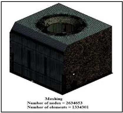
In order to ensure that the modal and harmonic results are realistic and appropriate, the model of the OCB has been validated. The optimum size of the mesh is selected for obtaining the accurate results in the least computational time for the available computer hardware. In this paper, the OCB casing design has been optimized in terms of weight and vibration by 600 kg and 40 microns respectively to meet the Indian Railway standards. As per the data provided by the organization, it has been found that the OCB usually works at 2920 rpm and 0-50 Hz frequency range. The existing OCB model was tested for mode shapes generated between the frequencies range i.e. 0-50 Hz, and it has been observed that the mode shape values comes under this range increases the effect of resonance. An unwanted stiffeners have been removed from the assembly to reduce the weight of the OCB casing. Thus, mode shapes deformations were studied and stiffeners of desired size and thickness were then added at the required positions. Grids of different types were further generated and solved for modal and harmonic analysis of optimized design followed by meshing the components of OCB using two different meshes having element size of 7 mm. Hex dominant mesh was applied on the casing for obtaining the precise results since hex dominant (or quad) meshes generally work better for wall-bounded flows so orthogonal grids can be maintained in the wall-normal direction as shown in Fig. 3(a). Tetrahedron mesh was implemented on the blades due to its byzantine shape as shown in Fig. 3(b).
(a) (b)
Fig. 3. Meshing of the OCB assembly:
(a) Hex Dominant mesh on casing (b) Tetrahedron mesh on impeller.
During the meshing of OCB assembly with mesh size 7 mm, the number of nodes and elements produced on the assembly are
2634653 and 1334301 respectively. To finalize the design, OCB prototypes were prepared and then tested to measure the vibration value using vibration meter.
5 RESULTS&DISCUSSIONS
The OCB assembly with the existing & modified design was analyzed for modal and harmonic analysis. The weight of the existing assembly was 639.03kg which was also high and does not meet the Railway standard (i.e. 600kg) and cause of rejection of the product. The modal analysis of existing model has been performed in the frequency range of 0-50 Hz using ANSYS software and has been found that there are 8 mode shapes in this frequency range. The results obtained by modal analysis for existing OCB assembly are shown in Table 2.
TABLE 2
MODAL ANALYSIS RESULTS FOR EXISTING OCB ASSEMBLY FREQUENCY
(HZ) 1.84 10.69 20.66 26.41 27.94 30.89 44.65 47.51 DEFORMATIO
N (MM) 8.08 1.82 3.61 16.50 17.14 19.81 19.99 2.34
Also, these 8 critical frequencies for existing OCB assembly increase the resonance effect and alters the deformation value at all frequencies. The variation of mode shape deformation with modal frequencies graph is shown in Fig. 4.
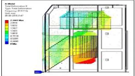
Fig. 4. Modal analysis deformation results for existing OCB
For modal analysis, within the frequency range of 0-50 Hz, the maximum value of deformation was found to be 19.99 mm at 44.65 Hz, whereas the deformation of 2.34 mm takes place on the left face of the assembly at 47.51 Hz. The deformation results of mode shapes at frequency 47.51 Hz are shown in Fig. 5. The flow lines with different colours describe the direction of deformation. Also, the red lines indicate the maximum effect of vibration at the bottom of the motor.
3490
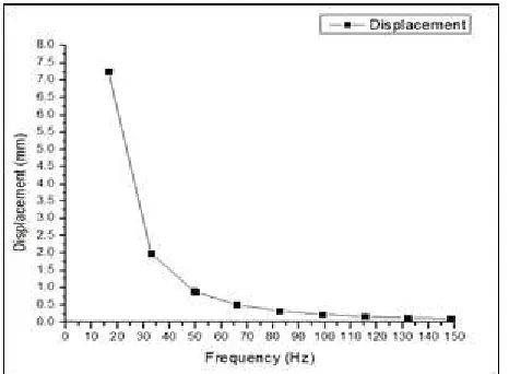
The existing OCB assembly has been further tested for harmonic response with mesh size of 7 mm and measured the vibration amplitude in terms of displacement at 50 Hz. Table 3 shows the harmonic analysis results obtained for existing cooling blower assembly. A significant decrease in displacement values has been observed with the increase in harmonic frequencies.
TABLE 3
HARMONIC ANALYSIS RESULTS FOR EXISTING OCB ASSEMBLY
FREQUENCY
(HZ) 16.5 33 49.5 50 66 82.5 99 115.5 DISPLACEMENT
(MM) 7.25 1.98 0.9 0.88 0.51 0.33 0.23 0.17
The maximum amplitude of the vibration was noticed to be 7.25 mm at 16.5 Hz. The variation of vibration amplitude, in terms of displacement, with harmonic frequencies is shown in Fig. 6.
Fig. 6. Variation of vibration amplitude for existing OCB
The effect of vibration on casing of oil cooling blower at 50 Hz is shown in Fig. 7. From the harmonic response analysis, it has been noticed that the maximum value of amplitude in terms of displacement is 0.88 mm (i.e. 880 µm), which seems very high by taking into account the Indian railway standards i.e. 40 µm.
Fig. 7. Effect of vibration on existing OCB assembly at 50 Hz
Hence, the OCB assembly was modified to meet the weight criterion of Indian railways. The weight of the updated model was reduced to 591.62 kg by removing the extra stiffeners to achieve the criteria. The location of the stiffeners was further
optimized to reduce the vibrations produced during operations in the OCB assembly. The results obtained for modified design of OCB casing using modal analysis are depicted in Table 4.
TABLE 4
MODAL ANALYSIS RESULTS FOR MODIFIED OCB ASSEMBLY
FREQUENCY
(HZ) 1.32 54.67 57.76 73.36 75.85 90.37 97.41 103.5 DEFORMATIO
N (MM) 8.02 10.27 10.96 5.41 7.27 7.02 6.75 2.89
The results obtained for modal analysis of modified OCB assembly have been found better as compared to existing OCB design. In addition, only single mode shape at 1.324 Hz has been found within the frequency ranges 0-50 Hz, followed by the next value of mode shape at 54.67 Hz. The variation of mode shape deformation with modal frequencies graph is shown in Fig. 8.
Fig. 8. Modal analysis deformation results for modified OCB
It can be noticed that the values of deformation at 1.32 Hz, 54.67 Hz are 8.02 mm and 10.27 mm respectively. The effect of deformation at 54.67 Hz was observed on the impeller assembly as shown in Fig. 9. The deformation takes place is indicated by flow lines, and ‘red’ lines shows the area where maximum deformation occurs.
Fig. 9. Deformation of modified OCB at 54.67 Hz
3491
analysis results obtained for modified cooling blower assembly.
TABLE 5
HARMONIC ANALYSIS RESULTS FOR MODIFIED OCB ASSEMBLY FREQUENCY
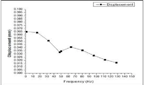
(HZ) 1 16 32 48 50 64 80 96 DISPLACEMEN
T (MM) 0.065 0.063 0.051 0.032 0.034 0.04 0.035 0.02
7
It has been found that for frequency ranges 0-50 Hz, the vibration amplitude decreases from maximum value 0.065 mm to 0.034 mm at 1 Hz and 50 Hz respectively. The variation of vibration amplitude with harmonic frequencies is shown in Fig. 10.
Fig. 10. Variation of vibration amplitude for modified OCB
The influence of vibration on OCB casing at 50 Hz has been shown in Fig. 11. The maximum value of vibration amplitude in terms of displacement has been found to be 0.0346 mm i.e. 34.6 µm, which is acceptable as per the Indian railway standards.
(a)
(b)
Fig. 11. Effect of vibration on OCB assembly at 50 Hz. (a) Top view of the OCB (b) Side view of the OCB.
A sample cooling unit established on the optimal design was manufactured, fabricated and verified by the company. An excellent performance of the sample production of oil cooling blower has proved the effectiveness of the proposed design.
6 CONCLUSION
The design and locations of the stiffeners has been optimized to reduce weight and vibrations in a centrifugal oil cooling blower. The modal and harmonic analysis was carried out to optimize the design and location of stiffeners, and to determine the vibration amplitude respectively. Then, after finalization of design and analysis as per Indian railways standards, the sample assembly was tested on the test rig. The major findings that were observed in this study are as follows: a) The weight of the OCB casing was reduced by removing
the unwanted stiffeners. The location of the stiffeners was further optimized to reduce the vibrations produced during operations in the OCB assembly.
b) The weight of modified OCB assembly has been reduced to 591.62 kg from 639.03 kg of existing OCB assembly. c) The modified model has only single mode shape having
deformation value of 8.02 mm at frequency 1.32 Hz, whereas there were 8 mode shapes in case of existing at same frequency range.
d) The amplitude of the vibration amplitude was found to be 50 Hz is 0.034 mm i.e. 34µm which is acceptable as per the Indian railway standards i.e. 40µm
Findings from present simulations can be used for better design of OCB assembly casing and impeller made of different material or applying computational fluid dynamics (CFD) analysis.
ACKNOWLEDGMENT
The authors acknowledge the company M/s P.D. Steels Pvt. Ltd. Mohali, India, for providing us the opportunity for this work.
REFERENCES
[1] Huang, C. H., & Hung, M. H. (2013). An optimal design algorithm for centrifugal fans: Theoretical and experimental studies. Journal of Mechanical Science and Technology, 27(3), 761-773.
3492
monitoring: a review. Archives of Computational Methods in Engineering, 23(4), 585-594.
[3] Cai, J. C., Qi, D. T., & Lu, F. A. (2009). Numerical studies on fan casing vibration and noise radiation. In ASME Turbo Expo 2009: Power for Land, Sea, and Air, American Society of Mechanical Engineers, pp. 255-264.
[4] Krishna, S. R., Krishna, A. R., & Ramji, K. (2011). Reduction of motor fan noise using CFD and CAA simulations. Applied acoustics, 72(12), 982-992.
[5] Huang, C. H., & Tseng, W. C. (2016). An optimal volute spiral case design for centrifugal fan: theoretical and experimental studies. International Journal of Mechanics and Materials in Design, 12(2), 223-240.
[6] Baloni, B. D., Pathak, Y., & Channiwala, S. A. (2015). Centrifugal blower volute optimization based on Taguchi method. Computers & Fluids, 112, 72-78.
[7] Yu, Z., Li, S., He, W., Wang, W., Huang, D., & Zhu, Z. (2005). Numerical simulation of flow field for a whole centrifugal fan and analysis of the effects of blade inlet angle and impeller gap. HVAC&R Research, 11(2), 263-283.
[8] Huang, C. K., & Hsieh, M. E. (2009). Performance analysis and optimized design of backward-curved airfoil centrifugal blowers. HVAC&R Research, 15(3), 461-488.
[9] Wu, H., Zhou, Q., Zhang, Z., & An, Q. (2012). Vibration analysis on the rolling element bearing-rotor system of an air blower. Journal of mechanical science and technology, 26(3), 653-659.
[10] Mittal, A., Gandhi, B. K., & Singh, K. M. (2009). Improvement in the design of a centrifugal impeller for an oil cooling blower system using computational fluid dynamics. Proceedings of the Institution of Mechanical Engineers, Part A: Journal of Power and Energy, 223(8), 981–989.
[11] https://rdso.indianrailways.gov.in/works/uploads/File/RDSO%2 0spec%20no_0123%20.pdf
[12]
http://www-eng.lbl.gov/~als/FEA/ANSYS_V9_INFO/Workbench Simulation_9.0_Intro_3rd_Edition/ppt/AWS90_Ch10_Harmoni c.ppt