ISSN (Print) : 2320 – 3765 ISSN (Online): 2278 – 8875
I
nternational
J
ournal of
A
dvanced
R
esearch in
E
lectrical,
E
lectronics and
I
nstrumentation
E
ngineering
(A High Impact Factor, Monthly, Peer Reviewed Journal)
Website: www.ijareeie.com
Vol. 7, Issue 5, May 2018
MPPT of PV Array Using Fuzzy Logic
Controller Based LUO Converter
Angala Vaishnavi.S1, Anusha.M2, Barath.M.S3, Janani.R4
Assistant Professor, Dept. of EEE, Sri Venkateswara College of Engineering, Chennai, India1
UG Student, Dept. of EEE, Sri Venkateswara College of Engineering, Chennai, India2
UG Student, Dept. of EEE, Sri Venkateswara College of Engineering, Chennai, India3
UG Student, Dept. of EEE, Sri Venkateswara College of Engineering, Chennai, India4
ABSTRACT: The solar power extracted using a solar array varies mainly depending on the weather conditions. Thus, many new algorithms have been projected to track the maximum power point (MPP) of the solar PV system. This paper, presents a comparative study between two of the most intelligent control methods used in order to optimize the efficiency of the solar PV system, the Incremental conductance algorithm and fuzzy logic controller algorithm applied to a Luo converter. The Luo converter increases the output voltage depending on the duty cycle of switching device .The proposed controller adjusts the duty cycle of the Luo converter switch to track the maximum power out of the solar PV array. Finally the performance comparison is done between Incremental conductance and Fuzzy logic controller method, in which Fuzzy logic controller method has the merit of improved efficiency. Both these controller has been simulated using MATLAB version (R2015a).
KEYWORDS: Solar PV array; Maximum Power Point; Incremental conductance algorithm; fuzzy logic controller algorithm; Luo converter.
I. INTRODUCTION
ISSN (Print) : 2320 – 3765 ISSN (Online): 2278 – 8875
I
nternational
J
ournal of
A
dvanced
R
esearch in
E
lectrical,
E
lectronics and
I
nstrumentation
E
ngineering
(A High Impact Factor, Monthly, Peer Reviewed Journal)
Website: www.ijareeie.com
Vol. 7, Issue 5, May 2018
algorithms, there by comparing and studying the effectiveness of these algorithms in tracking and obtaining the maximum power point [3]. The comparative simulation study of two important MPPT algorithms specifically perturb and observe and incremental conductance is performed as these are used widely because of its low-cost and ease of realization. Some important parameters such as voltage, current and power output for each different combination have been traced for both algorithms. Sepic have a pulsating output current and it requires current handling capability, in order to overcome these drawbacks the Luo converter is used, as it has the ability to reduce ripple voltage and current levels without inverting the polarities. The converters with incremental conductance can track the maximum power with reduc0ed oscillations [4]. Maximum Power Point Tracking (MPPT) for photovoltaic using incremental conductance method is studied and is applied with various converters and the efficiency of operation of these converters are compared [5]. The incremental conductance MPPT algorithm based on solar photovoltaic system using a CUK converter is designed and simulated and is studied in comparison with other converter topologies and the effectiveness of these converters is determined [6]. Performance enhancement of PV system using Lou converter and improved Lou converter modifications with increasing voltage ratio. The positive output super-lift Luo converter that allows significant increase the voltage transfer gain by the modest means. In the simplest case this increase is provided by replacing the inductor by the switched-inductor structure consisting of two inductors and three diodes. This allows getting practically double increase in the line-to-output voltage ratio at the high values of duty cycle. The study indicates possible ways to further increase the output voltage ratio without additional switches - by the use of magnetically coupled inductors and diode-capacitor voltage multipliers [7],[8]. Simulation of fuzzy logic control based MPPT technique for photovoltaic system is studied and the results are compared with results using incremental conductance method and their efficiency is studied [9]. By applying all these techniques a comparative study is conducted and the overall operating efficiency of various technique is obtained.
II.SYSTEM MODEL
The efficiency of a solar cell is very low. In order to increase the efficiency, different methods are to be undertaken to match the source and load properly. One such method is the Maximum Power Point Tracking (MPPT).This is a technique used to obtain the maximum possible power from a varying source. In photovoltaic systems the I-V curve is Non-linear, thereby making it difficult to be used to power a certain load. This is done by utilizing a boost converter whose duty cycle is varied by using a MPPT algorithm.
Fig 1: Block diagram of the proposed system.
MPPT CONTROLLER: MPPT algorithms are used by the converters to match the impedance of the load and the out impedance of the solar cell system. Thus the power delivered will be maximum, which defines the peak power point. This can be achieved by placing a boost converter in between the solar and the load. Hence the net impedance viewed by the solar cellischangedbychanging the duty cycle of the boost converter. A MPPT algorithm is implemented to change the duty cycle of the boost converter thereby forcing the solar cell to operate in its Maximum Power Point
ISSN (Print) : 2320 – 3765 ISSN (Online): 2278 – 8875
I
nternational
J
ournal of
A
dvanced
R
esearch in
E
lectrical,
E
lectronics and
I
nstrumentation
E
ngineering
(A High Impact Factor, Monthly, Peer Reviewed Journal)
Website: www.ijareeie.com
Vol. 7, Issue 5, May 2018
incrementing/decrementing until MPP is reached. Therefore, the maximum power point is achieved when the incremental conductance is equal to the negative of the instantaneous conductance.
Fig.2: Flow chart of incremental conductance method
Fuzzy logic control:The basic concept understanding fuzzy logic is that of a linguistic variable, that is a variable whose values are words rather than number. Fuzzy logic uses fuzzy sets to related classes of objects with unclearly defined boundaries in which membership is a matter of degree. The fuzzy logic system is more flexible than classical and conventional method. Fuzzy logic controller works with imprecise inputs, it does not need an accurate mathematical model
Fig.3: Components of fuzzy logic based MPPT
The fuzzy controller consists of four functional blocks, fuzzification, fuzzy rule, an inference Engine and the defuzzification. The fuzzy controller design contains the three following steps:
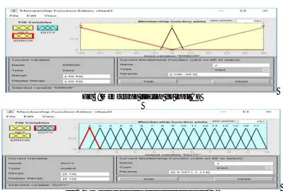
Fuzzification:In this process of fuzzification, converting the systems actual input value E and CE into linguistic fuzzy labels using fuzzy membership function. In fuzzification fuzzy logic collects the raw data from system and it converts crisp inputs into fuzzy inputs. Here fuzzy inputs are error (E) and change in error (CE), which are based on the laws of MPPT.
ISSN (Print) : 2320 – 3765 ISSN (Online): 2278 – 8875
I
nternational
J
ournal of
A
dvanced
R
esearch in
E
lectrical,
E
lectronics and
I
nstrumentation
E
ngineering
(A High Impact Factor, Monthly, Peer Reviewed Journal)
Website: www.ijareeie.com
Vol. 7, Issue 5, May 2018
Fig 5: Membership function for input CE
Fig 6:Membership function for output duty cycle (D)
Table.1: Fuzzy logic rule table
1 if (set is 1) And (Error is z) then (Duty is 1)
2 if (set is 1) And (Error is p) then (Duty is 2)
3 if (set is 1) And (Error is n) then (Duty is 2)
4 if (set is 2) And (Error is p) then (Duty is 3)
5 if (set is 2) And (Error is n) then (Duty is 1)
6 if (set is 2) And (Error is z) then (Duty is 3)
7 if (set is 3) And (Error is p) then (Duty is 4)
8 if (set is 3) And (Error is n) then (Duty is 2)
9 if (set is 3) And (Error is z) then (Duty is 4)
10 if (set is 4) And (Error is p) then (Duty is 5)
11 if (set is 4) And (Error is n) then (Duty is 3)
12 if (set is 4) And (Error is z) then (Duty is 5)
13 if (set is 5) And (Error is p) then (Duty is 6)
14 if (set is 5) And (Error is n) then (Duty is 4)
15 if (set is 5) And (Error is z) then (Duty is 6)
16 if (set is 6) And (Error is p) then (Duty is 7)
17 if (set is 6) And (Error is n) then (Duty is 5)
18 if (set is 6) And (Error is z) then (Duty is 7)
19 if (set is 7) And (Error is p) then (Duty is 8)
20 if (set is 7) And (Error is n) then (Duty is 6)
21 if (set is 7) And (Error is z) then (Duty is 7)
22 if (set is 8) And (Error is p) then (Duty is 9)
23 if (set is 8) And (Error is n) then (Duty is 7)
ISSN (Print) : 2320 – 3765 ISSN (Online): 2278 – 8875
I
nternational
J
ournal of
A
dvanced
R
esearch in
E
lectrical,
E
lectronics and
I
nstrumentation
E
ngineering
(A High Impact Factor, Monthly, Peer Reviewed Journal)
Website: www.ijareeie.com
Vol. 7, Issue 5, May 2018
25 if (set is 9) And (Error is p) then (Duty is 10)
26 if (set is 9) And (Error is n) then (Duty is 8)
27 if (set is 9) And (Error is z) then (Duty is 10)
28 if (set is 10) And (Error is p) then (Duty is 11)
29 if (set is 10) And (Error is n) then (Duty is 9)
30 if (set is 10) And (Error is z) then (Duty is 11)
31 if (set is 11) And (Error is p) then (Duty is 10)
32 if (set is 11) And (Error is n) then (Duty is 12)
33 if (set is 11) And (Error is z) then (Duty is 12)
34 if (set is 12) And (Error is p) then (Duty is 13)
35 if (set is 12) And (Error is n) then (Duty is 11)
36 if (set is 12) And (Error is z) then (Duty is 13)
37 if (set is 13) And (Error is p) then (Duty is 14)
38 if (set is 13) And (Error is n) then (Duty is 12)
39 if (set is 13) And (Error is z) then (Duty is 14)
40 if (set is 14) And (Error is p) then (Duty is 15)
41 if (set is 14) And (Error is n) then (Duty is 13)
42 if (set is 14) And (Error is z) then (Duty is 15)
43 if (set is 15) And (Error is p) then (Duty is 16)
44 if (set is 15) And (Error is n) then (Duty is 14)
45 if (set is 15) And (Error is z) then (Duty is 16)
46 if (set is 16) And (Error is p) then (Duty is 17)
47 if (set is 16) And (Error is n) then (Duty is 15)
48 if (set is 16) And (Error is z) then (Duty is 17)
49 if (set is 17) And (Error is p) then (Duty is 17)
50 if (set is 17) And (Error is n) then (Duty is 15)
51 if (set is 17) And (Error is z) then (Duty is 17)
Defuzzification:Fuzzy rule based systems evaluate linguistic if-then rules using fuzzification, inference and transform the fuzzy results in to crisp, defuzzification is performed. Defuzzification is the process of converting a fuzzified output into a single crisp value with respect to a fuzzy set. The defuzzified value in FLC (Fuzzy Logic Controller) represents the action to be taken in controlling the process.
LUO CONVERTERS: Luo converters are the simplest form of DC-DC converter which operates on voltage lift technique. This Luo converter operates on PUSH-PULL state. The switched type Luo converter is developed. Switched capacitor DC-DC converters are made only of switched capacitors. Because switchedcapacitorscanbe integrated into power semiconductor integrated circuit (IC) chips, they have limited size and work at high switching frequency. The elementary LUO converter performs buck or boost operation in DC to DC conversion.
ISSN (Print) : 2320 – 3765 ISSN (Online): 2278 – 8875
I
nternational
J
ournal of
A
dvanced
R
esearch in
E
lectrical,
E
lectronics and
I
nstrumentation
E
ngineering
(A High Impact Factor, Monthly, Peer Reviewed Journal)
Website: www.ijareeie.com
Vol. 7, Issue 5, May 2018
Fig.9: Luo converter when the switch is in OFF condition
III.SIMULATION OF LUO CONVERTER WITH INC AND FUZZY LOGIC CONTROLLER
The simulation is done using MATLAB version R2015a.The model is built using a solar panel with the luo converter and the maximum power point tracking device mainly.The figures below are the devices used to build the model in the MATLAB.
Fig.10: MPPT controller
Fig.11:Detailed structure of MPPT controller
Fig.12:Diagram of the Luo converter Fig.13: Diagram of fuzzy logic controller
ISSN (Print) : 2320 – 3765 ISSN (Online): 2278 – 8875
I
nternational
J
ournal of
A
dvanced
R
esearch in
E
lectrical,
E
lectronics and
I
nstrumentation
E
ngineering
(A High Impact Factor, Monthly, Peer Reviewed Journal)
Website: www.ijareeie.com
Vol. 7, Issue 5, May 2018
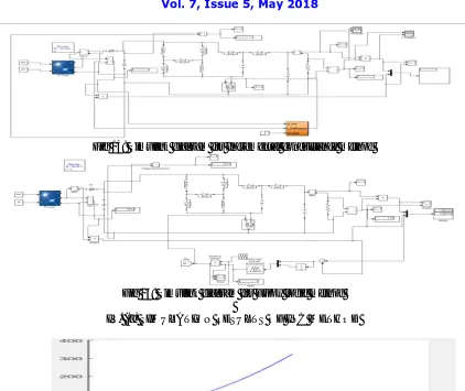
Fig 14: Simulink diagram for Incremental conductance method
Fig 15: Simulink diagram for Fuzzy logic method
IV. (a) SIMULATION RESULTS OF INC METHOD
Fig. 16: Output curve between the Power (y-axis) and voltage (x-axis) of INC method.
ISSN (Print) : 2320 – 3765 ISSN (Online): 2278 – 8875
I
nternational
J
ournal of
A
dvanced
R
esearch in
E
lectrical,
E
lectronics and
I
nstrumentation
E
ngineering
(A High Impact Factor, Monthly, Peer Reviewed Journal)
Website: www.ijareeie.com
Vol. 7, Issue 5, May 2018
Fig.18: Simulation Output- Power waveform of INC method
(b) SIMULATION RESULTS OF FUZZY LOGIC METHOD
Fig.19: Output curve between Power (y-axis) and voltage (x-axis) of fuzzy logic control method
Fig.20: Output curve between current (y-axis) and voltage (x-axis) of Fuzzy logic control method
Fig.21: Simulation Output –Power waveform of Fuzzy logic method
ISSN (Print) : 2320 – 3765 ISSN (Online): 2278 – 8875
I
nternational
J
ournal of
A
dvanced
R
esearch in
E
lectrical,
E
lectronics and
I
nstrumentation
E
ngineering
(A High Impact Factor, Monthly, Peer Reviewed Journal)
Website: www.ijareeie.com
Vol. 7, Issue 5, May 2018
Table.3: Comparison based on simulation output
INC Method Fuzzy Logic
Input voltage: 66.43 V Input voltage : 67.54 V
Output voltage: 178.3 V Output voltage: 223.6 V
Output current:2.1A Output current: 2.3 A
Source power : 781.7 W Source power:643.9 W
Load end power: 318 W Load end power:500.1
V.CONCLUSION AND FUTURE SCOPE
Photovoltaic model using MATLAB/SIMULINK and design of appropriate Luo converter with a maximum power point tracking facility are presented here. A new method for MPPT based fuzzy logic controller is presented and compared with the conventional INC MPPT method. The model is tested under disturbance in both solar radiation and photovoltaic temperature. Simulation results shows that theproposedmethodeffectivelytracks the maximum power point . The oscillation around MPP is decreased and the response is faster in compared with the conventional methods. Comparingthetrackingefficiencyofbothmethods,itindicatesthatthe proposed method has a higher efficiency than the conventionalINCMPPTmethod.Infuture, Fuzzy logic method, different defuzzification methods can be implemented and further improvements could be implemented.
REFERENCES
[1] Bialasiewicz J.T, (July) (2008), ‘Renewable energy system with photovoltaic power generators: operation and modelling, in ‘IEEE Trans. Industrial, Electron. pp. 2752–2758.
[2] JainS, Agarwal V (2004),’A new algorithm for rapid tracking of approximate maximum power point in photovoltaic systems’, in‘IEEE Power Electronics’, Lett.2, pp. 16–19.
[3] Villalva M, Gazoli J, Filho E.R (2009), ‘Comprehensive approach to modelling and simulation of photovoltaic arrays”, IEEE Trans. Power Electron. 24 pp.1198–1208.
[4] S. Nimimol, DR.V. Gopalakrishnan, Immanuel John Samuel (2015), ‘Comparative Analysis of Sepic and Luo converter with MPPT algorithms’, ISSN: 6736, Volume-03, ISSUE-02.
[5] RatnaIkaPutri, SaptoWibowo, MuhamadRifa(2014) ‘Maximum power point tracking for photovoltaic using incremental conductance method’ energy Procardia 68(2015)22-30.
[6] RanjivRoshan,YatendraYadav,UmashankarS,Vijayakumar D (2013) ‘Modelling and simulation of Incremental Conductance MPPT Algorithm Based Solar Photovoltaic System using CUK Converter’ in IEEE 978-1-4673-6150-7.
[7] D. Vanitha and G. Jayanthi(2016),’ Performance Enhancement of PV System using Luo converter and FLC based P&O MPPT’,ISSN 1990-9233, pp. 216-220,2016.
[8] YefimBerkovich, Boris Aerold, RotemMadar, AvrahamTwina(2015),‘Improved Luo converter modifications with increasing voltageratio’, in ‘IET Power Electronics ’, Vol.8, ISS. 2, pp. 202-212.