Approaches to Limit the Effect of Capacitor
Banks Switching Transients in Power Systems
Rahul Deshmukh*1, Prof. V.R. Aranke#2
PG Student, MCOE & RC, Nashik, Savitribai Phule Pune University, Pune, Maharashtra, India*1
Assistant Professor, MCOE & RC, Nashik, Savitribai Phule Pune University, Pune, Maharashtra, India#2
ABSTRACT: This study provides an introduction to capacitor bank switching transients, illustrates the effects of the capacitor banks switching in the utility primary distribution system at different places of the power system, but especially at the customer’s plant. Study covers different operational cases to find the suitable method or techniques can be used to limit the effect of capacitor switching transients.
Transient disturbances in power systems may damage key equipment, potentially having a great impact on system reliability. These transients may be introduced during normal switching operations, lightning strikes, or because the equipment failure. Therefore, time-domain computer simulations are developed to study dangers cases due to transient occurrences.
KEYWORDS: Capacitor banks; Transient overvoltage and current; Energisation inrush; Back-to-back switching; Pre-insertion resistor and inductor
I. INTRODUCTION
Capacitor bank energizing transients are becoming increasingly more important with the growing number of capacitor bank installations in power systems. This is because capacitor bank switching is one of the most frequent utility operations, potentially occurring multiple times per day and hundreds of time per year throughout the system, depending on the need for system voltage / VAR support from the banks. There are a number of important concerns when capacitor banks are applied at the transmission system voltage level. Transient related currents and voltages appearing on a power system associated with utility capacitor bank installations include voltage transients at the capacitor bank substation and neighbouring substations (include phase-to- ground or phase-to- phase over voltages), power quality impact on sensitive customer loads due to variations in voltage, capacitor bank Energisation inrush currents and capacitor bank outrush currents due to faults in the vicinity of capacitor banks.
Utilities normally apply capacitors on three-phase sections. Applications on single-phase lines are done but less common. Application of three-phase banks downstream of single-phase protectors is normally not done because of ferroresonance concerns. Most three-phase banks are connected grounded-star on four-wire multi-grounded circuits. Some are connected in floating star connected. On three-wire circuits, banks are normally connected as a floating star. Double-star connected banks and multiple series groups are used when a capacitor bank becomes too large for the 3100 KVAR per group for the expulsion type of fuses.
Capacitor dielectrics must withstand high voltage stresses during normal operation, on the order of 78 kV/ mm, and no other medium-voltage equipment has such high voltage stress. Capacitors are designed to withstand over-voltages for short periods of time. New capacitors are tested with at least a 10 sec overvoltage, either a dc-test voltage of 4.3 times rated RMS or an ac voltage of twice the rated RMS voltage (IEEE Std. 18-2002).
Capacitors must have an internal resistor that discharges a capacitor to 50 V or less within 5 min when the capacitor is charged to the peak of its rated voltage √2Vrms. This resistor is the major component of losses within a capacitor. The resistor must be low enough such that the RC time constant causes it to decay in 300 sec as:
50
√2V ≤ e
Where
V- Capacitor voltage rating, V R- Discharge resistance, Ω C- Capacitance, F
IEEE guides suggest selecting a fuse capable of handling 1.25 to 1.35 times the nominal capacitor current (IEEE Std. C37.48-1997), a 1.35 factor is most common. Capacitors are rated to withstand 180% of rated RMS current, including fundamental and harmonic currents. Fusing is normally not based on this limit, and is normally much tighter than this, usually from 125 to 165% of rated RMS current. Occasionally, fuses in excess of 180% are used. In severe harmonic environments, normally fuses blow before capacitors fail, but sometimes capacitors fail before the fuse operates. This depends on the fusing strategy. The smallest size fuse that can be used is:
Imin= .
. Where
Imin - minimum fuse rating, A I1 - capacitor bank current, A
II. FACTORS AFFECTING DUE TO SWITCHING TRANSIENTS
A. Capacitor Bank
Capacitor banks are installed near to the load centre will reduce the magnitude of the reactive power drawn by the load from the utility distribution system. The most common method today for improving power factor is the installation of the capacitor bank. These bank are very economical and these installations reduces the magnitude of reactive power supplied to the load. Therefore supply of reactive power from utility power system is now reduced.
B. Capacitor size and location
Generally capacitors are rated in ‘VAR’ which indicates the quantity of reactive is supplied by the capacitor. If the system draws 310KVR for every hour of the day. A fixed capacitor of 310KVR canbe installed to provide the required reactive energy by the system. Switched capacitors are not connected all the time, it gives flexibility in the control of power factor correction, losses and system voltage because they may get switched on and off all the time. It depends on the control quantity, Voltage:-Control or improvement of voltage regulation. Current: - Current Magnitude Tie switch: - VAR has a high degree of regularity with respect to time. Reactive current control: - VAR demand.
Usually, the capacitor banks are placed at the location of minimum power factor by measuring the voltage, current, KW, KVAR, and kVA on the feeder to determine the maximum and minimum load conditions. Many utilities prefer a power factor of 0.95. The peaks and valleys in the KVAR demand curve make it difficult to use a single fixed capacitor bank to correct the power factor to the desired level.
C. Power Frequency Over voltages in Power Systems
The power frequency over voltages occurs in large power systems and they are of much concern in EHV systems, i.e. systems of 400 kV and above. The main causes for power frequency and its harmonic over voltages are,
(a)Sudden damage to the loads,
(b)Interruption of inductive loads or connection of capacitive loads, (c)Ferranti effect, unsymmetrical faults
(d)Overload in transformers, etc.
D. Control of Over-voltages due to Switching
The over voltages due to switching and power frequency may be controlled by
b)Phase controlled closing of circuit breakers, c)Drainage of trapped charges before reclosing, d) Use of shunt reactors
e) Limiting switching surges by suitable surge arresters
E. Control Switching on circuit breaker
Sequence of events for controlled switching in this example is as follows; a)Circuit breaker close request is received at point 1
b)In order to determine the target point, next voltage zero is detected at point 2
c)Knowing the circuit breaker closing time and power system frequency, target voltage zero is identified d)Time to give close command to the circuit breaker is estimated, and the close command is applied at point 3 e)Contacts of the circuit breaker touches at target voltage zero at point 4
Fig- 1 Switching Phenomenon
F. Power Quality Problem
The quality of electric power has been a constant topic of study, mainly because poor power quality can lead to economic losses, especially in industrial processes, due to loss production. Due to growing connections of power electronics based equipment. One of the more common power quality problems for consumers are transient voltages in the system. That result from capacitor bank switching and, to a lesser extent, harmonic distortion once the capacitor is energized. The energizing transient, a power quality issue, is important because it is one of the most frequent system switching operations.
G. Transient Recovery Voltage
Circuit breakers provide the mechanism to interrupt the short-circuit current during a system fault. When the breaker contacts open, the fault current is not interrupted instantaneously. Instead, an electric arc forms between the breaker contacts, which is maintained as long as there is enough current flowing. Since the fault current varies sinusoid ally at the power frequency, the arc will extinguish at the first current zero. However, at the location of the arc, there are still hot, ionized gases and, if voltages exceeding the dielectric capability of the contact gap develop across the open contacts of the circuit breaker, it is possible that the arc will reignite.
III. CAPACITOR ENERGISATION
During the switching of shunt capacitor banks, high magnitude and high frequency transients can occur. The transient is characterized by a surge of current having a high magnitude and a frequency as high as several hundred Hertz. There is also a transient overvoltage on the bus, caused by the surge of inrush current coming from the system source.
Fig 2- Capacitor Energisation
Basics concepts concern to capacitor energisation are explained in Figure 1, where resistances were neglected for simplification. When the first capacitor C1 is energized (closing S1) the current and voltage in the capacitor are given by equations 3 and 4.
VC1(t)=V-[V-VC1(0)]sinω1t
It = sin ωt
IV. TECHNIQUES OF REDUCTION OF CAPACITIVE SWITCHING TRANSIENTS
There are many technologies and methods are available to mitigate transients such as a use of pre-insertion of the resistor, surge arrestor connected across the capacitor bank, and current limiting resistor. Each type of switching transients represents different simulation [10].
A. Current Limiting Reactor
In this technique, the suitable rating of a current limiting resistor is used in series with the capacitor bank. Due to this reactor surge impedance of the circuit get increased and hence peak inrush current get decreased. As the function of the inductor is opposing the change in current so that current cannot change instantly. Therefore increased frequency components of transients are restricted and the effect of this inrush transients current is compressed. .It is clear that as The Current increases in the negative half cycle and this can be attributed exchange of energy between two energy storing devices such as inductor and capacitor. The purpose of X/R ratio is for the sharpness of tuning, also for damping purposes, X/R ratio is lower [10]. Here reactor of particular rating is used in series with the capacitor bank. Due to use of this reactor the surge impedance of the circuit increases and hence the peak of inrush current cannot change instantly. Therefore higher frequency components of transients are constrained and the effect of these inrush current is compressed.
B. Switching or pre-insertion of resistor
C. By using Surge arrester
Another technique to reduce the current transients, the gap type of surge arrester are connected in the series nonlinear resistor can be used along with capacitor bank to reduce higher extent transient stress. It is set in such a way to remain non-conducting at energizes the gap, the capacitor gets discharged and energy dissipated through the resistor. However, if gapless metal oxide is used when capacitor will not discharge below voltage.
The Metal Oxide surgearrester exhibits dynamic characteristics such that the voltage across the surge arrester increases as the time-to-crest of the arrester current decreases and the voltage of arrester reaches a peak before the arrester current
peaks [13].Theinstalled location and rating of surge arresters are provided. The maximum ratings, and in particular the
energy absorption capability will be determined with study and characteristic V-I of surge arresters.
V. SIMULATION SYSTEM AND TEST RESULTS
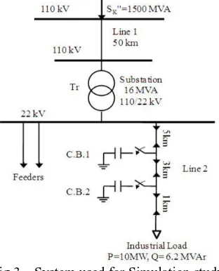
Simulation of shunt capacitors switching is studied in this paper. The network shown in Figure 2 was used for the purpose of this paper. The study focuses on the effects of the switching the capacitor banks in the utility primary distribution system, at the customer’s plant.
The network consists of one industry, which it’s main load basically contains induction motors about 10 kW of installed power, with a total rated power about 10 MW at 22 kV, cosφ =0.85 and the industry has power factor (P.F.) correction capacitors to correct from 0.85 to 0.95, according to their needs. The network is fed by a cable in grounded structure and along the feeder two capacitor banks (950 and 1400 kVAR) were installed to simulate a real life case.The switching process is done by two switches, installed at the external phases, with the internal phase permanently energized.
Fig 3 – System used for Simulation study
The substation transformer 110/22 kV is modelled as 3-phase, -Y, with ground Y and with the labels values as shown in Table 1 below.
Table 1 - Values of 110/22 kV Transformer Parameter Values
Power(MVA 16
The transmission line 1 is made of 240AlFe6, length 50km and was modelled by LCC Line/Cable procedure as an overhead line, 3-phase, type PI. Rho (ground resistivity) = 100 Ωm, Freq. initial frequency =50 Hz. All loads are modelled by the ATP model RLC3, where the values of the model are calculated by the equations, R=U2/P, L=(U2/Q)/2πf and C=0. The values are listed in the table 2 below.
Table 2- Parameters of the Loads Parameter Values
P(MW) 10
Q(MVAr) 6.197 cos φ 0.85
R 48.4 Ohm L 248.72 mH
The capacitor banks (950 and 1400 kVAr) are modelled by the ATP model RLCD3, where the value of one phase capacitor is calculated as C=Q/2πfU2 (C.B.1=6.25 µF and C.B.2=9.21 µF). The capacitor banks are in series with a 3-phase time controlled switch, and programmed to switch on and off at the desired time intervals, but the transients normally occur during the energisation of the capacitor banks.
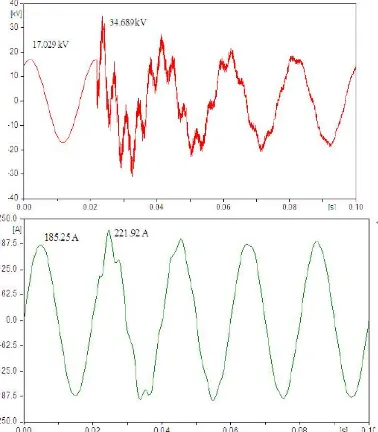
In this study the amplification of the transient overvoltage was experienced. The simulations can be realized for different situations, for example, when the industry’s load is modelled without, or with, the power factor correction capacitors, on the other hand the closing of the capacitors can be realized near the voltage peak or near zero crossing, with using pre-insertion resistors and inductors or without them. Generally, all simulations were done at the maximum load of the industry and for some different situations and the output data were taken just for A-phase.
Fig 5- . Inrush voltage and current, without P.F. capacitors, closing near zero crossing
The transient, in general, no higher than 2.0 p.u. on the primary distribution system, although ungrounded capacitor banks may yield somewhat higher values. Transient over-voltages on the end -user side may, under some conditions, reach as high as 3.0 to 4.0 p.u. on the low-voltage bus with potentially damaging consequences for all types of customer equipment. From the figures mentioned above it can be seen, that the transient represents a variation of a percentage in voltage or current for a fraction of a cycle, but that can have a damaging effect. The worst case situation was with switching occurring at the peak voltage.
A. Effect of Pre-insertion Resistors and Inductors
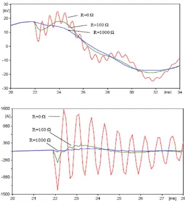
Preinsertion resistor is one of classical methods, which have been used for years by the electric utility industry for controlling capacitor-bank energisation overvoltages. The preinsertion is accomplished by the movable contacts sliding past the resistor contacts first before mating with the main contacts.
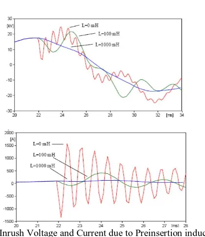
Fig 6- Inrush Voltage and Current due to Preinsertion inductor
Switches with preinsertion reactors have also been developed for this purpose. The inductor is helpful in limiting the higher-frequency components of the transient. In some designs, the reactors are intentionally built with high resistance so that they appear lossy to the energization transient, this damp out the transient quickly.
VI. CONCLUSION
Transients originating from utility capacitor bank switching was studied here. For realization various cases of sources of transient and to overcome it, a simple electric network representing a real life case was simulated.
The results shown in the figures gives a detailed perfect view about the effect of transients. Switching near the voltage peak magnifies transient voltages and currents, while switching near zero crossing reduces them. Depending on the industry power factor correction capacitors operation the transient voltages and currents can be amplified or mitigated. Finally, the use of resistors and inductors with the capacitors it can be seen that with the increase in size, but there is rapid reduction in the inrush current and voltage.
REFERENCES
1. Schultz, A. J., Johnson, I. B., & Schultz, N. R. (1959). Magnification of Switching Surges (V. 77, pp. 1418-1426). Trans. on Power Appar. and Syst.
2. Mikulec Milan, &HavličekVáclav (1999). ZákladyTeorieElektromagnetickýchObvodů 1 (pp. 159 161, 168-173), ČVUT. Czech Republic:
Prague.
3. GovindGopakumar, Huihua Yan, Dr. Bruce A. Mork, &Kalyan K. Mustaphi. Shunt Capacitor Bank SwitchingTransients: A Tutorial and Case Study.
4. R. SastryVedam, &Mulukutla S. Sarma (2009). PowerQuality-Var Compensation in Power Systems (pp: 215-240). Taylor & Francis Group. 5. Dugan, R. C., Granaghan, M.F Mc, Santoso, S. &Beaty, H.W. (2004). Electrical Power Systems Quality (pp: 140-144). New York:
McGraw-Hill
6. LászlóPrikler, & Hans Kristian Høidalen (2009). ATP-Draw Version5.6 for Windows,Users’ Manual. 7. T. A. Short, Electric Power Distribution Handbook. Boca Raton, FL:CRC Press, 2004, pp. 269–310. 8. T. M. Blooming, “Capacitor failure analysis,” IEEE Ind. Appl. Mag.,vol. 12, no. 5, pp. 38–48, Sep./Oct. 2006.
9. T. E. Grebe, “Application of distribution system capacitor banks and their impact on power quality,” IEEE Trans. Ind. Appl., vol. 32, no. 3, pp. 714–719, May/Jun. 1996.
10. Short, T. A. (2006). Electric Power Distribution -Equipment and Systems (pp: 269-295). Taylor & FrancisGroup, LLC.