Simulation Comparisons and Implementation of Wind Power Based
Induction Generator
G.Hymavathi
1, A.Rajamallaiah
2, Dr.KBVSR Subramanyam
3 1M.Tech Student, EEE, SR Engineering College, Warangal,Telangana 2Assistant Professor, Dept. of EEE, SR Engineering College, Warangal,Telangana 3Associate professor, Dept. of EEE, SR Engineering College, Warangal,TelanganaABSTRACT: This paper describes the performance
comparison of a wind power systems based on two differentinduction generators as well as the experimental demonstration of a wind turbine simulator for the maximumpower extraction. The two induction machines studied for the comparison are the squirrel-cage inductiongenerator (SCIG) and the doubly fed induction generator (DFIG). The techniques of direct grid integration, independent power control, and the droop phenomenon of distribution line are studied andcompared between the SCIG and DFIG systems. Both systems are modeled in Matlab/Simulink environment, and the operation is testedfor the wind turbine maximum power extraction algorithm results. Based on the
simulated wind turbine parameters, a
commercialinduction motor drive was programmed to emulate the wind turbine and is coupled to the
experimental generator systems. The
turbineexperimental results matched well with the theoretical turbine operation.
KEYWORDS: Doubly fed induction machines,
field-oriented control, maximum power tracking, and wind power system.
I. INTRODUCTION
With a lack of global concerns and fossil fuels for environmental sustainability, the need for renewable energy is actually increasing steadily. Wind energy conversion system is generally connected to the electric power grid andsupplies electric power to augment the starting power from some other generation systems by using nuclear energy or fossil fuel.The growing focus on renewable wind power has given rise to augmented interest on far more
dependable and beneficial electric generator systems. Induction generator devices have been commonly used as well as studied in windpower system due to their benefits over synchronous generators. Induction generator is actually a asynchronousgenerator, it's a kind of Ac electric generator. Induction generators work by mechanically switching their rotor fasteras opposed to the synchronous speed. These're helpful in uses like corner hydro power plants as well as wind turbines.
Induction generators are electrically and mechanically simpler compared to many other generator types. Induction generators areespecially appropriate for wind generating stations as in this particular case rate is surely a variable factor. Unlike synchronousmotors, induction generators are actually load dependent and can't be worn above for grid frequency management. Thesimple power conversion technique using squirrel cage induction generator (SCIG) is commonly recognized in fixed speed applications with less focus on the high effectiveness and balance of energy flow. Another main problemwith SCIG power system is actually the supply of reactive power. On the various other hand, the doubly given induction generator (DFIG)with variable speed ability has higher power capture efficiency and enhanced power quality. With the arrival of powerelectronic methods, a back-to-back converter, that is made up of 2 bidirectional converters as well as a dc link, functions as an optimum operation tracking interface between grid and generator.
produced power aren't controllable but just driven by the blowing wind speed. These typesof WECSs is able to bring down the energy variations as a result of the wind speed modifications, and it's also easy to achievemaximum power factors keeping track of (MPPT), because the back-to-back pulse width modulation (PWM) converter regulates the created energy. This paper proposes a setup of single outside feeding of DFIG (SEF DFIG) where arotor-side inverter. The energy consumed in the rotor side inverter is provided from the stator windings linked to thegrid. Since the SEF DFIG also can manage the torque, power, and pace of wind generator as in the traditional DFIGand work in variable speed mode and regulate the produced power in a variety of wind speed. The primary emphasis of thispaper is actually the modelling comparisons between the 3 induction generator wind power systems.
Fig. 1 shows the schematics of the SCIG system includingthe wind turbine, pitch control, and reactive powercompensator.The entire system includes three stages for delivering theenergy from wind turbine to the power grid.
Figure 1: SCIG wind power system topology
Since SCIG is of fixed-speed generator, for a particular wind speed, the output active power is fixed as
well. Thus, with the increase of wind speed, so does the output power until the nominal power is reached. Thewind speed at this moment is called nominal wind speed. Beyond this speed, the pitch angle
system will preventthe output power from exceeding the nominal value. That is, when the wind speed is below nominal value, thepower capture can vary with the change of wind speed; and when the wind speed is above nominal value, thepitch angle control system will limit the generated power by changing the pitch angle. In such way, the outputpower will be stabilized at nominal value where the wind speed is always above nominal speed. The pitch angleis determined by an open loop control of regulated output active power and by that shown in Fig. 2
Figure 2: Pitch Angle Control
First, this paper presents an experimental setup to emulate the wind turbine operation in torque control mode and thus to obtain a power operation curve for optimal power control. Second, the modelling and simulation of SCIG and DFIG wind systems are studied. Comparison between SCIG without static var compensator (STATCOM) and SCIG with STATCOM as well as DFIG system clearly indicates difference inresulted distribution line voltage.
II. DFIG Wind Power System
Inparticular, the stator-side converter control involving an RLseries choke is proposed.
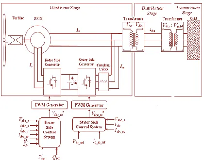
Both controlling of rotor- and stator-side converter voltagesend up with a current regulation part and a cross-couplingpart. The wind turbine driving DFIG wind power systemconsists of a wound-rotor induction generator and anac/dc/ac insulated gate bipolar transistor (IGBT)-based pulsewidth-modulated (PWM) converter (back-to-back converter with capacitor dc link), as shown in Fig. 3. In thisconfiguration, the back-to-back converter consists of twoparts: the stator-grid-side converter and the rotor-sideconverter. Both are voltage source converters using IGBTs,while a capacitor between two converters acts as a dcvoltage source. The generator stator windings are connecteddirectly to grid (with fixed voltage and frequency of grid)while the rotor winding is fed by rotor-side converterthrough slip rings and brushes, at variable frequency.
Fig. 3 Wind turbine–doubly fed Induction generator system configuration
The control system is divided into two parts stator-sideconverter control system and rotor-side converter controlsystem. An equivalent circuit of DFIG is depicted in Fig. 8,and the relation equations for voltage V , current I, flux Ψ,and torquebTe involve
[4], [5], [7] are
Vds =RsIds − ωsΨqs +dΨds/dt……..1
Vqs =RsIqs + ωsΨds +dΨqs/dt……..2
Vdr =RrIdr − sωsΨqr +dΨdr/dt……..3
Vqr =RrIqr + sωsΨdr +dΨqr/dt……..4
Ψds =LsIds + LmIdr………5
Ψqs =LsIqs + LmIqr…………...…….6
Ψdr =LrIdr + LmIds……….7
Ψqr =LrIqr + LmIqs ……….8
Te =3/2{np(ΨdsIqs − ΨqsIds)}...…….9
where Ls= Lls + Lm; Lr = Llr + Lm; sωs = ωs – ωr
representsthe difference between synchronous speed and rotor speed;subscripts r, s, d, and q denote the rotor, stator, d-axis, and qaxis components, respectively; Te is electromagnetic torque;and Lm, np,
and J are generator mutual inductance, thenumber of pole pairs, and the inertia coefficient,respectively.
Fig. 4.Equivalent circuit of DFIG. (a) d-axis model. (b) q-axis model.
Rotors-Side Converter Control
If the derivative parts in (5) are neglected, one can obtainstator flux as
Ψds=(Vqs − RsIqs)/ωs
Ψqs=(Vds − RsIds)/(−ωs)
Ψs =SQRT(Ψ2ds +Ψ2qs) ………….10
Because of being directly connected to the grid, the statorvoltage shares constant magnitude and frequency of the grid.One could make the d-axis align with stator voltage vector; itis true that Vs = Vds
stator-voltage-oriented vector control schemeas depicted in Fig. 5.
According to (7)–(9), the rotor-side converter referencecurrent is derived as
Idr_ref = − 2LsTe/3npLmΨs ………11
where
Pe_ref =Popt − Ploss= Teωr………..12
Ploss =RsI2s + RrI2r + RcI2sc + Fω2…….13
whereIsc, Rc, and F are stator-side converter current,
chokeresistance, and friction factor, respectively. Popt,
Pe_refandPloss are desired optimal output active
power, referenceactive power, and system power loss. Combining (10)–(12),the active power is used as command inputs to determinecurrent reference Idr_ref.
Meanwhile, the output reactive loads power is the stator reactive output power since the stator-sideconverter’s reactive power is set to be zero.
Fig. 5. Stator voltage FOC reference frame
Stator-Side Converter Control
Concerning the use of three-phase series RL choke betweenstator- and stator-side converter, a cross-coupling model isrequired to derive the voltage signal of stator-side converter,as described in Fig.6
Fig. 11. Equivalent circuit of stator-side-converter choke. (a) d-axis model.(b) q-axis model.
Vdsc =Vds – Vdch …………..14
Vqsc =Vqs – Vqch …………..15
where the subscripts sc and ch denote the variables of statorside converter and choke. The coupling part of voltagesignals V 2 dch and V 2qch is expressed as V2
dch =RcIdsc – ωsLcIqsc …………..16
V2
qch =RcIqsc + ωsLcIdsc . …………. (17)
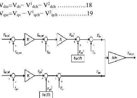
Moreover, V 1dch and V 1qch are determined by the regulation of currents Idsc and Iqsc in which the currentreference Iqsc_ref is given directly while Idsc_ref isdetermined by the regulation of dc-link voltage Vdc. Thus,above all, the stator-side converter voltage signals Vdsc andVqsc are obtained as follows and depicted in Fig. 7
Vdsc=Vds− V1dch− V2dch …………..18
Vqsc=Vqs − V1qch− V2qch …………..19
Fig. 7. Stator-side converter control scheme
III. SIMULATION AND RESULTS
the optimal (maximum)output power operation in the absence of reactive powersource. Also, the independent control of active and reactivepower is achieved. In the Matlab / Simulink model, theconverter switch frequency is set to be 27 times the gridfrequency f.A traditional SCIG wind power system is developed in Matlab/Simulink, and the related system dataused are given in Table II. In order to investigate the system performances, a ramp wind speed vw is assumedthat varies from t=10stot=16s and, then, it remains constant to the end of simulation t=40s. Fig. 8(a)–(e) showsthe dynamic variations and steady states of pitch angle β, generator speed ωr, produced active power P, andconsumed reactive power Q. First, he fluctuation in the results during t=0to 2.5 s is due to the initial conditions.In the simulation, the initial speed of generator is set at slip s=−0.01p.u. with respect to synchronous speed and,then, response to the wind speed input disturbance. Other initial values for power and voltages are zero. Since itis lower than nominal value of 0.855 MW, pitch angle control is not working. After t=10s, with the increase ofvw, so do the ωr and P until t=13s when vw exceeds the nominal value (11 m/s)
Fig.8 Dynamic responses to grid voltage droop. (a) DC-link voltage Vdc. (b) Rotor speedωr. (c) Active
powerP. (d) Reactive power Q. (e) Grid voltage Vgrid.
IV. CONCLUSION
maximum wind power capture at different windspeeds.
REFERENCES
[1] M. Orabi, T. Ahmed, and M. Nakaoka, “Efficient performances of induction generator for wind energy utilization,” in Proc. 30th Annu. Conf.IEEE Ind. Elect. Soc., Nov. 2004, pp. 838–843.
[2] M. Molinas, J. A. Suul, and T. Undeland, “Low voltage ride through ofwind farms with cage generators: STATCOM versus SVC,” IEEE Trans.Power Electron., vol. 23, no. 3, pp. 1104–1117, May 2008.
[3] Z. Chen, J. M. Guerrero, and F. Blaabjerg, “A review of the state of theart of power electronics for wind turbines,” IEEE Trans. Power Electron.,vol. 24, no. 8, pp. 1859–1875, Aug. 2009.
[4] Y. Lei, A. Mullane, and G. Lightbody, “Modeling of the wind turbine witha doubly fed induction generator for grid integration studies,” IEEE Trans.Energy Convers., vol. 21, no. 1, pp. 257–264, Mar. 2006.
[5] R. Ganon, G. Sybille, and S. Bernard, “Modeling and real-time simulation of a doubly-fed induction generator driven by a wind turbine,” presented at the Int. Conf. Power Systems Transients, Montreal, QC, Canada,Jun. 2005, Paper IPST05-162.
[6] H. Sun, Y. Ren, and H. Li, “DFIG wind power generation based on backto-back PWM converter,” in Proc. IEEE Int. Conf. Mechatron. Autom.,Aug. 2009, pp. 2276–2280.
[7] L. Xu and P. Cartwright, “Direct active and reactive power control ofDFIG for wind energy generation,” IEEE Trans. Energy Convers., vol. 21,no. 3, pp. 750–758, Sep. 2006.
[8] S. Heier, Grid Integration of Wind Energy Conversion Systems.Hoboken, NJ, USA: Wiley, 2006.
[9] N. W. Miller, W. W. Price, and J. J. Sanchez-Gasca, “Dynamic modelingof GE 1.5 And 3.6 wind
turbine-generators,” GE Power Systems EnergyConsulting, Gen. Elect. Int., Inc., Schenectady, NY, USA, Oct. 2003.
[10] R. Pena, J. C. Clare, and G. M. Asher, “Doubly fed induction generatorusing back-to-back PWM converters and its application to variable-speedwind-energy generation,” Proc. Inst. Elect. Eng.—Elect. Power Appl.,vol. 143, no. 3, pp. 231–241, May 1996.
[11] Feijoo, J. Cidras, and C. Carrillo, “Third order model for the doubly-fedinduction machine,” Elect. Power Syst. Res., vol. 56, no. 2, pp. 121–127,Nov. 2000.