Available online: https://edupediapublications.org/journals/index.php/IJR/ P a g e | 206
Implementation of MMIC-Based Link for Data Transmission of
Complex Modulated Signals in the E-Band
ABSTRACT
This paper presents the wireless data transmission of complex modulated signals in the E-band using a MMIC-based link compared to the current state of the art in millimeter-wave wireless communication. Highly linear and extremely broadband frontend compone nts in combination with the latest equipment to generate and analyze broadband complex data signals areused in this experiment. The received signal quality is evaluated in terms of EVM and BER. An error free QPSK transmission with a data rate of 40 Gbit/s over a wireless distance of 6m is presented, while the transmission of 80 Gbit/s signals, achieved by 16-QAM modulation, results in a BER of 3.7 × 10⁻³.
Index Terms—Millimeter-wave communication, wireless communication, data transmission, E-band, millimeter-wave monolithic integrated circuit (MMIC), radio link, complex modulated data signals
INTRODUCTION
Driven by the expanding number and reach out of up and coming applications in our worldwide and interconnected world, similar
to interpersonal organizations, distributed
computing or superior quality
video-ondemand, the requirement for both, wireline and remote information rates to meet the client's necessities, rises ceaselessly. Fiber optical arrangements are intended for todays wireline applications giving information rates up to a few Tbit/s. To accomplish high information rates for remote connections, both the transfer speed and unearthly effectiveness should be expanded. Since multi-gigabit information rates require multi-GHz transfer
speed, increasingly gatherings are working in the alleged millimeter wave (mmW) (30 to 300 GHz) or even sub-millimeter wave district (past 300 GHz).
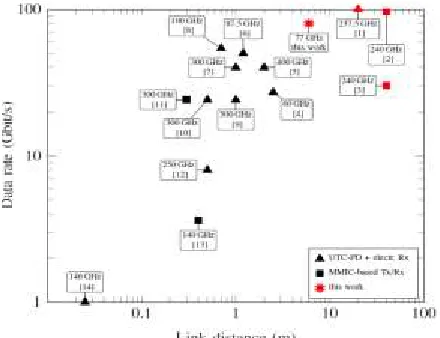
Fig. 1 speaks to the cutting edge for mmW remote correspondence joins, where every image speaks to a production, organized by
the accomplished information rate and
transmission separate. The vast majority of the gatherings create motions in the optical area and change over them to mmW recurrence by heterodyning on a uni-traveling-carrier (UTC) photodiode. Those gatherings utilize either Schottky-hindrance diodes at the beneficiary or monolithic integrated circuit (MMIC) based arrangements. Different gatherings are going
G. Vani M.Tech.,
Department of Electronics &
Communication Engineering, Vaagdevi College of Engineering,
J.N.T.University, Hyderabad, Telangana,
India, Email. Id. [email protected]
U. Kiran Asst.prof,
Department of Electronics & Communication Engineering,,
Vaagdevi College of Engineering, J.N.T.University,
Hyderabad, Telangana, India Email.Id.
U. VENU Asst.prof,
Department of Electronics Communication Engineering,
Vaagdevi College of Engineering, J.N.T. University, Hyderabad,
Available online: https://edupediapublications.org/journals/index.php/IJR/ P a g e | 207
for a general electrical MMIC-based
arrangement, which looked at, to the optical
transmitter diminishes the frameworks
multifaceted nature. This paper exhibits a MMIC-based remote information transmission analyze in the alleged E-band, indicating the two recurrence groups between 71-76 GHz and 81-86 GHz designated for settled remote connections. Exceptionally direct and to a great degree broadband frontend parts in blend with the most recent Keysight hardware to create and dissect broadband complex information signals prompt to information rates up to 80 Gbit/s over a remote separation of 6 m.
Fig 1: State of the art in mmW wireless communication links. Experimentswhere the mmW signal is generated in the optical domain (UTC-PD) areindicated by triangles. MMIC based measurements are indicated by squares,and the red star denotes the result of this work.
RF-FRONTEND COMPONENTS
Organize change inphase/quadrature (I/Q) up-and downconverter MMICs, packaged into split-square waveguide modules were used to comprehend the fronted portions for the remote association. The recipient, made out of a resistive blender and a low-confusion
intensifier (LNA), was made in a 50 nm alterable metamorphic highelectron mobility transistor (mHEMT) development for low clatter operation. A 18 GHz, 3 dB intermediatefrequency (IF) exchange speed was measured. On the transmitter side, a balanced blender was delineated in a 100 nm mHEMT development to get a high linearity, high return control with a 3 dB IF information exchange limit of 12 GHz and 36 dB local oscillator (LO) to radio repeat (RF) separation. Repeat multipliers by eight are used to make the LO for both, the up-and downconverter. The RF-frontend sections used for this investigation are depicted in more detail in [15].
MEASUREMENT SETUP
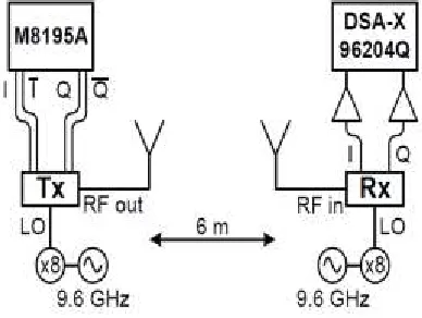
Fig. 2 demonstrates a schematic of the E-band remote connection. Two 9.6 GHz signals, out of free running and non-synchronizedKeysight MXG N5183B synthesizers drive the MMIC-based recurrence multipliers to create the 77 GHz LO signals. For appropriate connection arrangement, the RF-frontend parts, are mounted together with appended horn radio wires onto customizable tripods, isolated by a free space separation of 6 m. Every horn recieving wire gives a radio wire pick up GTx,Rx of 23 dBi. While applying the information motion at the transmitter's info, −5 dBm yield power was measured. To figure the connection moved for this short range test, the atmospherical constriction in the request of 0.5 dB/km can be dismissed [16]. Taking just the free space way misfortune (FSPL) of 85.74 dB at the flag's inside recurrence of 77 GHz for the 6m remote separation into record, the got flag influence can be ascertained after:
PRx = PTx +GA,Tx − FSPL + GA,Rx (1) = −5 dBm + 23 dBi − 85.74 dB + 23 dBi
Available online: https://edupediapublications.org/journals/index.php/IJR/ P a g e | 208
Due to the enormous bandwidth of the
RF-frontend components,up to now the
transmission experiments were limitedin
bandwidth by the measurement equipment, especially bythe data signal source. For this experiment a Keysight arbitrarywave form
generator (AWG) M8195A with a
maximumsample rate of 65 GSa/s, 20 GHz analog bandwidth and 8 bitvertical resolution
was used as signal source. The
AWG’sdifferential output channels are
directly connected to thetransmitter module and set to the maximum output amplitudeof 2Vpp. Compared to the transmitter and receiver module,with 18 and 12 GHz of bandwidth, the AWG does not limitthe bandwidth for these measurements.At the receiver’s output, the I- and Q-signals are
postamplifiedby broadband and
phase-matched 22 dB amplifiersand captured by a
Keysight DSA-X 96204Q Infiniium
highperformancereal-time oscilloscope with
160 GSa/s samplerate, an analog bandwidth of 63 GHz and 8 bit vertical resolution.The high accuracy in time and amplitude combined withthe huge memory depth of 2 Gpts allows a detailed analysisof the received signal quality.To provide accurate phase relations for the baseband data,phase-matched RF cables with a phase difference below 0.25_at 20 GHz are used in the whole setup.
SIGNAL GENERATION AND ANALYSIS To generate the complex I/Q-data signals for this experiment, an order 15 pseudorandom binary sequence (PRBS15) was generated in MATLAB. This bitstream is used as datasource. In the next step, the bits are mapped to complex symbols by taking two bits per symbol for quadrature phaseshift keying (QPSK) modulation, three bits for 8-PSK and8-quadrature amplitude modulation (8-QAM), and four bits per symbol for 16-QAM. Repeating each symbol three timesand operating the Keysight M8195A AWG at 60
GSa/s leadsto a symbol rate of 20 GBd and due to the different spectralefficiencies to data rates of 40 Gbit/s (QPSK), 60 Gbit/s(8-PSK and 8-QAM) and 80 Gbit/s (16-QAM), respectively.
Fig 2. Measurement setup for the 6m incoherent wireless transmission.
The I and Q-part of those mind boggling signs are advanced to-simple changed over by two channels out of the AWG and specifically nourished to the transmitter module. On the
recipient side, simple to-advanced
transformation is finished by the DSA-X 96204Q oscilloscope, catching the signs in recordings with a length of 500 μs. Because of the free running synthesizers and since there is no equipment bearer recuperation executed in this setup, the two LO signals don't work at the very same recurrence and the stage distinction is changing after some time. Utilizing Keysight's vector signal analyzer (VSA) programming, the got signal is subdivided in 2000 bundles, each containing 4096 images and dissected in computerized
disconnected preparing. The VSA
programming plays out the bearer
Available online: https://edupediapublications.org/journals/index.php/IJR/ P a g e | 209
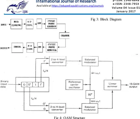
Fig 3: Block Diagram
Fig 4: QAM Structure
The got signal is explored as far as blunder vector size (EVM), which serves as measure for the broke down signal quality. To decide the genuine execution of the information transmission additionally the bit blunder
proportion (BER) is assessed. The
demodulated bitstream is exchanged to MATLAB. The group of stars outline spoke to by the VSA programming can be mapped in various courses because of inevitable turns
and reflecting created by the ambiguous LO signals. Along these lines, the crosscorrelation between the first signal in every conceivable mapping and the got signal is performed to decide the mapping and position in time. Contrasting the transmitted piece succession and the got signal, the BER is ascertained by the proportion between the quantity of mistaken bits and the aggregate number of looked at bits:
.
.
No oferroneousbits
Available online: https://edupediapublications.org/journals/index.php/IJR/ P a g e | 210
MEASUREMENT RESULTS
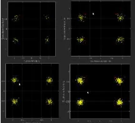
Fig 5:. BER Analysis
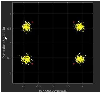
The constellation diagrams together with the corresponding EVM and BER values of the
received 20 GBd signals after a wireless transmission distance of 6m are shown in Fig. 6(a) and 6(b).
Available online: https://edupediapublications.org/journals/index.php/IJR/ P a g e | 211
Fig. 6(b): Constellation diagrams of the received 20 GBd signals transmitted over a wireless distance of 6 m.
CONCLUSION
We effectively exhibited MMIC-based
information transmission at 77 GHz focus recurrence with record information rates up to 80 Gbit/s. The broadband information signal was produced utilizing a Keysight M8195A
AWG specifically associated with the
transmitter module. After 6m remote
transmission, the complex baseband signal was caught by a Keysight DSA-X 96204Q ongoing oscilloscope and broke down as far as EVM and BER. To the best of our insight and as demonstrated by a best in class examination, this paper exhibits the most elevated information rate accomplished in E-band remote information transmission. A mistake free QPSK transmission with an
information rate of 40 Gbit/s is displayed, while the 80 Gbit/s transmission of 64-QAM
adjusted signs brings about a BER of
2.7x10⁻³.
REFERENCES
[1] S. Koenig, D. Lopez-Diaz, J. Antes, F. Boes, R. Henneberger,A. Leuther, A. Tessmann, R. Schmogrow, D. Hillerkuss, R. Palmer,T. Zwick, C. Koos, W. Freude, O. Ambacher, J. Leuthold, andI. Kallfass, “Wireless sub-thz communication system with high datarate,” Nat Photon, vol. 7, no.
12, pp. 977–981, Dec. 2013.
[Online].Available:
Available online: https://edupediapublications.org/journals/index.php/IJR/ P a g e | 212
[2] F. Boes, T. Messinger, J. Antes, D. Meier, A. Tessmann, A. Inam,
and I. Kallfass, “Ultra-broadband mmic-based wireless link at 240 ghzenabled by 64gs/s dac,” in Infrared, Millimeter, and
Terahertz waves(IRMMW-THz), 2014
39th International Conference on, Sept 2014, pp.1–2.
[3] J. Antes, S. Koenig, D. Lopez-Diaz, F. Boes, A. Tessmann, R. Henneberger,O. Ambacher, T. Zwick, and I. Kallfass, “Transmission ofan 8-psk modulated 30 gbit/s signal using an mmic-based 240
ghzwireless link,” in Microwave
Symposium Digest (IMS), 2013 IEEE MTTSInternational, June 2013, pp. 1–3. [4] M. Weiss, A. Sthr, F. Lecoche, and B.
Charbonnier, “27 gbit/s photonicwireless 60 ghz transmission system using 16-qam ofdm,” in MicrowavePhotonics, 2009. MWP ’09. International Topical Meeting on, Oct 2009,pp. 1–3.
[5] G. Ducournau, P. Szriftgiser, A. Beck, D. Bacquet, F. Pavanello, E. Peytavit,M. Zaknoune, T. Akalin, and J.-F. Lampin,
“Ultrawide-bandwidthsingle-channel
0.4-thz wireless link combining broadband
quasi-opticphotomixer and coherent
detection,” Terahertz Science and
Technology,IEEE Transactions on, vol. 4, no. 3, pp. 328–337, May 2014.
[6] X. Pang, A. Caballero, A. Dogadaev, V. Arlunno, R. Borkowski, J. S.Pedersen, L. Deng, F. Karinou, F. Roubeau, D. Zibar, X. Yu, and I. T.Monroy, “100 gbit/s hybrid optical fiber-wireless link in the w-band (75-110 ghz),” Opt. Express, vol. 19, no. 25, pp. 24 944–24 949, Dec
2011.[Online]. Available:
http://www.opticsexpress.org/abstract.cfm ?URI=oe-19-25-24944
[7] T. Nagatsuma, “Generating millimeter and
terahertz waves by photonicsfor
communications and sensing,” in
Microwave Symposium Digest(IMS),
2013 IEEE MTT-S International, June 2013, pp. 1–3.
[8] X. Li, J. Yu, J. Zhang, Z. Dong, F. Li, and
N. Chi, “A400g optical wireless
integration delivery system,” Opt. Express, vol. 21, no. 16, pp. 18 812–18 819, Aug 2013.
[Online].
Available:http://www.opticsexpress.org/ab stract.cfm?URI=oe-21-16-18812
[9] T. Nagatsuma, S. Horiguchi, Y.
Minamikata, Y. Yoshimizu, S. Hisatake,S. Kuwano, N. Yoshimoto, J. Terada, and H.
Takahashi, “Terahertz
wirelesscommunications based on
photonics technologies,” Opt. Express,vol. 21, no. 23736-23747, 2013.
[10] H.-J. Song, K. Ajito, Y. Muramoto, A. Wakatsuki, T. Nagatsuma, andN. Kukutsu, “24 gbit/s data transmission in 300 ghz band for futureterahertz communications,” Electronics Letters, vol. 48, no. 15, pp. 953–954, July 2012.
[11] H.-J. Song, J.-Y. Kim, K. Ajito, M. Yaita, and N. Kukutsu, “Fullyintegrated ask
receiver mmic for terahertz
communications at 300 ghz,”Terahertz
Science and Technology, IEEE
Transactions on, vol. 3, no. 4,pp. 445–452, July 2013.
[12] H.-J. Song, K. Ajito, A. Hirata, A. Wakatsuki, Y. Muramoto, T. Furuta,N. Kukutsu, T. Nagatsuma, and Y. Kado, “8 gbit/s wireless datatransmission at 250 ghz,” Electronics Letters, vol. 45, no. 22, pp. 1121–1122, October 2009.
[13] R. Fujimoto, M. Motoyoshi, K. Takano, and M. Fujishima, “A 120ghz / 140 ghz dual-channel ask receiver using standard 65 nm cmostechnology,” in Microwave
Conference (EuMC), 2011 41st
European,Oct 2011, pp. 1189–1192. [14] M. J. Fice, E. Rouvalis, F. van Dijk, A.
Accard, F. Lelarge, C. C.Renaud, G. Carpintero, and A. J. Seeds, “146-ghz
Available online: https://edupediapublications.org/journals/index.php/IJR/ P a g e | 213
wireless transmission system,” Opt.
Express,vol. 20, no. 2, pp. 1769–1774, Jan
2012. [Online].
Available:http://www.opticsexpress.org/ab stract.cfm?URI=oe-20-2-1769
[15] J. Antes, U. Lewark, A. Tessmann, S. Wagner, A. Leuther, T. Zwick,and I. Kallfass, “Mmic-based chipset for
multi-gigabit satellite linksin e-band,” in
Wireless Information Technology and
Systems (ICWITS),2012 IEEE
International Conference on, 2012, pp. 1– 4.
[16] ITU Recommendation, “Attenuation by atmospheric gases,” ITU-RP.676-8, 10 2009.
[17] F. Chang, K. Onohara, and T. Mizuochi, “Forward error correction for100 g
transport networks,” Communications