Implementation of SPI Driver to Interface
MCP 3202 ADC to Raspberry Pi Board
Thejesh p, Dr. T Vijayakumar
Department of ECE, SJB Institute of Technology, Bangalore, India
Professor, Department of ECE, SJB Institute of Technology, Bangalore, India
ABSTRACT: Analog to digital converters are mainly used in embedded devices to convert the analog data received by the sensors to digital data. Raspberry pi board is equipped with a Serial peripheral bus to communicate with the low level peripherals. Linux operating system supports implementing the drivers for low level peripherals on raspberry pi.MCP 3202 is a successive approximation 10 bit analog to digital converter, the main aim of this project is to implement a device driver for MCP 3202 ADC to interface it to Raspberry pi board through Serial Peripheral Interface.
I. INTRODUCTION
Analog to digital converters are mainly used in embedded devices to convert the analog data received by the sensors to digital data. Raspberry pi board is equipped with a Serial peripheral bus to communicate with the low level peripherals. Linux operating system supports implementing the drivers for low level peripherals on raspberry pi.MCP 3202 is a successive approximation 10bit analog to digital converter. This enables the Raspberry Pi to interpret analog voltages that are in turn typically emitted by analog-based sensors to reflect a measure of a physical characteristic such as acceleration, light intensity or temperature, the main aim of this project is to implement a device driver for MCP 3202 ADC to interface it to Raspberry pi board through Serial Peripheral Interface.
The communication protocols which are used to communicate between master and slave devices are Inter Integrated Circuit (I2C), Serial Peripheral Interface (SPI), Universal Asynchronous Receiver and Transmitter (UART), here in this project the protocol used is SPI. The Serial Peripheral Interface (SPI) is a communication bus that is used to interface one or more slave peripheral integrated circuits (ICs) to a single master SPI device; usually a microcontroller or microprocessor of some sort. Many SPI Peripheral ICs exist. They include, analog to digital converters (ADC), digital to analog converters (DAC), general purpose input/output (GPIO) expansion ICs, temperature sensing ICs, accelerometers and many more. In this regards the SPI bus is similar to the I2C bus, the SPI's main advantage over the I2C bus is that the SPI bus speeds can be very fast.
The SPI bus is a '3+n wire' bus. Where 'n' is the number of slave devices attached to the master SPI device, a total of 6 wires are required by the SPI bus and six corresponding pins required on the master SPI device to interface the 3 slave SPI devices to the master SPI controller.
There are so many anolog to digital converters are available with different number of channels to sense the physical parameters of environment and outputs the digital data. Here in this project the ADC used is MCP3202. The MCP3202 chip is an SPI based analog to digital converter (ADC), it has 8 analog input channels that can be configured for single ended and differential ADC conversions. The resolution of MCP3202 is of 10 bit and it can convert up to 200 kilo samples per second. This ADC will use SPI protocol for communication. This ADC peripheral will be interfaced to Raspberry pi board through serial peripheral interface by implanting a device driver.
A device driver is a computer program that operates or controls a particular type of device that is attached to a computer. A driver provides a software interface to hardware devices, enabling operating systems and other computer programs to access hardware functions, A driver typically communicates with the device through the computer bus or communications subsystem to which the hardware connects. Device drivers simplify programming by acting as translator between a hardware device and the applications or operating systems that use it
II. SYSTEM OVERVIEW A. Raspberry pi board
The version of the board using in this project is a Raspberry pi 2 Model B and revision 2, when compared to the previous versions it is 6 times faster. It includes with an upgraded version of BCM2836 processor which is an architecture dependent of ARM cortex-A7 quad core processor which operates at 900 MHz, this advanced board will have the RAM of 1Giga bytes. The raspberry pi board is as shown in figure 1.
Fig 1: Raspberry pi 2 Model B board
The mentioned pi board is available with the peripherals such as HDMI port to connect to the monitor, 3.5mm audio jack, USB 2.0 ports, Ethernet port, SD card port where the OS image is loaded onto and 40 general purpose input/output pins.
This board supports both SPI and I2C protocols, this pi board can be now used a CPU. Since there is no inbuilt ADC’s in the board have to connect the ADC’s externally so that any sensors can be interfaced with the board using the communication protocols.
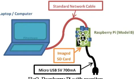
The connection of Raspberry pi board with the monitor is shown in figure 2.
Fig2. Raspberry Pi with monitor
B. Analog to digital converter MCP3202
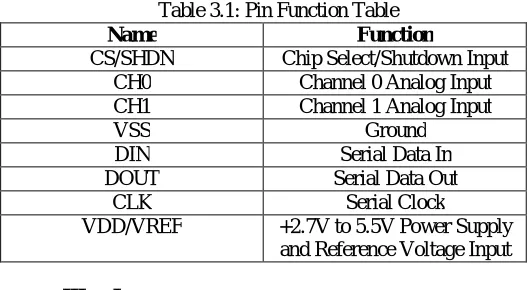
Fig 3: ADC MCP3202 The pin description of ADC MCP3202 is listed in the table 3.1.
Table 3.1: Pin Function Table
Name Function
CS/SHDN Chip Select/Shutdown Input CH0 Channel 0 Analog Input CH1 Channel 1 Analog Input
VSS Ground
DIN Serial Data In
DOUT Serial Data Out
CLK Serial Clock
VDD/VREF +2.7V to 5.5V Power Supply and Reference Voltage Input
III. LINUX OPERATING SYSTEM ARCHITECTURE
Linux is one of popular version of UNIX operating System. It is free to use. Linux was designed considering UNIX compatibility. The functionality list is quite similar to that of UNIX. Linux is a platform-independent software that is free, high quality, and embraced by the user community.
A. Features of Linux Operating System
Portable - Portability means software’s can works on different types of hardwares in same way. A Linux kernel and application program supports their installation on any kind of hardware platform.
Open Source - Linux source code is freely available and it is community based development project. Multiple teams’ works in collaboration to enhance the capability of Linux operating system and it is continuously evolving.
Multi-User - Linux is a multiuser system means multiple users can access system resources like memory/ ram/ application programs at same time.
Multiprogramming - Linux is a multiprogramming system means multiple applications can run at same time.
Hierarchical File System - Linux provides a standard file structure in which system files/ user files are arranged.
Shell - Linux provides a special interpreter program which can be used to execute commands of the operating system. It can be used to do various types of operations, call application programs etc.
B. Architecture of linux system
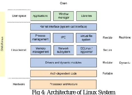
Fig 4: Architecture of Linux System
The architecture of the Linux system consists of three important sections namely User-space, kernel space and Hardware,
User Space is the space in memory where user processes run. This is available above the kernel and the user space is protected. The system prevents one process from interfering with another process. And only Kernel processes can access a user process. The user space covers all the applications in which the user needs and it contains all the libraries.
Kernel Space is the space in memory where all kernel services are provided via kernel processes. It is included with process management, memory management, network subsystems and drivers. The user has access to it only through the system call. A user process becomes a kernel process when it executes a system call.
Hardware part consists of the peripherals such as block devices, character devices and network devices, these devices will interact with the user application. In order to connect these peripherals have to write the drivers for particular hardwares.
IV. DEVICE DRIVERS AND SPI
A device driver is a computer program that operates or controls a particular type of device that is attached to a computer. A driver provides a software interface to hardware devices, enabling operating systems and other computer programs to access hardware functions, A driver typically communicates with the device through the computer bus or communications subsystem to which the hardware connects. The driver for MCP3008 is written to interface it into the Raspberry Pi board.
The main classification in Device Drivers is
Character Drivers: In character type drivers the communication between the hardware and operating system happens through the characters, example for such devices are mouse, keyboard etc.
Block Drivers: In block type of drivers the processing between the hardware and the operating system will done through the block of characters, example for such devices are pen drives, hard disks, printers etc.
Network Drivers: the communication between the hardware and operating system happens through the internet protocol system, example for such types is Ethernet.
The driver for particular type of devices is written to interact with the OS; in this proposed project the driver for analog to digital converter is written which is of the type character driver.
Since SPI is synchronous, it has a clock pulse along with the data. RS-232 and other asynchronous protocols do not use a clock pulse, but the data must be timed very accurately.
SPI is a Master-Slave protocol. Only the master device can control the clock line, SCK. No data will be transferred unless the clock is manipulated. All slaves are controlled by the clock which is manipulated by the master device. The slaves may not manipulate the clock. The connection between 3SPI Slave Devices to a Single SPI Master Device is shown in figure 5.
Fig5: 3SPI Slave Devices Connected to Single SPI Master Device.
SPI is a Data Exchange protocol. As data is being clocked out, new data is also being clocked in. When one “transmits” data, the incoming data must be read before attempting to transmit again. If the incoming data is not read, then the data will be lost and the SPI module may become disabled as a result. Always read the data after a transfer has taken place, even if the data has no use in the application. Data is always “exchanged” between devices. No device can just be a “transmitter” or just a “receiver” in SPI. However, each device has two data lines, one for input and one for output. These data exchanges are controlled by the clock line, SCK, which is controlled by the master device.
REFERENCES
[1] Matt Richardson and Shawn Wallace, “getting started with Raspberry Pi”, Ed. United States of America, 2012, PP. 1-42. [2] Simon Monk, “Programming the Raspberry Pi”, McGraw- Hill companies, 2013, PP. 15-75.
[3] Peter Membrey and David Hows, “Raspberry Pi with Linux”, 2012, PP. 1-149. [4] Alessandro Rubini, Jonathan Corbet, “Linux Device Drivers”, Oreilly, 1998, PP. 1-500. [5] Rushi Gajjan, “Raspberry Pi sensors”, Packt, 2015, PP. 38-39.
[6] David calcutt, Fraderick Crown, Hassan Parchizadeh, “8051 microcontroller: An application based introduction”, Jordon hill, 2004, PP. 129-150.
[7] ADC MCP3202 Datasheet, “Dual channel 10 bit analog to digital converter”, Microchip Technogies Inc, 2007, PP. 1-26.