ISSN (Print) : 2320 – 3765 ISSN (Online): 2278 – 8875
I
nternational
J
ournal of
A
dvanced
R
esearch in
E
lectrical,
E
lectronics and
I
nstrumentation
E
ngineering
(An ISO 3297: 2007 Certified Organization)
Website: www.ijareeie.com
Vol. 6, Issue 7, July 2017
Voltage Injection-Based Control Strategy for a
Parallel Hybrid Modular Multilevel HVDC
Converter System
T.Jagan Mohan Raju
Asst. Professor, Dept. of EEE, UCEKU, Kothagudem,Telanagana, India
ABSTRACT:This paper presents a Positive-Sequence Voltage Injection (PSVI) based model predictive control (MPC) strategy to control the dc current/power flow and simultaneously minimize the dc current ripple. For discrete-time dynamic model of the dc transmission-line current and, correspondingly, develops. Harmonics injection for proposed PSVI. Proposed strategy for a multilevel PHMMC-based HVDC station system is evaluated based on time-domain simulation studies. Regulating the dc current and power flow at their desired values. And also reducing/ eliminating dc current/voltage ripple of a PHMMC HVDC system, under various operating conditions.
KEYWORDS:Positive-Sequence Voltage Injection (PSVI), High Voltage Direct Current (HVDC), voltage source.
I. INTRODUCTION
High Voltage Direct Current (HVDC) is the electric power transmission choice utilized in large amount of power over long distances with minimal losses. Considering the fact that in a conventional three phase system the power delivered is conformed by its RMS value, HVDC allows transmitting active power with higher voltage range. Moreover, the impedance created in AC transmission systems are avoidable decreasing the power losses. Therefore, the initial installation cost of HVDC is higher than HVAC systems but due to lower losses it becomes cost effective over the time. For example, power delivered from remote offshore wind farms can be efficiently fed into power grids onshore via HVDC technology. Moreover, HVDC systems are useful to interconnect asynchronous AC grids reliably. Using HVDC system allows the possibility of using underground and susea cables. Hence, HVDC is considered as a highly efficient alternative for transmitting large amounts of electricity over long distances and for special purpose applications. As a key enabler in the future energy system based on renewables, HVDC is truly shaping the grid of the future.
1. New transformer less scalable modular multilevel converters for HVDC-transmission In this paper a novel concept of high voltage direct current converter (HVDC) is presented employing the modular multilevel converter (M2C). Converters using IGBT-power devices are getting increased importance in order to meet the global needs for reliable and environment friendly power supply and distribution. The problem addressed as results, a comparison of the semiconductor losses and the efficiencies of the different topologies are given.
ISSN (Print) : 2320 – 3765 ISSN (Online): 2278 – 8875
I
nternational
J
ournal of
A
dvanced
R
esearch in
E
lectrical,
E
lectronics and
I
nstrumentation
E
ngineering
(An ISO 3297: 2007 Certified Organization)
Website: www.ijareeie.com
Vol. 6, Issue 7, July 2017
Another MMC-HVDC installation named HVDC Light by ABB, is an adaptation of HVDC classic used to transmit electricity in power ranges (50-2500MW) transmitted using overhead lines and enviornmental friendly underground and sub-sea cables. It is used for grid interconnections and offshore links to wind farms. With HVDC Light, it is possible to transmit power in both directions and to support existing AC grids in order to increase robustness, stability, reliability and controllability. HVDC Light offers many other advantages and can be used in different applications which is explained in [5]. As outlined before, the main limitation of the two level converter is its high switching losses due to relatively high switching frequency which necessitates high insulation requirements of the transformer, as well as filters. The use of modular multilevel converters overcomes many of the aforementioned shortcomings, but at the expense of twice as many semi-conducting devices and a large distributed capacitor for each submodule. The principle idea of the hybrid VSC-HVDC, as used in HVDC MaxSine developed by Alstom, is to use a two level converter as the main switching component with low switching frequency and an MMC to provide a voltage wave shaping function on the AC side in order to eliminate the harmonics [6] [7].
2. Dynamic performance of a modular multilevel back-to-back HVDC system The modular multilevel converter (MMC) is a newly introduced switch-mode converter topology with the potential for high-voltage direct current (HVDC) transmission applications. This paper focuses on the dynamic performance of an MMC-based, back-to-back HVDC system.
Dynamic performance of the MMC-based back-to-back HVDC converter system, based on time-domain simulation studies in the PSCAD/EMTDC environment, is then evaluated.
3. Experimental validation of a parallel hybrid modular multilevel voltage source converter for HVDC transmission This paper discusses a small scale laboratory model constructed to validate the operation of a recently proposed parallel hybrid modular multilevel voltage source converter which is intended for HVDC applications. The problem addressed as presents a capacitor voltage balancing scheme for this converter and further demonstrates black start capability using a lower rated auxiliary DC source.
In the class of MMCs, the conventional series MMC has been extensively investigated [1], [3], [14]. Compared with the conventional series MMC, the hybrid MMCs can potentially reduce the ratings of the converter components and power losses. Particularly, due to fewer SMs operating outside the main power path, a PHMMC can potentially reduce the HVDC converter station losses if it is properly controlled [2], [4]–[8], [10], [11]. This paper is focused on the control aspects of a PHMMC-based HVDC station system.
II. PROPOSED SYSTEM
ISSN (Print) : 2320 – 3765 ISSN (Online): 2278 – 8875
I
nternational
J
ournal of
A
dvanced
R
esearch in
E
lectrical,
E
lectronics and
I
nstrumentation
E
ngineering
(An ISO 3297: 2007 Certified Organization)
Website: www.ijareeie.com
Vol. 6, Issue 7, July 2017
Fig.1 block diagram
The grid tie inverter (GTI) must synchronize its frequency with that of the grid (e.g. 50 or 60 Hz) using a local oscillator and limit the voltage to no higher than the grid voltage. HVDC is a technology which involves the transmission of electric power using direct current at high voltages. In recent times, the technology is mainly implemented using high power semiconductor devices for the AC/DC power conversion and vice versa. It offers an effective medium for transmitting large amounts of electric power over long distances. The technology of HVDC transmission also find applications.
Harmonics: Harmonic voltages and currents in an electric power system are a result of non-linear electric loads. Harmonic frequencies in the power grid are a frequent cause of power quality problems. Harmonics in power systems result in increased heating in the equipment and conductors, misfiring in variable speed drives, and torque pulsations in motors. Reduction of harmonics is considered desirable.
Current harmonics: Current harmonics are caused by non-linear loads. When a non-linear load, such as a rectifier, is connected to the system, it draws a current that is not necessarily sinusoidal. The current waveform can become quite complex, depending on the type of load and its interaction with other components of the system. Regardless of how complex the current waveform becomes, as described through Fourier series analysis, it is possible to decompose it into a series of simple sinusoids, which start at the power system fundamental frequency and occur at integer multiples of the fundamental frequency.
Voltage harmonics: Voltage harmonics are mostly caused by current harmonics. The voltage provided by the voltage
source will be distorted by current harmonics due to source impedance. If the source impedance of the voltage source is small, current harmonics will cause only small voltage harmonics.
III. SIMULATION AND RESULTS
For HVDC applications a high number (greater than 100) of series connected IGBTs are required to be connected in series to achieve the necessary voltage rating. This requires that the series string of IGBTs are hard switched introducing additional switching loss as well as extra complexity required to dynamically share the device voltage during the switching event. Definitions of fault scenarios in DC grids are established in this section. Faults are divided into dual pole faults involving two conductors and single pole faults restricted to one conductor in the system.
ISSN (Print) : 2320 – 3765 ISSN (Online): 2278 – 8875
I
nternational
J
ournal of
A
dvanced
R
esearch in
E
lectrical,
E
lectronics and
I
nstrumentation
E
ngineering
(An ISO 3297: 2007 Certified Organization)
Website: www.ijareeie.com
Vol. 6, Issue 7, July 2017
commutated power electronic semiconductor switches. Conventional PWM converters are used for wind turbines that have a permanent-magnet alternator. Today, insulated gate bipolar transistors are typical switching devices.
fig . 2 Simulation diagram
We plan to have the wind and geothermal generators transmit their AC power to a single HVDC converter station. The converter station would be sited to minimize the total distance of new AC lines needed to connect the generators to the switchyard where their incoming power would all be connected to the three-phase buses going into the converter station. The performance analysis is done using simulated results which are found using MATLAB.
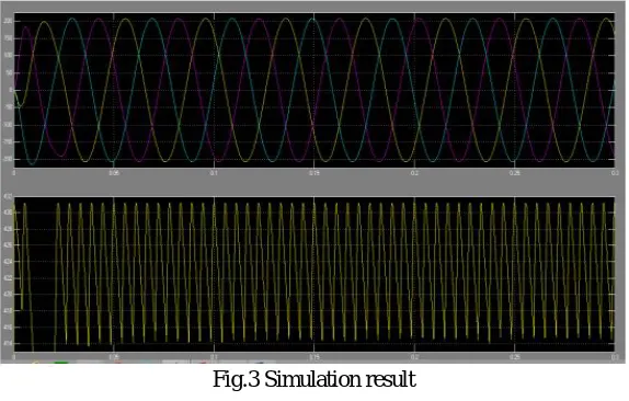
Fig.3 Simulation result
IV. CONCLUSION
ISSN (Print) : 2320 – 3765 ISSN (Online): 2278 – 8875
I
nternational
J
ournal of
A
dvanced
R
esearch in
E
lectrical,
E
lectronics and
I
nstrumentation
E
ngineering
(An ISO 3297: 2007 Certified Organization)
Website: www.ijareeie.com
Vol. 6, Issue 7, July 2017
REFERENCES
[1] S. Allebrod, R. Hamerski, and R. Marquardt, “New transformerless, scalable modular multilevel converters for HVDC-transmission,” in Proc. IEEE Power Electronics Specialists Conf., Jun. 2008, pp. 174–179.
[2] D. Trainer, C. Davidson, C. Oates, N. Macleod, D. Critchley, and R. Crookes, “A new hybrid voltage-sourced converter for HVDC power transmission,” in CIGRE Session, 2010.
[3] M. Saeedifard and R. Iravani, “Dynamic performance of a modular multilevel back-to-back HVDC system,” IEEE Trans. Power Del., vol. 25, no. 4, pp. 2903–2912, Oct. 2010.
[4] M. Merlin, T. Green, P. Mitcheson, D. Trainer, D. Critchley, and R. Crookes, “A new hybrid multi-level voltage-source converter with DC fault blocking capability,” in IET 9th International Conference on AC and DC Power Transmission, London, 2010.
[5] C. Davidson and D. Trainer, “Innovative concepts for hybrid multilevel converters for HVDC power transmission,” in Proc. 9th IET Int. Conf. AC DC Power Transm. ACDC. , 2010, pp. 1–5.
[6] R. Feldman, M. Tomasini, J. Clare, P. Wheeler, D. Trainer, and R. Whitehouse, “A hybrid voltage source converter arrangement for HVDC power transmission and reactive power compensation,” presented at the IET-PEMD, Brighton, U.K., Apr. 19–21, 2010.
[7] R. Feldman, M. Tomasini, J. Clare, P. Wheeler, D. Trainer, and R. Whitehouse, “A low loss modular multilevel voltage source converter for HVDC power transmission and reactive power compensation,” presented at the IET-ACDC, London, U.K., Oct. 20–21, 2010.
[8] M. Tomasini, R. Feldman, J. Clare, P. Wheeler, D. Trainer, and R. Whitehouse, “DC-link voltage ripple minimization in a modular multilevel voltage source converter for HVDC power transmission,” presented at the Eur. Conf. Power Electron. Appl., Birmingham, U.K., 2011.
[9] J. Qin and M. Saeedifard, “Predictive control of a modular multilevel converter for a back-to-back HVDC system,” IEEE Trans. Power Del., vol. 27, no. 3, pp. 1538–1547, Jul. 2012.
[10] E. Amankwah, A. Watson, R. Feldman, J. Clare, and P. Wheeler, “Experimental validation of a parallel hybrid modular multilevel voltage source converter for hvdc transmission,” in Proc. 28th Annu. IEEE Appl. Power Electron. Conf. Expo., 2013, pp. 1607–1614.
[11] R. Feldman, M. Tomasini, E. Amankwah, J. Clare, P. Wheeler, D. Trainer, and R. Whitehouse, “A hybrid modular multilevel voltage source converter for hvdc power transmission,” IEEE Trans. Ind. Appl., vol. 49, no. 4, pp. 1577–1588, Jul./Aug. 2013.
[12] S. Debnath, J. Qin, B. Bahrani, M. Saeedifard, and P. Barbosa, “Operation, control, applications of the modular multilevel converter: A review,” IEEE Trans. Power Electron., 2014, to be published.
[13] M. Perez, S. Bernet, J. Rodriguez, S. Kouro, and R. Lizana, “Circuit topologies, modelling, control schemes and applications of modular multilevel converters,” IEEE Trans. Power Electron., 2014, to be published.
[14] B. Gemmell, J. Dorn, D. Retzmann, and D. Soerangr, “Prospects of multilevel VSC technologies for power transmission,” in Proc. IEEE Transm. Distrib. Conf. Expo., Apr. 2008, pp. 1–16.